Chapter 14
Extensive Bone Grafts
Introduction
Extraoral bone graft donor sites include the Iliac crest, tibia, skull and rib.
Iliac Crest
The iliac crest provides ample cortical, cortico-cancellous and cancellous bone and has contours that are easy to manipulate for use in the jaws; it is, therefore, the donor site of choice. The lateral aspect of the anterior iliac crest offers the most suitable shape and reduces the risk of peritoneal perforation. It is preferred to the posterior iliac crest to avoid turning the patient over and it permits simultaneous donor and recipient site surgery. Bicortical grafts for the reconstruction of class V and VI jaws can be harvested. The use of ‘J’-shaped grafts offering two cortical surfaces is available for the management of class IV jaws. In addition, cancellous bone can also be obtained for the augmentation of the sinuses. The iliac crest is superficially placed, thus allowing easy access. The lateral femoral cutaneous nerve normally traverses anterior to the anterior iliac spine. However, in 10% of individuals, it traverses directly across the crest. Surgery must be carried out carefully to avoid damage to this nerve and subsequent paraesthesia of the skin over the lateral aspect of the thigh. Post-operative pain is associated with movement because of the disturbance of the abdominal and thigh muscles. Recovery is complete following a period ranging from one to four weeks. This does, however, depend on careful layered suturing of periosteum, muscle, adipose tissue, and skin. Otherwise, there are relatively few risks and the resulting scar can be easily concealed. Removal of bone from this site results in the least morbidity and risk.
Tibia
There is a limited amount of bone available from the tibia, even though access is excellent. As this is a stress-bearing bone, availability is limited and there is a risk of subsequent fracture through increases in stress in the harvest area. Patients may object to the potential visible scar.
Skull
The parietal bone offers monocortical grafts that are difficult to adapt to the recipient site and are of limited thickness. The density of the cortical bone increases the healing time for vascularisation to be completed. No cancellous bone is available and there are obvious concerns about the proximity of the brain. The presence of hair and the proximity to the oral cavity pose further operational difficulties.
Rib
Ribs comprise monocortical tubular bone with little or no cancellous bone, but because of its shape and composition, a graft is difficult to adapt. Risk of perforation of the pleural cavity and post-operative pain exclude the use of the rib in most cases.
Assessment
Assessment for extensive bone grafts involves observing the patient’s facial profile as an indicator of the extent of the atrophy of both the hard and soft tissues that has taken place. Examination of the intraoral soft tissues with the potential for covering the graft must also be assessed.
Assessment of the bone volume and its relationship to the ideal tooth position is fundamental to the outcome and planning. This is achieved by using radiopaque markers to identify tooth positions that can be related to the images obtained from the CT scan (Figs 14-1 and 14-2).
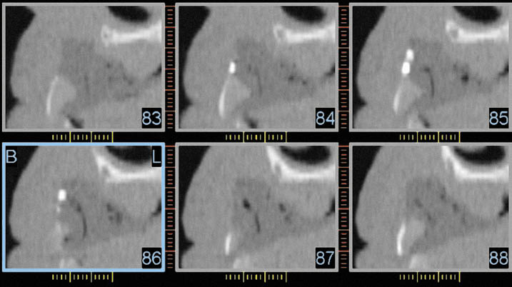
Fig 14-1 CT scan reconstruction of the anterior maxilla in the canine and lateral incisor region (Class VI). The radiopaque markers to identify the tooth position (cross section 85/lateral incisor with two markers, buccal side on the left-hand side) can be seen. The outline of the future tooth position can also be identified to relate it to the residual bone for purposes of planning the harvesting and positioning of the graft.
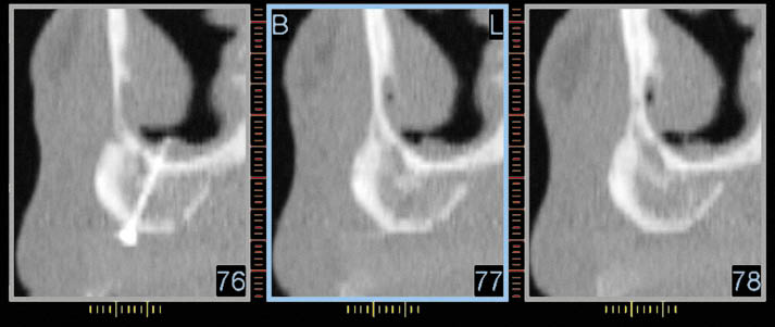
Fig 14-2 CT scan reconstruction of the anterior maxilla in the canine region showing the reconstructed alveolar ridge prior to implant placement. The fixation screw is visible. The radiopaque marker identifying future tooth position is only just visible at the bottom of each image. The CT scan provides essential information for the planning of implant placement.
Classification
Classification of the degree of atrophy is useful for deciding which corrective procedures should be implemented, and there are several accepted systems available for this purpose. We use the classification of Cawood and Howell (see Chapter 6)50 as a guideline for the clinical management of atrophied jaws:
- 1. Class IV: loss of width, which includes ridges with loss of height of up to 5 mm (Figs 14-3 and 14-4)
- 2. Class V: loss of entire or substantial part of the alveolar process (Figs 14-5 and 14-6)
- 3. Class VI: loss of entire alveolar process as well as erosion of the basal bone (Figs 14-7 and 14-8).
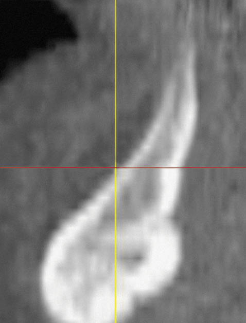
Fig 14-3 CT cross-section of a class IV mandible.
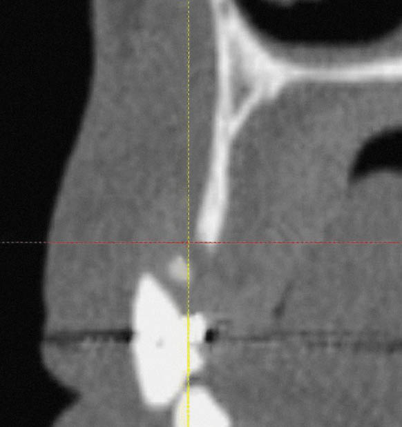
Fig 14-4 CT cross-section of a class IV maxilla, with fused cortical plates.
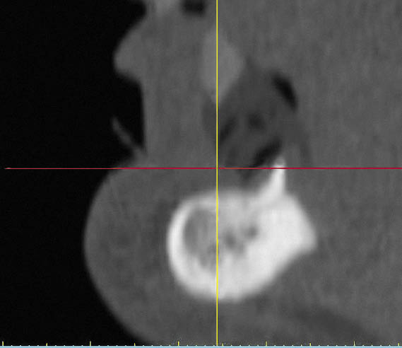
Fig 14-5 CT cross-section of a class V mandible.
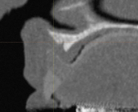
Fig 14-6 CT cross-section of a class V maxilla.
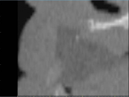
Fig 14-7 CT cross-section of a class VI maxilla.
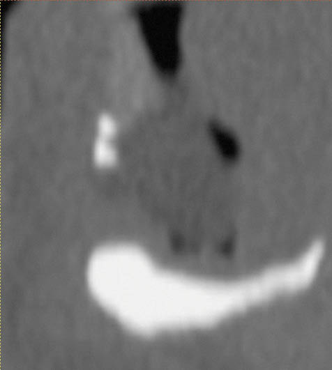
Fig 14-8 CT cross-section of a class VI mandible.
Loss of Width (Class IV)
Ridges that are not suitable for expansion (with fused cortical plates) but are of an acceptable height will require a bone graft for the purpose of increasing the width as well as offering circumoral soft tissue support.
Loss of Width and Height (Class IV)
Narrow ridges that require an increase in width and up to 5 mm in height may be placed within this category. The decision is based on bone volume and on the relationship of the desired tooth position to the ridge. Aesthetic considerations often play a fundamental role in the decision-making process.
Substantial Loss of Height: The Entire Alveolar Process (Class V)
A substantial loss of height is linked with a loss of facial form and function. The reconstruction of the entire alveolar ridge requires treatment planning directed at the positioning of the bone graft, relating it to the tooth position, correcting the facial form and bringing the patient into function.
Substantial Loss of Height: The Entire Alveolar Process and Basal Bone (Class VI)
In addition to the challenges of managing a Class V jaw, additional difficulties relating to availability of sufficient bone, graft fixation and soft tissue coverage of the graft make this class challenging to manage. Invariably, supplemental soft tissue surgery is required. The definitive restoration often has increased prosthetic tooth length.
Planning of Treatment
The diagnostic phase involves positioning teeth on a wax baseplate in a position that provides the required support for the circumoral soft tissues to achieve the correct facial profile. The size, shape and position of the teeth have to meet the patient’s aesthetic needs and expectations and eventually have to enable the patient to function. Some assessment of the patient’s function may be carried out at this stage by using speech as an indicator of habitual muscular activity. Once the above criteria have been met, the teeth are painted with a radiopaque varnish to enable their position to be transferred to the CT images.
To obtain information about the quantity of bone that will need to be harvested, the selected tooth position is related to a stone cast of the edentulous ridge by means of a plaster matrix, and the wax of the try-in is eliminated. The space thus created between the teeth, set in the plaster matrix and the edentulous ridge, gives an indication of the amount of bone necessary to reconstruct the ridge. Silicone can be used to form a template that the orthopaedic or maxillofacial surgeon may use in determining the shape and size of the graft that is required.
Surgery
The surgical approach to treatment of the bone deficiencies outlined above depends on the extent and location of the atrophy.
Loss of Width and Height
Loss of width and minimal loss of height requiring reconstruction on the labial aspect of the ridge (up to 5 mm) can be treated by using an incision made in the palate creating a buccally based flap (Figs 14-9–14-11). Bone deficiencies on the palatal aspects of the ridge require the incision to be made on the labial aspect.
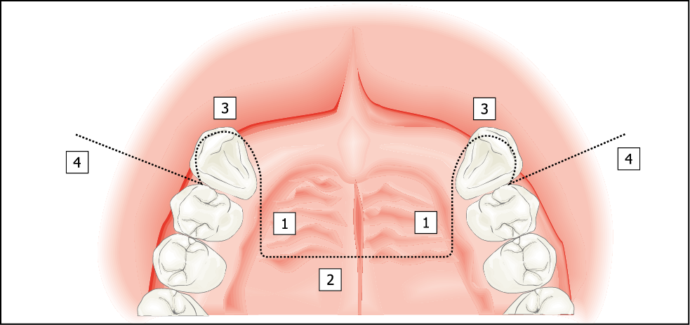
Fig 14-9 A palatal incision for more extensive bone graft requiring an increase in width on the labial aspect of the ridge and an increase in height of < 5 mm (Class IV).
1. Component extending into the palate by approximately 10 mm is made almost perpendicular to the ridge.
2. Bevelled component connecting the two incisions made with a Blake’s knife.
3. Intrasulcular cervical incision.
4. Vertical release incision including the papilla.
Fig 14-10 Cross-sectional view of the anterior maxilla depicting a remote palatal incision suitable for an increase in width and an increase in height of up to 5 mm on the labial aspect of the ridge. The extent of periosteal reflection is also shown. The periosteal reflection is extended to the anterior nasal spine, the piriform rim and the zygomatic process to enable the soft tissues to be closed over the graft.
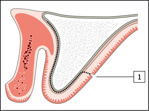
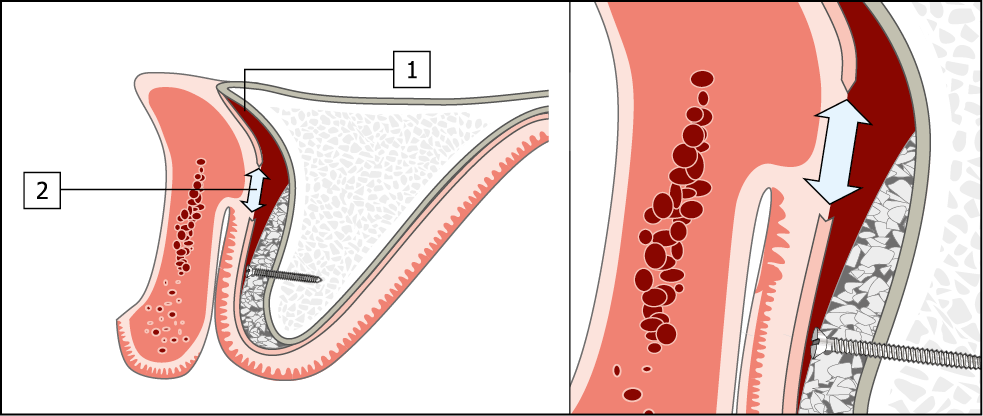
Fig 14-11 Creation of tissue for passive closure over a bone graft.
1. By reflection of the periosteum allowing tissue to be advanced.
2. By periosteal release incision. A reduction in the vestibular sulcus depth will result, with the labial tissue being advanced towards the palate.
Substantial Loss of Height
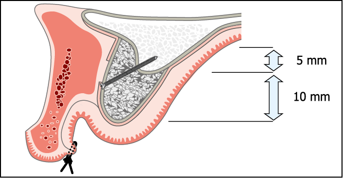
A labial incision made close to the vermilion border of the lip producing a palatally based flap is used whenever a substantial increase in ridge height is required (up to 15 mm) (Figs 14-12–14-14).
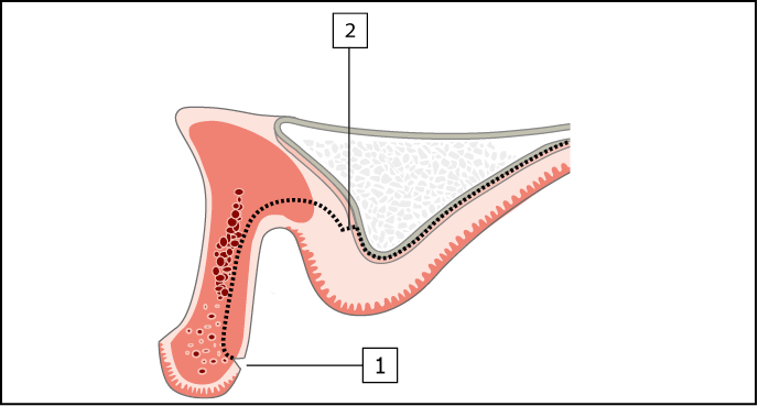
Fig 14-12 Cross-section of maxilla requiring augmentation in height (Class V and VI). A remote labial incision for an onlay graft requiring an increase in height of more than 5 mm on the crest and labial (most common) or palatal aspect of the ridge.
1. Split-thickness labial incision.
2. Periosteal incision and reflection of a full-thickness flap to expose crest of ridge.
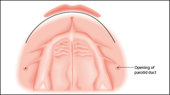
Fig 14-13 The remote labial incision (occlusal view) that will produce a palatally based flap. Care needs to be taken to avoid the opening of the parotid duct (parotid papilla).
Fig 14-14 Closure of the soft tissues over a large onlay bone graft. The wound is closed using mattress sutures, with a substantial reduction in sulcus depth.
Extensive Bone Grafts: Clinical Cases
Case 1: Bone Graft from the Iliac Crest for Reconstruction of a Deficient Ridge
This case study demonstrates the use of bone grafts obtained from an extraoral site for the reconstruction of a ridge destroyed by extensive periodontal disease. The treatment of this patient was driven prosthetically. A provisional metal-acrylic Rochette bridge was used to establish the correct tooth form. The information gathered was then transferred to the definitive restoration in a number of stages (described in Chapter 10). The provisional restoration was used to diagnose and identify the need for a bone graft in conjunction with diagnostic imaging consisting of CT scans and conventional radiographs. This case study is also described in Chapter 8, on provisional restorations (Figs 8-37–8-41, pp. 115–116). Harvesting bone from the iliac crest requires a general anaesthetic. Assessment of the patient in terms of general health is essential and must be carried out thoroughly to ensure the patient’s well-being. This is particularly necessary in view of the fact that surgery for the reconstruction of the jaws is an elective procedure. Preoperative assessment of the patient must also be carried out by the anaesthetist. Medical evaluation for this patient was carried out by Dr Michael Boscoe and included a physical examination, a blood test involving biochemistry and electrocardiography (Figs 14-15–14-42).
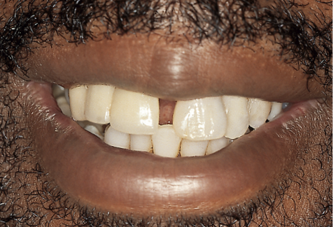
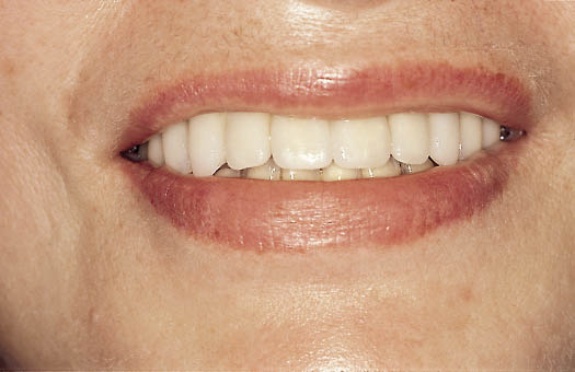
Fig 14-15 Preoperative view of the patient smiling, showing the displacement of the anterior teeth caused by advanced periodontal disease.
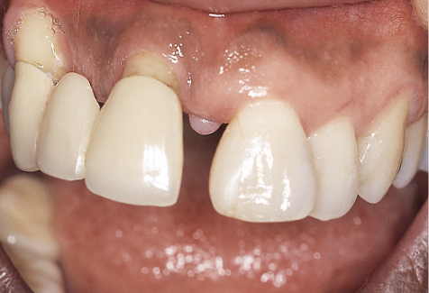
Fig 14-16 Labial view of the intraoral situation showing the central diastema and the exposure of the roots.
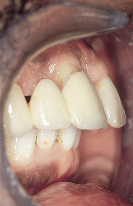
Fig 14-17 Lateral view of the failing dentition showing the degree of proclination that had taken place as a result of drifting caused by periodontal bone loss.
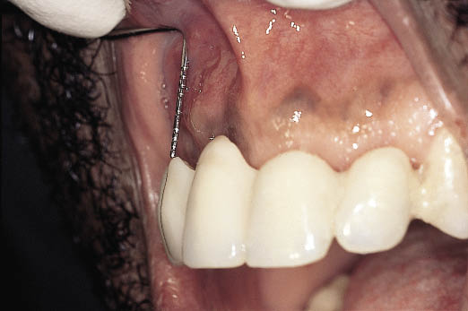
Fig 14-18 Lateral view of the provisional metal-acrylic Rochette bridge showing the loss of tissue on completion of soft tissue healing following tooth loss, in relation to the ideal tooth position.
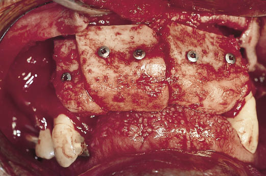
Fig 14-19 Cortico-cancellous bone grafts harvested from the iliac crest by the consultant orthopaedic surgeon (Mr Harbhajan). The cortical cancellous grafts were shaped and fitted to the residual ridge by means of screws. The position
and shape of the bone graft was determined and verified by
the provisional restoration and the diagnostic template.
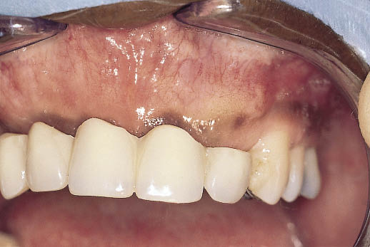
Fig 14-20 Post-operative view on the completion of healing prior to implant placement. The ridge has been reconstructed and can be seen in relationship to the provisional restoration, which has been modified to allow for the altered ridge dimensions. The bone graft was allowed to mature for a period of 10 weeks prior to implant placement.
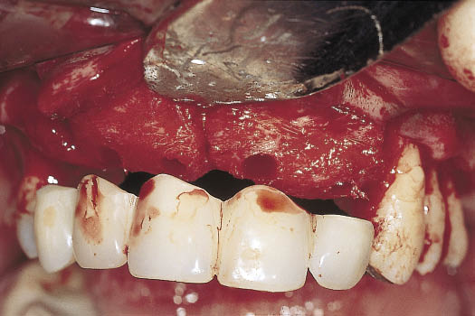
Fig 14-21 Intraoral operative view of the healed graft with the provisional restoration being used to select the implant positions.
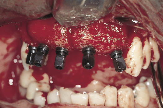
Fig 14-22 Labial view of the implants inserted with the implant carriers visible. Note the position and angulation of the implants. The implants have been placed so that they engage both the bone graft and the residual ridge. The point of emergence of the implants is coincident with the tooth position.
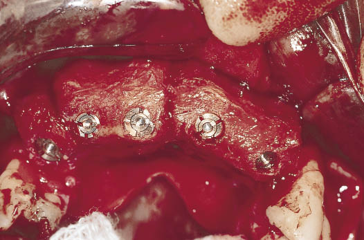
Fig 14-23 The clinical view of the implants with the carriers removed. The implants and the cover screws (which come pre-attached) can be seen.
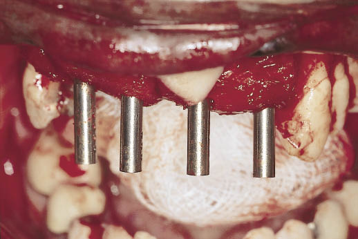
Fig 14-24 Prototype direction indicators can be seen being used to select the abutment to provide the correct alignment in readiness for the exposure of the implants on completion of integration.
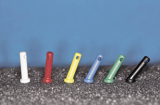
Fig 14-25 The range of six direction indicators with corresponding angles, which are colour coded for ease of identification.
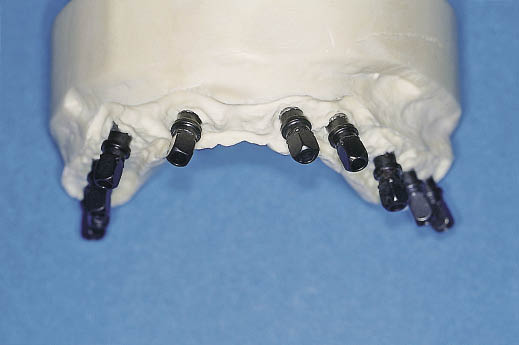
Fig 14-26 Laboratory cast with the implant carriers attached to the implant analogues to demonstrate the range of angles at which the implants have been placed in an edentulous maxilla.
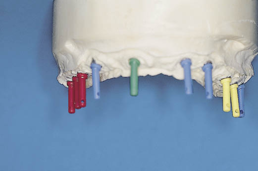
Fig 14-27 The laboratory cast demonstrates the use of direction indicators to select abutments. Direction indicators are used to choose the angled abutment, which will fit within the prosthetic envelope and provide parallel and aligned abutments for the prosthetic phase. The direction indicators fit into the cover screw. Note the range of angles that have been used, ranging from 7.5 degrees (yellow) to 30 degrees (green).
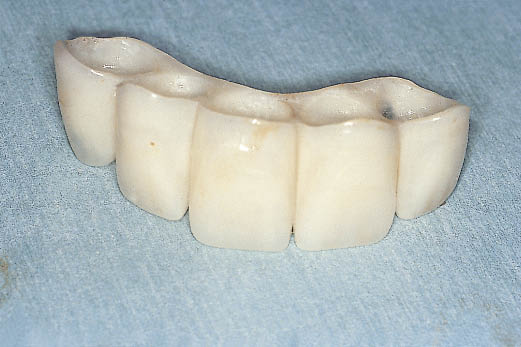
Fig 14-28 Hollow acrylic resin transitional restoration fabricated from information gained from the provisional metal-acrylic Rochette bridge. The transitional restoration is designed to fit over the abutments, which were selected using the diagnostic template and direction indicators.
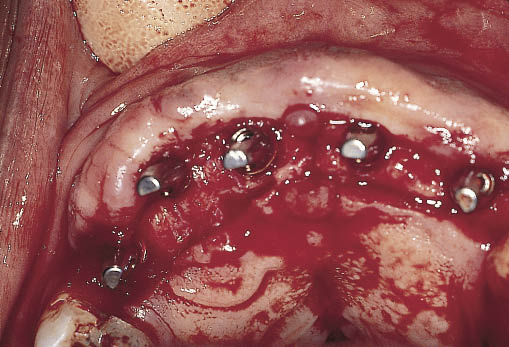
Fig 14-29 Maxillary ridge exposed via a full-thickness incision situated towards the palatal aspect of the ridge. The abutments selected at first-stage surgery have been attached and can be seen.
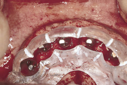
Fig 14-30 The diagnostic template is used to confirm the position of the abutments in relation to future tooth position. Adequate clearance on the labial and palatal aspects must be allowed. The abutments can be seen emerging in tooth position.
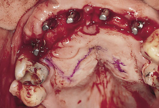
Fig 14-31 Occlusal view of the operative site showing a line marking the extent of the split-thickness incision that will form the sliding epithelial flap to cover the exposed bone.
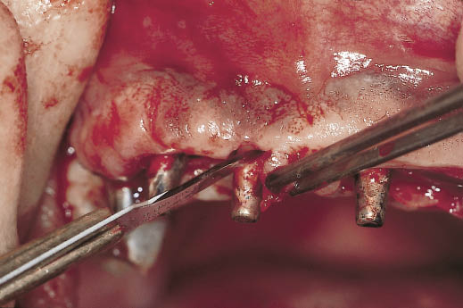
Fig 14-32 ‘S’-shaped incisions being carried out to create pedicled flaps for the reconstruction of the interdental papillae.
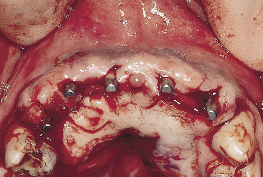
Fig 14-33 Clinical view showing the positioning of the pedicle flaps and the closure of the exposed bone by means of the palatal sliding split-thickness epithelial flap.
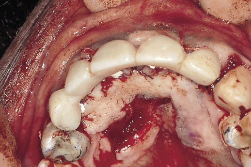
Fig 14-34 The transitional restoration is relined to adapt closely to the abutments and shaped to start the development of the soft tissue contours. The transitional restoration is cemented with a temporary cement. The extent to which the flap has been displaced towards the labial from the palate can be seen.
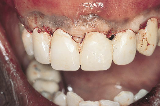
Fig 14-35 Labial view of the transitional restoration showing the contours, which will help to fashion the soft tissues.
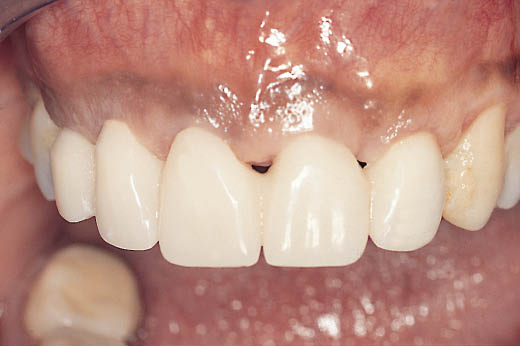
Fig 14-36 Labial view of the healed soft tissues in relationship to the transitional restoration, one month after the exposure of the implants.
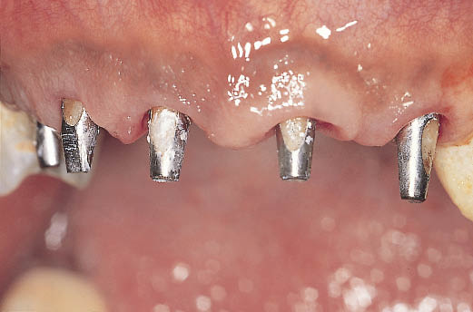
Fig 14-37 Labial view of the abutments emerging from the soft tissues contoured by the transitional restoration.
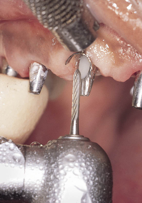
Fig 14-38 Minor modification of the abutment is carried out to prepare a margin to which the dental technician can work. A gingival retractor is used to protect the soft tissues. Modification is carried out using a 12-fluted tungsten carbide bur with copious irrigation.
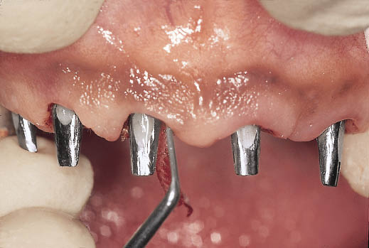
Fig 14-39 Retraction cord is used to ensure an accurate recording of the prepared margins with the impression.
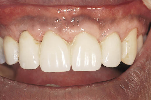
Fig 14-40 The transitional restoration is cleaned to remove traces of temporary cement and relined using self-polymerising resin to re-adapt it to the abutments and to manipulate the soft tissues.
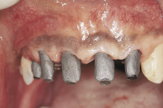
Fig 14-41 Labial view of the metalwork being tried in and ready for a pick-up impression. The shape of the developed soft tissues is thereby recorded for the addition of porcelain to the metal copings.
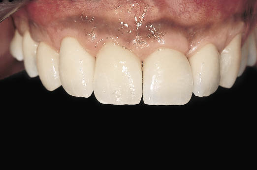
Fig 14-42 Labial view of the definitive metal-ceramic crowns emerging from the reconstructed hard and soft tissues. The deficiency visible in the lateral view relating the provisional metal-acrylic bridge to the postextraction soft tissues has been repaired (Fig 14-18). The provisional bridge also provided information for the implants to be positioned ideally to support the teeth in an aesthetically and functionally verified position (same patient as in Figs 8-37–8-41).
Case 2: Bone Graft from the Iliac Crest for a Class V Ridge
This case study illustrates the treatment of a 60-year-old woman who had lost her anterior maxillary teeth and posterior mandibular teeth. The destruction of the maxillary alveolar ridge may have been the result of a para-functional habit in combination with the pattern of tooth loss.
The resultant Class V ridge (Cawood and Howell50) required treatment with an onlay cortico-cancellous graft obtained from the iliac crest to increase the height of the ridge by 15 mm. Surgery to reconstruct the maxilla was carried out jointly with John Cawood, a consultant oral and maxillofacial surgeon. Onlay grafts were used to reconstruct the anterior maxilla, and bilateral sinus lifts were carried out to create an adequate volume of bone in the posterior quadrants.
The grafts were harvested from the anterior iliac crest by Harbhajan Plaha, a consultant orthopaedic surgeon. Preoperative assessment and perioperative care and general anaesthesia was provided by Michael Boscoe (Figs 14-43–14-49).
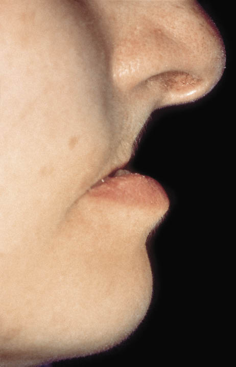
Fig 14-43 Preoperative view of a patient, showing loss of support for the upper lip resulting from the complete destruction of the alveolar ridge. Adequate support of the lower lip is provided by the remaining mandibular incisors.

Fig 14-44 Oblique cross-sectional view of the CT scan of the maxilla in the central incisor region showing the complete loss of the alveolar process. The scan shows a limited amount of bone available for the fixation of the graft. The registration block, which is barely visible, and the mandibular incisor, which can be seen at the bottom of the image, give an indication of the amount of bone loss.
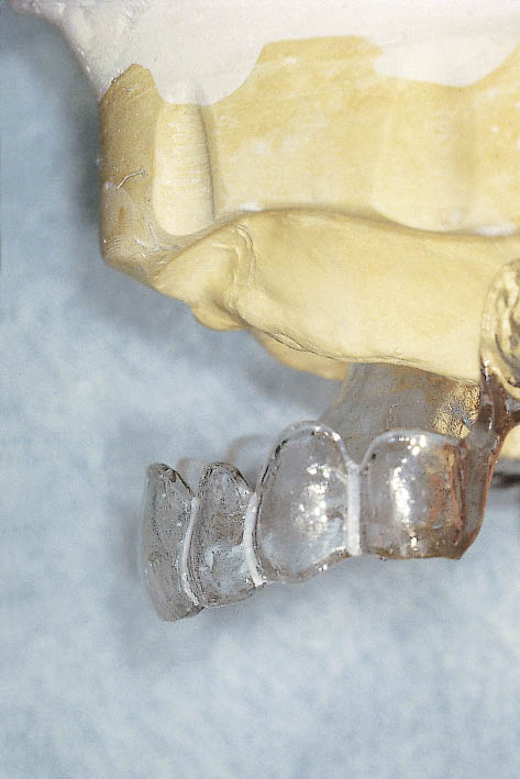
Fig 14-45 A laboratory cast with a diagnostic template constructed from the teeth set up and used to determine the desired end result as a part of the diagnostic preview. The dimensions of the graft are determined preoperatively by relating the tooth position to the residual ridge. Silicone templates are used to relate this information to the surgical site.
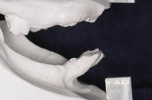
Fig 14-46 Articulated study casts providing information about the anterior–posterior relationship of the upper ridge to the mandibular incisors.
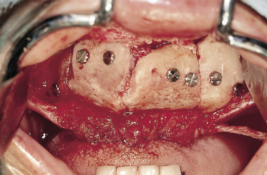
Fig 14-47 Onlay grafts secured into place with screws prior to closure of the surgical site. The flap created by a remote labial incision behind the vermilion border can be seen. (Surgery was carried out jointly with J. Cawood, consultant maxillofacial surgeon, Chester, UK. Bone grafts were harvested by H. Plaha; anaesthesia by M. Boscoe.)
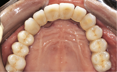
Fig 14-48 Occlusal view of the completed full arch fixed restoration constructed from metal and porcelain.
Stay updated, free dental videos. Join our Telegram channel
VIDEdental - Online dental courses


