Class I, II, and VI Amalgam Restorations
Lee W. Boushell, Theodore M. Roberson and Aldridge D. Wilder, Jr.
Amalgam is used for the restoration of many carious or fractured posterior teeth and in the replacement of failed restorations. Understanding the physical properties of amalgam and the principles of tooth preparation is necessary to produce amalgam restorations that provide optimal service. If properly placed, an amalgam restoration provides many years of service.1–6 Although improved techniques and materials are available, amalgam failures do occur. Much clinical time is spent replacing restorations that fail as a result of recurrent caries, marginal deterioration (i.e., ditching), fractures, or poor contours.7,8 Attention to detail throughout the procedure can significantly decrease the incidence of failures, however, and extend the life of any restoration.9–11 Careful evaluation of existing amalgams is important because they have the potential to provide long-term clinical service and should not be replaced unless an accurate diagnosis is made.12
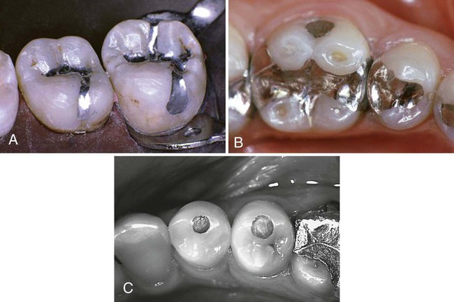
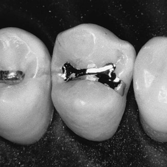
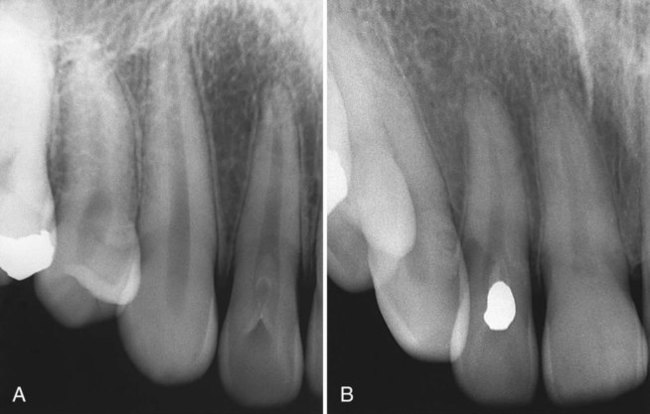
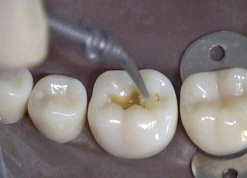
This chapter presents the techniques and procedures for Class I, II, and VI amalgam restorations (Fig. 14-1). Class I restorations restore defects on the occlusal surface of posterior teeth, the occlusal thirds of the facial and lingual surface of molars, and the lingual surfaces of maxillary anterior teeth. Class II restorations restore defects that affect one or both of the proximal surfaces of posterior teeth. Class VI restorations restore rare defects affecting the cusp tips of posterior teeth or the incisal edges of anterior teeth.
Clinical Technique for Class I Amalgam Restorations
This section describes the use of amalgam in conservative and extensive Class I restorations.
Conservative Class I Amalgam Restorations
Conservative tooth preparation is recommended to protect the pulp, preserve the strength of the tooth, and reduce deterioration of the amalgam restoration.17–21 Such conservative preparation saves the tooth structure, minimizing pulpal irritation and leaving the remaining tooth crown as strong as possible.22,23 Conservative preparation also enhances marginal integrity and restoration longevity.20,21,24 The procedural description for a small, conservative Class I amalgam restoration clearly and simply presents the basic information relating to the entire amalgam restoration technique, including tooth preparation and placement and contouring of the restoration. This basic procedural information can be expanded to describe extensive Class I restorations where amalgam use may be indicated.
Initial Clinical Procedures
After the onset of profound anesthesia, isolation with the rubber dam is recommended to gain control over the operating field and for mercury hygiene.25,26 For a single maxillary tooth, where caries is not extensive, adequate control of the operating field may be achieved with cotton rolls and high-volume evacuation. A pre-operative assessment of the occlusal relationship of the involved and adjacent teeth also is necessary.
Tooth Preparation
Initial Tooth Preparation
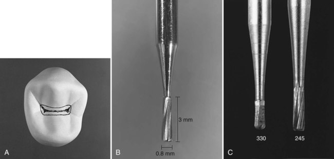
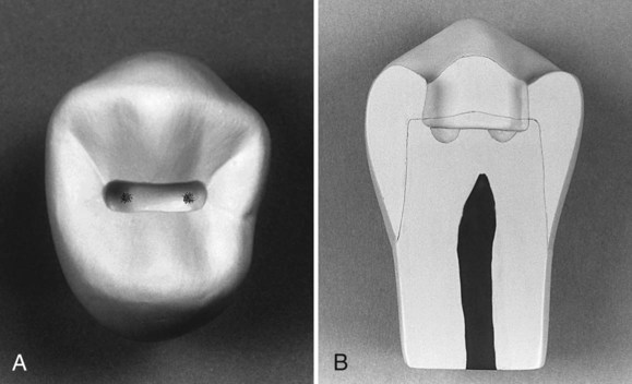
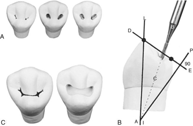
Initial tooth preparation is defined as establishing the outline form by extension of the external walls to sound tooth structure while maintaining a specified, limited depth (usually just inside the dentinoenamel junction [DEJ]) and providing resistance and retention forms. The outline form for the Class I occlusal amalgam tooth preparation should include only the defective occlusal pits and fissures (in a way that sharp angles in the marginal outline are avoided). The ideal outline form for a conservative amalgam restoration (Fig. 14-2, A) incorporates the following resistance form principles that are basic to all amalgam tooth preparations of occlusal surfaces. These principles allow margins to be positioned in areas that are sound and subject to minimal forces while conserving structure to maintain the strength and health of the tooth. The resistance principles are as follows:
 Extending around the cusps to conserve tooth structure and prevent the internal line angles from approaching the pulp horns too closely
 Keeping the facial and lingual margin extensions as minimal as possible between the central groove and the cusp tips
 Extending the outline to include fissures, placing the margins on relatively smooth, sound tooth structure
 Minimally extending into the marginal ridges (only enough to include the defect) without removing dentinal support
 Eliminating a weak wall of enamel by joining two outlines that come close together (i.e., <0.5 mm apart)
 Extending the outline form to include enamel undermined by caries
 Using enameloplasty on the terminal ends of shallow fissures to conserve tooth structure
 Establishing an optimal, conservative depth of the pulpal wall
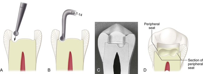
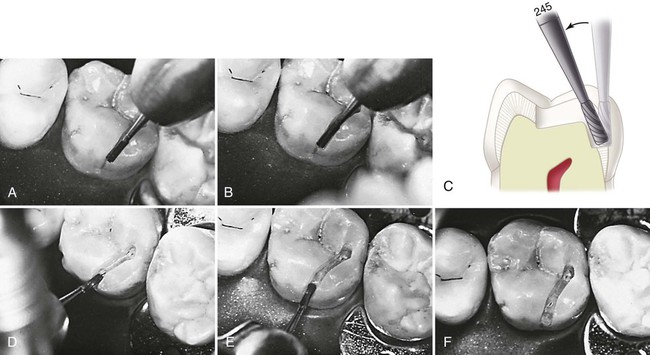
A No. 245 bur with a head length of 3 mm and a tip diameter of 0.8 mm or a smaller No. 330 bur is recommended to prepare the conservative Class I tooth preparation (Fig. 14-2, B and C). The silhouette of the No. 245 bur reveals sides slightly convergent toward the shank. This produces an occlusal convergence of the facial and lingual preparation walls, providing adequate retention form for the tooth preparation. The slightly rounded corners of the end of the No. 245 bur produce slightly rounded internal line angles that render the tooth more resistant to fracture from occlusal force.27 The No. 330 bur is a smaller version of the No. 245 bur. It is indicated for the most conservative amalgam preparations (see Fig. 14-2, C).
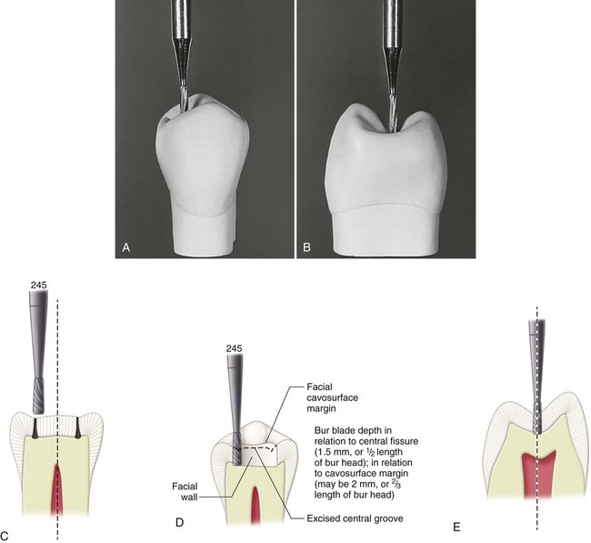
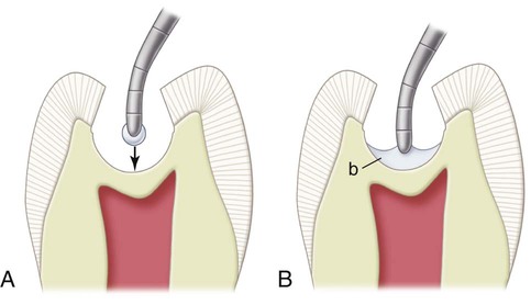
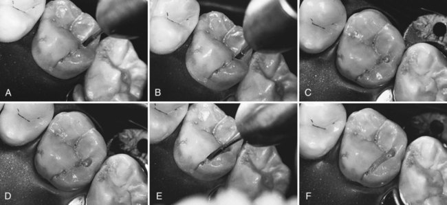
Class I occlusal tooth preparation is begun by entering the deepest or most carious pit with a punch cut using the No. 245 carbide bur at high speed with air-water spray.28 A punch cut is performed by orienting the bur such that its long axis parallels the long axis of the tooth crown (Fig. 14-3, A and B). The bur is inserted directly into the defective pit. When the pits are equally defective, the distal pit should be entered as illustrated. Entering the distal pit first provides increased visibility for the mesial extension. The bur should be positioned such that its distal aspect is directly over the distal pit, minimizing extension into the marginal ridge (see Fig. 14-3, C). The bur should be rotating when it is applied to the tooth and should not stop rotating until it is removed from the tooth. Dentinal caries initially spreads at the DEJ; therefore, the goal of the initial cut is to reach the DEJ. On posterior teeth, the approximate depth of the DEJ is located at 1.5 to 2 mm from the occlusal surface. As the bur enters the pit, an initial target depth of 1.5 mm should be established. This is one-half the length of the cutting portion of the No. 245 bur. The 1.5 mm pulpal depth is measured at the central fissure (Fig. 14-3, D and E). Depending on the cuspal incline, the depth of the prepared external walls is 1.5 to 2 mm (Fig. 14-3, D and E). The depth of the preparation is modified as needed so that the pulpal wall is established 0.1-0.2 mm into dentin. The length of the blades of an unfamiliar entry bur should be measured before it is used as a depth gauge.
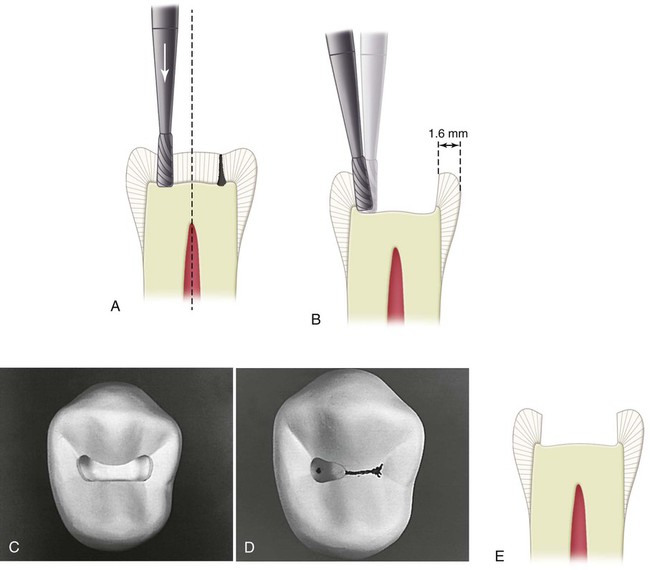
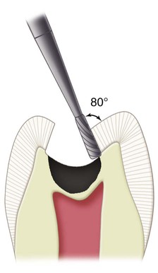
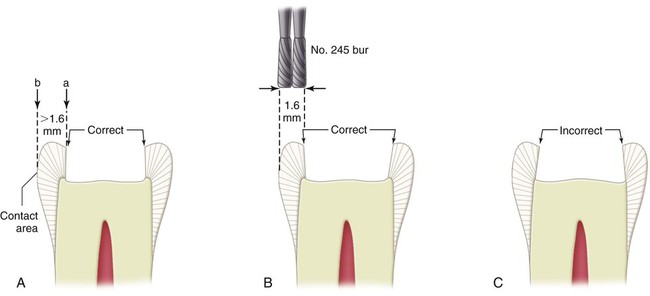
Distal extension into the distal marginal ridge to include a fissure or caries occasionally requires a slight tilting of the bur distally (≤10 degrees). This creates a slight occlusal divergence to the distal wall to prevent undermining the marginal ridge of its dentin support (Fig. 14-4, A through C). Because the facial and lingual prepared walls converge, this slight divergence does not present any retention form concerns. For premolars, the distance from the margin of such an extension to the proximal surface usually should not be less than 1.6 mm, or two diameters of the end of the No. 245 bur (Fig. 14-4, B) measured from a tangent to the proximal surface (i.e., the proximal surface height of contour). For molars, this minimal distance is 2 mm. A minimal distal (or mesial) extension often does not require changing the orientation of the bur’s axis from being parallel to the long axis of the tooth crown; the mesial and distal walls are parallel to the long axis of the tooth crown (or slightly convergent occlusally).
While maintaining the bur’s orientation and depth, the preparation is extended distofacially or distolingually to include any fissures that radiate from the pit (see Fig. 14-4, D). When these fissures require extensions of more than a few tenths of a millimeter, however, consideration should be given to changing to a bur of smaller diameter, or to using enameloplasty. Both of these approaches conserve the tooth structure and minimize weakening of the tooth.
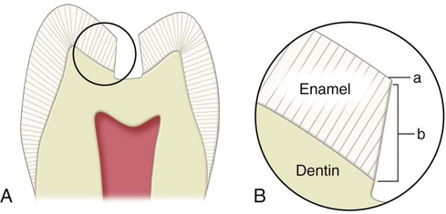
The bur’s orientation and depth are maintained while extending along the central fissure toward the mesial pit, following the DEJ (see Fig. 14-4, E). When the central fissure has minimal caries, one pass through the fissure at the prescribed depth provides the desired minimal width to the isthmus. Ideally, the width of the isthmus should be just wider than the diameter of the bur. It is well established that a tooth preparation with a narrow occlusal isthmus is less prone to fracture.29,30 As previously described for the distal margin, the orientation of the bur should not change as it approaches the mesial pit if the mesial extension is minimal. If the fissure extends farther onto the marginal ridge, the long axis of the bur should be changed to establish a slight occlusal divergence to the mesial wall if the marginal ridge would be otherwise undermined of its dentinal support. Figure 14-5 illustrates the correct and incorrect preparation of the mesial and distal walls. The remainder of any occlusal enamel defects is included in the outline, and the facial and lingual walls are extended, if necessary, to remove enamel undermined by caries.31 The strongest and ideal enamel margin should be composed of full-length enamel rods attached to sound dentin, supported on the preparation side by shorter rods, also attached to sound dentin (Fig. 14-6).
The conservative Class I tooth preparation should have an outline form with gently flowing curves and distinct cavosurface margins. A faciolingual width of no more than 1 to 1.5 mm and a depth of 1.5 to 2 mm are considered ideal, but this goal is subject to the extension of the caries. The pulpal floor, depending on the enamel thickness, is almost always in dentin (see Fig. 14-4, C). Although conservation of the tooth structure is important, the convenience form requires that the extent of the preparation provides adequate access and visibility.
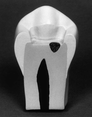
This completes the initial amalgam preparation for Class I caries. The extension should ensure that all caries is removed from the DEJ, resulting in a very narrow peripheral seat of healthy dentin on the pulpal wall surrounding the caries. For the initial tooth preparation, the pulpal wall should remain at the initial ideal depth, even if any restorative material or caries remains in the central area of the pulpal wall (Fig. 14-7). The remaining caries (and usually old restorative material) is removed during the final tooth preparation.
The primary resistance form is provided by the following:
 Sufficient area of relatively flat pulpal floor in sound tooth structure to resist forces directed in the long axis of the tooth and to provide a strong, stable seat for the restoration
 Minimal extension of external walls, which reduces weakening of the tooth
 Sufficient depth (i.e., 1.5 mm) that results in adequate thickness of the restoration, providing resistance to fracture and wear
Usually, the No. 245 bur is used for extensions into the mesial and distal fissures. During such extensions, the remaining depth of the fissure can be viewed in cross-section by looking at the wall being extended. When the remaining fissure is no deeper than one-quarter to one-third the thickness of enamel, enameloplasty is indicated. Enameloplasty refers to eliminating the developmental fault by removing it with the side of a flame-shaped diamond stone, leaving a smooth surface (Fig. 14-8, A through C). This procedure frequently reduces the need for further extension. The extent to which enameloplasty should be used cannot be determined exactly until the process of extending into the fissured area occurs, at which time the depth of the fissure into enamel can be observed. The surface left by enameloplasty should meet the tooth preparation wall, preferably with a cavosurface angle no greater than approximately 100 degrees; this would produce a distinct margin for amalgam of no less than 80 degrees (see Fig. 14-8, D). During carving, amalgam should be removed from areas of enameloplasty. Otherwise, thin amalgam left in these areas may fracture because of its low edge strength. If enameloplasty is unsuccessful in eliminating a mesial (or distal) fissure that extends to the crest of a marginal ridge or beyond, three alternatives exist:
Final Tooth Preparation
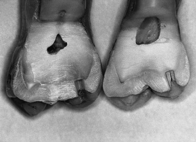
If several enamel pit-and-fissure remnants remain in the floor, or if a central fissure remnant extends over most of the floor, the floor should be deepened with the No. 245 bur to eliminate the defect or to uncover the caries (Fig. 14-10). If these remnants are few and small, they can be removed with an appropriate carbide bur (Fig. 14-11). Removal of the remaining infected dentin (i.e., caries that extends pulpally from the established pulpal floor) is best accomplished using a discoid-type spoon excavator or a slowly revolving round carbide bur of appropriate size (Fig. 14-12, A and B). Using the largest instrument that fits the carious area is safest because it is least likely to penetrate the tooth in an uncontrolled manner. When removing infected dentin, the excavation should be stopped when the tooth structure feels hard or firm (i.e., the same feel as sound dentin). This situation often occurs before all lightly stained or discolored dentin is removed.32 A sharp explorer or hand instrument is more reliable than a rotating bur for judging the adequacy of removal of infected dentin. These instruments should be used judiciously, however, in areas of possible pulpal exposure.
The removal of carious dentin should not affect the resistance form further because the periphery would not need further extension. In addition, it should not affect the resistance form if the restoration is to rest on the pulpal wall peripheral to the excavated area or areas. The peripheral pulpal floor should be at the previously described initial pulpal floor depth just inside the DEJ (see Fig. 14-12, C and D).
If the tooth preparation is of ideal or shallow depth, no liner or base is indicated. In deeper caries excavations (where the remaining dentin thickness is judged to be 0.5 to 1 mm), a thin layer (i.e., 0.5–0.75 mm) of a light-activated, resin-modified glass ionomer (RMGI) material should be placed.33,34 The RMGI insulates the pulp from thermal changes, bonds to dentin, releases fluoride, is strong enough to resist the forces of condensation, and reduces microleakage.34–36 The RMGI is applied only over the deepest portion of the excavation. The entire dentin surface should not be covered (Fig. 14-13). Dentin peripheral to the liner should be available for support of the restoration.37 The external walls already have been finished during earlier steps in this conservative tooth preparation for amalgam. An occlusal cavosurface bevel is contraindicated in the tooth preparation for an amalgam restoration.38 It is important to provide an approximate 90- to 100-degree cavosurface angle, which should result in 80- to 90-degree amalgam at the margins.31 This butt-joint margin of enamel and amalgam is the strongest for both. Amalgam is a brittle material with low edge strength and tends to chip under occlusal stress if its angle at the margins is less than 80 degrees.
The completed tooth preparation should be inspected and cleaned before restoration. The tooth preparation should be free of debris after the tooth has been rinsed with the air-water syringe. Disinfectants that are available may be used for cleaning the tooth preparation, but this is not considered essential.28,39 A cotton pellet or a commercially available applicator tip moistened only with water is generally used.
Other Conservative Class I Amalgam Preparations
 Facial pit of the mandibular molar
 Lingual pit of the maxillary lateral incisor
 Occlusal pits of the mandibular first premolar
 Occlusal pits and fissures of the maxillary first molar
 Occlusal pits and fissures of the mandibular second premolar
Examples of some of these types of preparations and restorations are provided in Figures 14-14 through 14-19.
Restorative Technique for Class I Amalgam Preparations
Desensitizer Placement
A dentin desensitizer is placed in the preparation before amalgam condensation (Fig. 14-20).40 The dentin desensitizer is applied onto the prepared tooth surface according to manufacturer’s recommendations; excess moisture is removed without desiccating the dentin; and then the amalgam is condensed into place. The dentin desensitizer precipitates protein and forms lamellar plugs in the dentinal tubules.41 These plugs are thought to be responsible for reducing the permeability and sensitivity of dentin. Dentin may not be totally sealed by a desensitizing agent because no hybrid layer is formed as in bonding procedures. If amalgam adhesives are used, a separate desensitizing agent is usually unnecessary. However, concerns exist about the long-term durability of amalgam adhesives and whether resin adhesives may interfere with the self-sealing capability of the amalgam.15,42–44
Insertion and Carving of The Amalgam
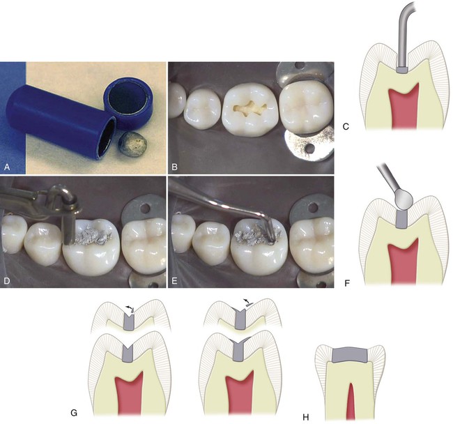
Because of its superior clinical performance, high-copper amalgam is recommended. Pre-proportioned, disposable capsules are available in sizes ranging from 400 to 800 mg. Some pre-capsulated brands require activation of the capsules before trituration. Amalgam should be triturated (i.e., mixed) according to the manufacturer’s directions. It is often necessary to make several mixes to complete the restoration, particularly for large preparations. The triturated amalgam is emptied into an amalgam well (Fig. 14-21, A). Correctly mixed amalgam should not be dry and crumbly. It has a minimal, yet sufficient, “wetness” to aid in achieving a homogeneous and well-adapted restoration.25
The principal objectives during the insertion of amalgam are to condense the amalgam to adapt it to the preparation walls and the matrix (when used) and produce a restoration free of voids. Thorough condensation helps to reduce marginal leakage.45,46 Optimal condensation also is necessary to minimize the mercury content in the restoration to decrease corrosion and to enhance strength and marginal integrity.47 Condensation of amalgam that contains spherical particles requires larger condensers than are commonly used for admixed amalgam. Smaller condensers tend to penetrate a mass of spherical amalgam, resulting in less effective force to compact or adapt the amalgam within the preparation. In contrast, smaller condensers are indicated for the initial increments of admixed amalgam because it is more resistant to condensation pressure. Because the area of a circular condenser face increases by the square of the diameter, doubling the diameter requires four times more force for the same pressure on a unit area.
The outline of the tooth preparation should be reviewed before inserting amalgam to allow the formation of a mental image that will later aid in carving amalgam to the cavosurface margin. Pre-operative occlusal contact locations should be recalled (see Fig. 14-21, B). An amalgam carrier is used to transfer amalgam to the tooth preparation. Increments extruded from the carrier should be smaller (often only 50% or less of a full-carrier tip) for a small preparation, particularly during the initial insertion. A flat-faced, circular or elliptic condenser should be used to condense amalgam over the pulpal floor of the preparation. Amalgam should be carefully condensed into the pulpal line angles (see Fig. 14-21, C). Usually, a smaller condenser is used while filling the preparation and a larger one for over-packing. Each portion is thoroughly condensed prior to placement of the next increment. Each condensed increment should fill only one-third to one-half the preparation depth. Each condensing stroke should overlap the previous condensing stroke to ensure that the entire mass is well condensed. The condensation pressure required depends on the amalgam used and the diameter of the condenser nib. Condensers with larger diameter nibs require greater condensation pressure. The preparation should be over-packed 1 mm or more using heavy pressure (see Fig. 14-21, D); this ensures that the cavosurface margins are completely covered with well-condensed amalgam. Final condensation over cavosurface margins should be done perpendicular to the external enamel surface adjacent to the margins.
To ensure that the marginal amalgam is well condensed before carving, the over-packed amalgam should be burnished immediately with a large burnisher, using heavy strokes mesiodistally and faciolingually, which is referred to as precarve burnishing. To maximize its effectiveness, the burnisher head should be large enough that in the final strokes, it contacts the cusp slopes but not the margins (see Fig. 14-21, E). Pre-carve burnishing produces denser amalgam at the margins of the occlusal preparations restored with high-copper amalgam alloys and initiates contouring of the restoration.48,49
Contouring and Finishing of THE Amalgam
With care, carving may begin immediately after condensation. Sharp discoid–cleoid carvers of suitable sizes are recommended. The larger end of the discoid-cleoid instrument (No. 3–No. 6) is used first, followed by the smaller instrument (No. 4 or No. 5) in regions not accessible to the larger instrument. Alternatively, the Hollenback carver can be used. All carving should be done with the edge of the blade perpendicular to the margins as the instrument is moved parallel to the margins. Part of the edge of the carving blade should rest on the unprepared tooth surface adjacent to the preparation margin (see Fig. 14-21, F). Using this surface as a guide helps prevent over-carving amalgam at the margins and to produce a continuity of surface contour across the margins.
Deep occlusal grooves should not be carved into the restoration because these may thin the amalgam at the margins, invite chipping, and weaken the restoration (see Fig. 14-21, G). Under-carving leaves thin portions of amalgam (subject to fracture) on the unprepared tooth surface. The thin portion of amalgam extending beyond the margin is referred to as flash. The mesial and distal fossae should be carved slightly deeper than the proximal marginal ridges (see Fig. 14-21, H).
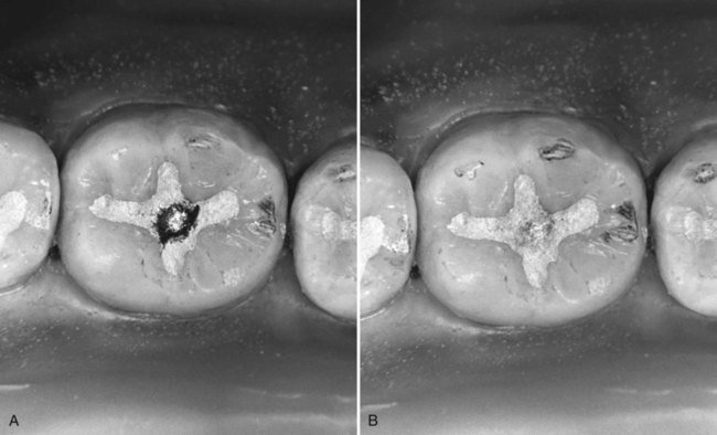
After carving is completed, the outline of the amalgam margin should reflect the contour and location of the prepared cavosurface margin. An amalgam outline that is larger or irregular is under-carved and requires further carving or finishing (Fig. 14-22). An amalgam restoration that is more than minimally over-carved (i.e., a submarginal defect >0.2 mm) should be replaced.50 If the total carving time is short enough, the smoothness of the carved surface may be improved by wiping with a small, damp ball of cotton held in the operating pliers. All shavings from the carving procedure should be removed from the mouth with the aid of the oral evacuator.

Some operators prefer to perform post-carve burnishing of the amalgam surface by using a small burnisher. Post-carve burnishing is done by lightly rubbing the carved surface with a burnisher of suitable size and shape to improve smoothness and produce a satin (not shiny) appearance. The surface should not be rubbed hard enough to produce grooves in the amalgam. Post-carve burnishing may improve the marginal integrity of low- and high-copper amalgams and may improve the smoothness of the restoration.51,52 Post-carve burnishing in conjunction with pre-carve burnishing may serve as a viable substitute for conventional polishing.53
1. Cusp tips of adjacent teeth are not in occlusal contact when it is known from the pre-operative occlusal assessment that they should be touching.
2. A cusp that occludes with the new restoration contacts prematurely.
Any contact area can be recognized on the amalgam by the depth of color imparted by the paper (and especially if the colored area has a silvery center). The deeper-colored or shiny-centered areas are reduced until all markings are uniformly of a light hue (and with no shiny centers), and contacts are noted on adjacent teeth (Fig. 14-23). Observing the space (short of touching) between surfaces of nearby teeth indicates how much to reduce when carving. If these opposing surfaces are 0.5 mm apart (by visual estimation), the high area should be reduced by approximately that amount. This expedites the occlusal adjustment compared with making an insufficient, shallower carving adjustment and then having to repeat closure and carving numerous times. The sequence of closure, observation, and carving is repeated until the appropriate surfaces of opposing teeth are touching. Carving should be accomplished so that opposing cusps contact on a surface that is perpendicular to the occlusal forces in maximum intercuspation. Occlusal contacts located on a cuspal incline or ridge slope are undesirable because they cause a deflective force on the tooth and should be adjusted until the resulting contact is stable (i.e., the force vector of the occlusal contacts should parallel the long axis of the tooth). The final anatomy of the restoration should be patterned after normal occlusal contours. The tip of an explorer should pass from the tooth surface to the restoration surface (and vice versa), without jumping or catching, thus verifying continuity of contour across the margin.
Most amalgams do not require further finishing and polishing. These procedures are occasionally necessary, however, to (1) complete the carving; (2) refine the anatomy, contours, and marginal integrity; and (3) enhance the surface texture of the restoration. Additional finishing and polishing procedures for amalgam restorations are not attempted within 24 hours of insertion because crystallization is incomplete.25 If used, these procedures are often delayed until all of the patient’s amalgam restorations have been placed, rather than finishing and polishing periodically during the course of treatment. An amalgam restoration is less prone to tarnish and corrosion if a smooth, homogeneous surface is achieved.25,31,54 Polishing of high-copper amalgams is less important than it is for low-copper amalgams because high-copper amalgams are less susceptible to tarnishing and marginal breakdown.5,55–60
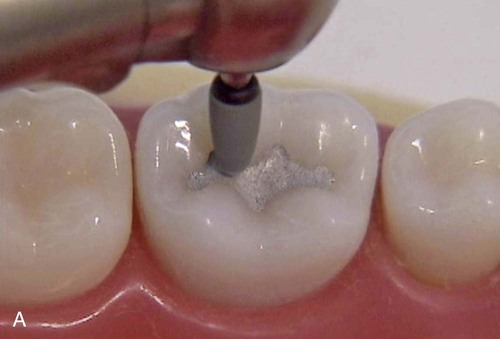
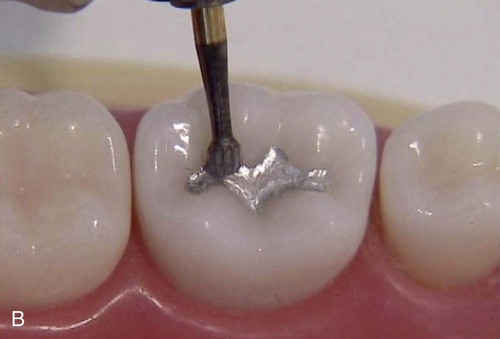
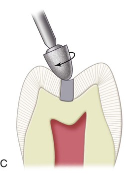
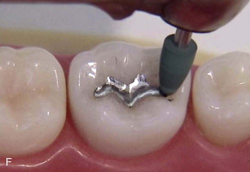
The finishing procedure is initiated by marking the occlusion with articulating paper and evaluating the margins with an explorer. If the occlusion can be improved, or a continuity of surface contour across the margins is not present, a white alumina stone or a green carborundum stone is used to correct the discrepancy (Fig. 14-24, A). The green stone is more abrasive than the white stone; the tip of either stone may be blunted on a diamond wheel before use. This helps prevent marring the center of the restoration while the margins are being adjusted. During the surfacing of amalgam, the stone’s long axis is held at a 90-degree angle to the margins. Reduction of any occlusal contact should be avoided. After the stone is used, the margins should be re-evaluated with an explorer tine. If no discrepancy is detected, the area may be smoothed further using light pressure with an appropriate finishing bur (see Fig. 14-24, B). A large, round finishing bur (comparable with a No. 4 or No. 6) is generally used for this finishing step. If the groove and fossa features are not sufficiently defined, a small round finishing bur also may accentuate them without reducing the centric holding areas. The long axis of the bur or stone should be at a 90-degree angle to the margin to allow the unprepared tooth structure to guide the bur and prevent unnecessary removal of amalgam (see Fig. 14-24, C). A smooth surface should be achieved before the polishing procedure is initiated. The finishing bur should remove the minor scratches which resulted from use of the green or white stone. Often, however, these scratches can be removed only with the use of a rubber abrasive point.
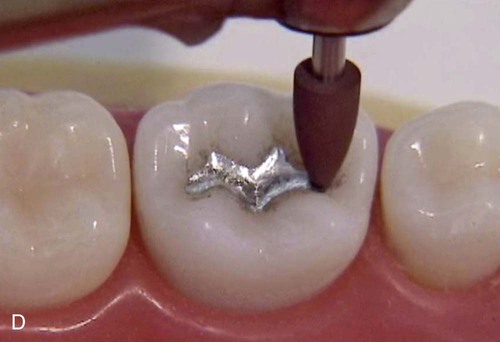
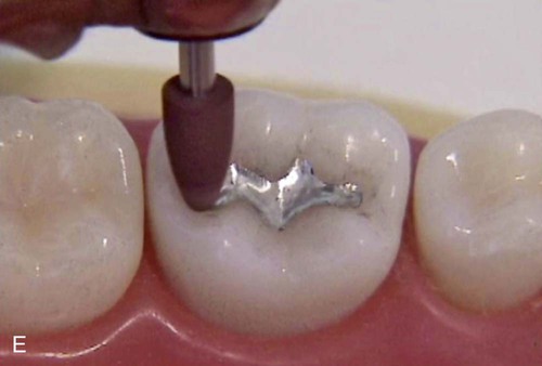
The polishing procedure is started by using a coarse, rubber abrasive point at low speed and air-water spray to produce an amalgam surface with a smooth, satiny appearance (see Fig. 14-24, D and E). If the amalgam surface does not exhibit this appearance after only a few seconds of polishing, the surface was too rough at the start. In this instance, resurfacing with a finishing bur is necessary, followed by the coarse, rubber abrasive point to develop the satiny appearance. It is important that the rubber points be used at low speed or just above “stall out” speed for two reasons:
1. The danger of the point disintegrating at high speeds
2. The danger of elevating the temperature of the restoration and the tooth
An excessive temperature increase (i.e., >140°F [>60°C]) can cause irreparable damage to the pulp, the restoration, or both. When overheated, the amalgam surface appears cloudy, even though it may have a high polish. This cloudy appearance indicates that mercury has been brought to the surface, which results in corrosion of the amalgam and loss of strength.25
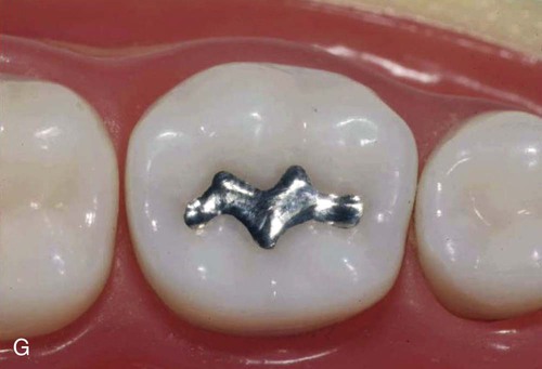
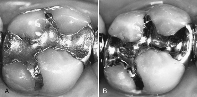
After polishing with the coarse, abrasive rubber point, no deep scratches should remain on the amalgam surface, only the moderately polished surface left by the rubber point. After the area is washed free of abrasive particles, a high polish may be imparted to the restoration with a series of medium-grit and fine-grit abrasive points (see Fig. 14-24, F). As with the more abrasive points, the finer abrasive points must be used at a low speed. If a high luster does not appear within a few seconds, the restoration requires additional polishing with the more abrasive points. The system that is illustrated includes coarse-grit, medium-grit, and fine-grit rubber abrasive points. Using these points in sequence, from coarse to fine, produces an amalgam surface with a brilliant luster (see Fig. 14-24, G). As an alternative to rubber abrasive points, final polishing may be accomplished using a rubber cup with flour of pumice followed by a high-luster agent, such as precipitated chalk. Finishing and polishing of older, existing restorations may be performed to improve their contour, margins, surface, or anatomy, when indicated (Fig. 14-25).
Extensive Class I Amalgam Restorations
Caries is considered extensive if the distance between infected dentin and the pulp is judged to be less than 1 mm or when the faciolingual extent of the defect is up the cuspal inclines. Extensive caries requires a more extensive restoration (which is a more typical indication for amalgam). The use of amalgam in large Class I restorations provides good wear resistance and occlusal contact relationships. For very large Class I restorations, a bonding system may be used, although this book no longer promotes such use. The perceived benefits of bonded amalgams have not been substantiated.58,61–63 Bonded amalgams have no advantages compared with the conventional technique, when done correctly.
Initial Clinical Procedures
The rubber dam should be used for isolation of the operating site when caries is extensive. If caries excavation exposes the pulp, pulp capping may be more successful if the site is isolated with a properly applied rubber dam. In addition, the dam prevents moisture contamination of the amalgam mix during insertion.25
Tooth Preparation
Initial Tooth Preparation
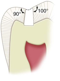
In teeth with extensive caries, excavation of infected dentin and, if necessary, insertion of a liner may precede the establishment of the outline, resistance, and retention forms. This approach protects the pulp as early as possible from any additional insult of tooth preparation. Normally, however, the outline form and the primary resistance and retention forms are established through proper orientation of the No. 245 bur and preparation extension. An initial depth to reach the DEJ (measured approximately 1.5 mm at any pit or fissure and 2 mm on the prepared external walls) should be established and maintained. The preparation is extended laterally at the DEJ to remove all enamel undermined by caries by alternately cutting and examining the lateral extension of the caries. For caries extending up the cuspal inclines, it may be necessary to alter the bur’s long axis to prepare a 90- to 100-degree cavosurface angle while maintaining the initial depth (Fig. 14-26). If not, a significantly obtuse cavosurface angle may remain (resulting in an acute, or weak, amalgam margin), or the pulpal floor may be prepared too deeply. The primary resistance form is obtained by extending the outline of the tooth preparation to include only undermined and defective tooth structure while preparing strong enamel walls and allowing strong cuspal areas to remain. Primary retention is obtained by the occlusal convergence of the enamel walls; the secondary retention form may result from undercut areas that are occasionally left in dentin (and that are not covered by a liner) after removal of infected dentin.
When extending the outline form, enameloplasty should be used, when possible (as described previously). When the defect extends to more than one-half the distance between the primary groove and a cusp tip, capping the cusp (i.e., reducing the cuspal tooth structure and restoring it with amalgam) may be indicated. When that distance is two-thirds, cusp capping usually is required because of the risk of cusp fracture postoperatively. Figure 14-27 illustrates some examples of large Class I amalgam preparation outlines.
Final Tooth Preparation
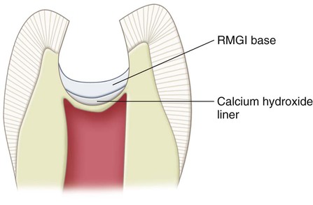
For pulpal protection in very deep caries excavations (where the remaining dentin thickness is judged to be <0.5 mm and a pulpal exposure is suspected), a thin layer (i.e., 0.5–0.75 mm) of a calcium hydroxide liner may be placed. The calcium hydroxide liner may stimulate secondary dentin formation in an area where a micro-exposure is suspected or may elicit tertiary dentin formation if the original odontoblasts were no longer vital. If the calcium hydroxide liner is used, it is placed by using the same instrument and the same technique as described for the RMGI liner. The calcium hydroxide liner should be placed only over the deepest portion of the excavation (nearest the pulp). An RMGI base should be used to cover the calcium hydroxide.47 The entire dentin surface should not be covered (Fig. 14-28). The RMGI base is recommended to cover the calcium hydroxide to resist the forces of condensation and to prevent dissolution over time by sealing the deeply excavated area.35 Usually, no secondary resistance or retention form features are necessary for extensive Class I amalgam preparations. The external walls of the preparation are finished as described previously.
Class I Occlusolingual Amalgam Restorations
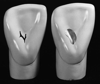
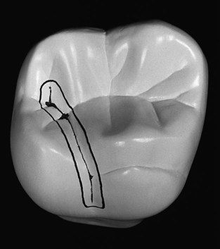
Occlusolingual amalgam restorations may be used on maxillary molars when a lingual fissure connects with the distal oblique fissure and distal pit on the occlusal surface (Fig. 14-29). Composite also may be used as the restorative material, especially in smaller restorations.
Tooth Preparation
 The tooth preparation should be no wider than necessary; ideally, the mesiodistal width of the lingual extension should not exceed 1 mm except for extension necessary to remove carious or undermined enamel or to include unusual fissuring.
 When indicated, the tooth preparation should be cut more at the expense of the oblique ridge, rather than centering over the fissure (weakening the small distolingual cusp).
 Especially on smaller teeth, the occlusal portion may have a slight distal tilt to conserve the dentin support of the distal marginal ridge (Fig. 14-30).
 The margins should extend as little as possible onto the oblique ridge, distolingual cusp, and distal marginal ridge.
These objectives help conserve the dentinal support and the strength of the tooth, and they aid in establishing an enamel cavosurface angle as close to 90 degrees as possible (Fig. 14-31). They also minimize deterioration of the restoration margins by locating the margins away from enamel eminences where occlusal forces may be concentrated.
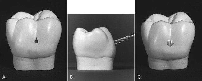
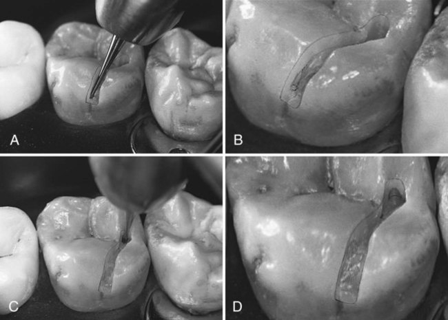
The distal pit is identified with indirect vision and entered with the end of the No. 245 bur (Fig. 14-32, A). The long axis of the bur usually should be parallel to the long axis of the tooth crown. The dentinal support and strength of the distal marginal ridge and the distolingual cusp should be observed, and the bur positioned such that it cuts more of the tooth structure mesial to the pit rather than distal to the pit (e.g., 70 : 30 rather than 50 : 50), if needed. The initial cut is to the level of the DEJ (a depth of 1.5 to 2 mm) (see Fig. 14-32, B). At this depth, the pulpal floor is usually in dentin. When the entry cut is made (see Fig. 14-32, C), the bur (maintaining the initial established depth) is moved to include any remaining fissures facial to the point of entry (see Fig. 14-32, D). The bur is then moved along the fissure toward the lingual surface (see Fig. 14-32, E). As with Class I occlusal preparations, a slight distal inclination of the bur is indicated occasionally (e.g., smaller teeth) to conserve the dentinal support and strength of the marginal ridge and the distolingual cusp. To ensure adequate strength for the marginal ridge, the distopulpal line angle should not approach the distal surface of the tooth closer than 2 mm. On large molars, the bur position should remain parallel to the long axis of the tooth, particularly if the bur is offset slightly mesial to the center of the fissure. Keeping the bur parallel to the long axis of the tooth creates a distal wall with slight occlusal convergence, providing favorable enamel and amalgam angles. The bur is moved lingually along the fissure, maintaining a uniform depth until the preparation is extended onto the lingual surface (see Fig. 14-32, F). The pulpal floor should follow the contour of the occlusal surface and the DEJ, which usually rises occlusally as the bur moves lingually.
The lingual portion is prepared at this point by using one of two techniques. In one technique, the lingual surface is prepared with the bur’s long axis parallel with the lingual surface (see Fig. 14-33, A and B). The tip of the bur should be located at the gingival extent of the lingual fissure. The bur should be controlled so that it does not “roll out” onto the lingual surface, which may “round over” or damage the cavosurface margin. The facial inclination of the bur must be altered as the cutting progresses to establish the axial wall of the lingual portion at a uniform depth of 0.5 mm inside the DEJ (see Fig. 14-33, C). The axial wall should follow the contour of the lingual surface of the tooth. An axial depth of 0.5 mm inside the DEJ is indicated if retentive grooves are required; an axial depth of 0.2 mm inside the DEJ is permissible if retentive grooves are not required.
The No. 245 bur may be used with its long axis perpendicular to the axial wall to accentuate (i.e., refine) the mesioaxial and distoaxial line angles; this also results in the mesial and distal walls converging lingually because of the shape of the bur (see Fig. 14-33, D and E). During this step, the axial wall depth is not altered (see Fig. 14-33, F). The occlusal and lingual convergences usually provide a sufficient preparation retention form; no retention grooves are needed.
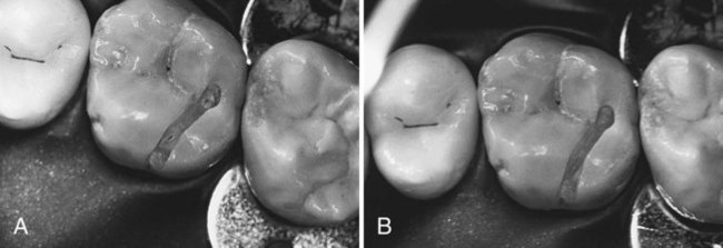
The axiopulpal line angle must be rounded to limit the areas of stress concentration and ensure adequate preparation depth and amalgam thickness (Fig. 14-34). Initial tooth preparation of the occlusolingual preparation is now complete. As mentioned previously, enameloplasty may be performed to conserve the tooth structure and limit extension.
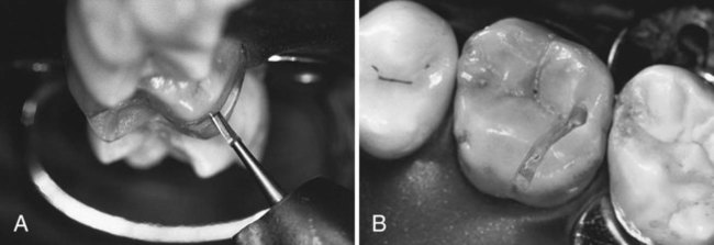
Additional retention in the lingual extension may be required if the extension is wide mesiodistally or if it was prepared without a lingual convergence. If additional retention is required, the No.  or No. 169 bur can be used to prepare grooves into the mesioaxial and distoaxial line angles (Fig. 14-35, A). If these angles are in enamel, the axial wall must be deepened to 0.5 mm axially of the DEJ (because the grooves must be in dentin so as to not undermine enamel). The depth of the grooves at the gingival floor is one-half the diameter of the No.
  bur. The cutting direction for each groove is the bisector of the respective line angle. The groove is slightly deeper pulpally than the correctly positioned axial wall and is 0.2 mm axial to the DEJ. The grooves should diminish in depth toward the occlusal surface, terminating midway along the axial wall (see Fig. 14-35, B). The adequacy of the groove should be tested by inserting the tine of an explorer into the groove and moving it lingually. The mesial or distal depth of the groove should prevent the explorer from being withdrawn lingually. (See the section on secondary resistance and retention forms for a description of placing retentive grooves in the proximal boxes of Class II amalgam preparations; the techniques are similar.)
Extension of a facial occlusal fissure may have required a slight divergence occlusally to the facial wall to conserve support of the facial ridge. If so and if deemed necessary, the  round bur may be used to prepare a retention cove in the faciopulpal line angle (see Fig. 14-35, C and D). The tip of the No. 245 bur held parallel to the long axis of the tooth crown also might be used to prepare this cove. Care should be taken so as not to undermine the occlusal enamel (this retentive cove is recommended only if occlusal convergence of the mesial and distal walls of the occlusal portion is absent or inadequate).
The final tooth preparation is accomplished by removal of remaining caries on the pulpal and axial walls (Fig. 14-36) with an appropriate round bur, a discoid-type spoon excavator, or both. A liner or base (alone or together) is placed in the deep excavations for pulpal protection. The external walls are finished. Any irregularities at the margins may indicate weak enamel that may be removed by the side of the No. 245 bur rotating at slow speed.
Restorative Technique
Matrix Placement (If Necessary)
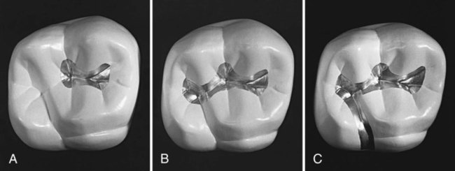
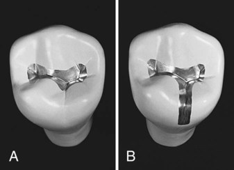
Using a rigid matrix to support the lingual portion of the restoration during condensation is occasionally necessary. A matrix is helpful to prevent “landsliding” during condensation and to ensure marginal adaptation and strength of the restoration. The Tofflemire matrix retainer is used to secure a matrix band to the tooth (as described later). Because this type of matrix band does not intimately adapt to the lingual groove area of the tooth (Fig. 14-37, A), an additional step may be necessary to provide a matrix that is rigid on the lingual portion of the tooth preparation. If so, a piece of stainless steel matrix material (0.002 inch [0.05 mm] thick,  inch [8 mm] wide) is cut to fit between the lingual surface of the tooth and the band already in place (see Fig. 14-37, B). The gingival edge of this segment of matrix material is placed slightly gingival to the gingival edge of the band to help secure the band segment. A quick setting rigid polyvinyl siloxane (PVS)–based material may be used, between the sectional matrix and the Tofflemire matrix band, to prevent lingual displacement of the sectional matrix during condensation of the amalgam. Alternatively, green stick compound may be used. In this case, the end of a toothpick wedge is covered with softened (heated) compound. The compound-coated wedge is then immediately inserted between the Tofflemire band and the cut piece of matrix material (see Fig. 14-37, D). While the compound is still soft, a suitable burnisher is used to press the compound gingivally, securing the matrix tightly against the gingival cavosurface margin and the lingual surface of the tooth to provide a rigid, lingual matrix (see Fig. 14-37, E and F). This matrix for the occlusolingual amalgam restoration is referr/>
Stay updated, free dental videos. Join our Telegram channel

VIDEdental - Online dental courses


