12: Fiber Reinforcement

Chapter 12 Fiber Reinforcement

Section A Direct Fiber-Reinforced Restorations

Composites by definition are materials made up of distinct components that retain their individual identities. They have structural or functional properties not present in any individual component. The composites with which dentists are most familiar are particulate composites, consisting of a resin matrix with particles of various materials and sizes as fillers. Laminate composites are composite materials formed from materials placed in layers. The fiber-reinforced composites (FRCs) used in industrial applications are generally laminate composites. When fibers are used to reinforce dental composite, the resulting material is both a particulate and a laminate composite and is termed a fiber-reinforced composite.

Brief History and Evolution of Fiber-Reinforced Composites

The use of fiber-reinforced technology in dentistry dates back to the 1960s. Early attempts to adapt the technology to dental applications involved the incorporation of reinforcing fibers into polymethyl methacrylate (PMMA) denture base resin to reduce the incidence of fracture. Once composite became established as a restorative material in dentistry, attempts were made to use fiber reinforcement technology to give it enough strength for use as a fixed bridge. Some early attempts used carbon fibers and were not entirely without success. Unfortunately, carbon fibers are black or color, which is difficult to mask in esthetic dental procedures.

The earliest attempts at using FRC technology in dentistry involved adapting readily available industrial materials for use in dental restorations. In 1980, Dr. Paul C. Belvedere investigated the strength of dental composite reinforced with aramid fibers (Kevlar, DuPont, Wilmington, Delaware). Bars of dental composite 2 mm × 2 mm × 1 cm were reinforced with as much fiber as could be incorporated into the available volume. Fibers were unidirectional and extended the full length of the sample. Scanning electron microscopy determined that the samples were about 50% fiber by volume. The samples were then tested to failure using an Instron machine. The reinforced samples exhibited about a fivefold increase in flexural strength over an unreinforced control. Examination of the failed structure revealed that on failure the fibers had stretched, reducing their cross-sectional area, leaving a space around the periphery of the fibers. This suggests that the weakest links in the structure were the strength of the fibers and the bond strength between the fibers and the resin matrix.

Numerous in vitro studies have demonstrated the increased strength of dental composite when reinforced with fibers. In 1992 Goldberg and Burstone investigated the strength of composite reinforced with silane-treated S-glass fibers and compared their results with previous reports covering carbon or Kevlar fibers. They demonstrated substantially increased strength results over those of previous investigators and attributed their improved results to a higher percentage of fiber in the structure. They achieved about 40% to 45% fiber by volume. They also predicted that the challenge in developing an FRC suitable for use in dentistry is to maintain a high percentage of fiber in the mix while meeting the requirements of acceptable esthetics and ease of clinical manipulation.

In 1994 Vallittu colleagues investigated the effect of reinforcing acrylic resin with carbon, glass, and aramid (Kevlar) fibers. They observed increased fracture resistance in all samples that was proportional to the concentration of incorporated fibers. They also noted voids in the specimens that compromised the strength of the structure. These voids were more prevalent with glass and carbon fibers. A subsequent study by Vallittu showed the voids to be largely caused by polymerization shrinkage of the PMMA resin. The 21% shrinkage of the PMMA resin is substantially higher than the 3% to 6% observed for dental composite, and thus polymerization shrinkage would appear to be a concern.

In 1994 Viguie and co-workers looked at dental composite reinforced with carbon fibers in three configurations: short fibers, woven fibers, and long unidirectional fibers. They concluded that long unidirectional fibers provided the greatest increase in strength, followed by woven and short fibers. Their tests were conducted to failure with a bar of material 100 mm × 10 mm × 2 mm high. This, of course, is substantially larger than that used by most other investigators and much larger than anything constructed for use in the oral environment. The testing method also failed to consider the complex forces at work on a dental appliance. Still, their conclusion that long unidirectional fibers impart greater strength than short or woven fibers probably has merit, if the fibers can be oriented within the structure to resist the forces applied to it.

In 1998 Goldberg and colleagues examined four of the commercially available fiber-reinforcing systems. The glass products were consistently stronger than the polyethylene materials. Unidirectional materials were also found to be superior to those that were braided or woven.

In 1999 Dyer and Sorensen examined the effect of several design features on the strength of structures fabricated with FRC. They looked at three different configurations: (1) unidirectional glass fibers in bar form and wrapped around the abutments; (2) woven polyethylene ribbon to create an I-beam; and (3) unidirectional glass fibers for the support bar and woven fibers in a spiral wrap around the entire support bar. They found that the unidirectional glass fibers with the woven fibers wrapped around them had the highest overall strength, although this was largely a result of the fact that this configuration also resulted in the highest concentration of fibers in the structure. The I-beam configuration had greater strength than the other two designs when the percentage of fibers was factored out.

In most studies of FRC in dentistry, a simple experiment is used. A standard-size bar of the composite material is placed in a device that applies a three-point load, and the sample is tested to failure. Such studies typically find that the material’s strength is increased substantially by the addition of the reinforcement fibers, but often conclude that the strength of the resulting structure is still inadequate for use as a dental restoration. Such a conclusion does not correlate well with the excellent clinical success achieved by numerous practitioners. Fiber-reinforced dental composite may not work on paper but works extremely well in the mouth.

Clinical Considerations

Beam Theory

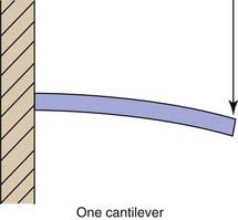
Any understanding of FRC bridges must begin with beam theory. A beam is defined as a structural member that is subjected to loads applied transverse to the long axis. The simplest type of beam is known as a cantilever (Figure 12-1). This concept, familiar to most dentists, refers to a beam supported and retained at one end, called encastré by engineers. Near the middle of any beam is a line (or a plane in three dimensions) known as the neutral axis. This axis coincides with the centroid or geometric center of the beam. The longitudinal stresses along this line are zero. The stresses in a cantilever beam are essentially tensile above this line and compressive below it. The farther from the neutral axis, the greater the stress. This explains the success of I-bar beams, as the greatest strength of the beam structure is concentrated farthest from the neutral axis, where there is the greatest stress.

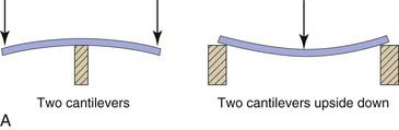
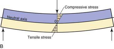
The second type of beam is a simply supported beam. This type corresponds to a board laid across a puddle. A simply supported beam is essentially two cantilevers turned back to back and upside down (Figure 12-2, A). The stresses on it are compressive above the neutral axis and tensile below it (Figure 12-2, B).

The third type of beam is a combination of the cantilever and the simply supported beam. This beam is supported at both ends, but both ends are retained or encastré. This is the type of beam being constructed when a dental bridge is being fabricated. It has structural elements of both types of beam. Tensile stresses are below the neutral axis, but above the neutral axis there are compressive stresses in the beam’s middle and tensile stresses toward the ends. Cutting this type of beam in the center produces two cantilevers end to end. If we release the hold on the ends, we have a simply supported beam. This may partly explain the discrepancy between the failure of FRC in the literature and its success in practice. Although it is clear that any in vitro testing requires that the material be supported at both ends to simulate what occurs when we fabricate a fixed partial denture, most studies do not specify how the material is retained for testing.

The Science of Fiber-Reinforced Composites

To understand FRC bridges, it is also important to examine the mechanism of failure of composite materials. Although a detailed discussion of fracture mechanics is beyond the scope of this book, there are factors that help to explain the discrepancy between clinical successes and laboratory failures.

Materials can be described as brittle or ductile. When the elastic limit of a material is exceeded, brittle materials fracture and ductile materials bend. Dental composites bend very little and are classified as brittle, even when the composite is reinforced with fibers.

Dental composites, like all brittle materials, fail as a result of crack propagation. Geometric defects within the structure act as points of stress concentration. These irregularities can be holes, bubbles, cracks, sharp corners, and so on. These faults cause the stresses within the material to become focused at these points, causing the initiation of fracture, even though the overall stress within the material is well within its theoretical strength. This is the same principle used in cutting glass. A small scratch is etched on the glass surface, and a stress is applied to the material. The scratch acts as a source of stress concentration, and the glass fractures cleanly along the line scratched in its surface. If the scratch does not continue completely across the sample, the fracture still begins where the scratch concentrates the stress and propagates irregularly across the glass, because the end of the fracture becomes the new point of stress concentration, until failure occurs. Clinical success or failure of FRC may be as much a function of our success in minimizing the microcracks and irregularities in the structure as of the inherent strength of the materials.

The fracture resistance of any material is less a function of its strength than of its toughness. Fracture toughness is the resistance of a material to form cracks and is a measure of the damage tolerance of the structure. Glass and steel have similar tensile strengths, but no one would suggest the two are interchangeable; steel is tougher than glass. One small crack in a pane of glass results in rapid propagation of the crack, resulting in fracture of the glass. Small cracks in steel do not necessarily produce fracture. When the structure is placed under stress, thousands of microcracks are created within the material. These microcracks tend to travel through the structure and, if they are permitted to connect with one another, eventually coalesce into macroscopic cracks, then fracture lines.

The fibers within FRC enhance the load-bearing capacity of the structure by two separate and distinct mechanisms. First, the fibers act as a stress-bearing component, as would be intuitively expected. They support the forces of occlusion much like cables in a suspension bridge. They also strengthen the composite by acting as a crack-stopping and crack-deflecting component. As microcracks propagate through the resin matrix, if they encounter a fiber, they are stopped and deflected along the interface between the fiber and resin. The fiber becomes circumferentially detached from the resin matrix. When the crack intercepts another fiber, it forks and divides, multiplying the number of cracks in the structure. The creation of each new crack consumes energy and increases the work of fracture for the material. This mechanism dissipates the energy applied to the structure. The process of branching of cracks continues until energy demands become too high or the material fractures. Over time, the accumulation of cracks within the structure begins to act as a stress relief mechanism. Stresses are relieved by the friction between the material surfaces in contact at the crack. Flexure of the prosthesis also transfers stresses to the fibers, which then support the structure as a stress-bearing component.

Which of these two mechanisms is more important is open to some debate. Rudo and Karbhari argue in their article “Physical Behaviors of Fiber Reinforcement as Applied to Tooth Stabilization” that woven material is superior to unidirectional material in vivo. Whereas unidirectional material exhibits superior strength in the direction of the fibers, there is little correlation between the stresses placed on a dental restoration and the unidirectional stresses placed on the materials in laboratory testing. Rudo and Karbhari argue that the load-bearing action of the fibers is secondary to their crack-stopping function. Therefore the fibers need not be unidirectional. Woven fibers may offer greater strength, because the intersecting fibers are more effective at stopping and deflecting cracks.

Regardless of the mechanism, the incorporation of reinforcing fibers into dental composite increases the material’s strength. The tensile (and therefore the flexural) strength of the resulting structure is enhanced by the fibers. The more fibers that can be incorporated, the greater the strength achieved. The principle is well stated in the rule of mixtures, which states that the mechanical properties of a composite material are proportional to the volume and properties of the individual components in the mix. In reality, the strength of FRC dental restorations tends to be less than theory would suggest, mainly because the limitations imposed by the space and design considerations of a dental restoration reduce the amount of fiber that can be incorporated into the structure. The literature tells us that the amount of fiber incorporated into most dental structures is low, usually on the order of 15% by volume.

Material Options

FRCs have been used with great success in industrial applications for many years. The most common and best known of these materials is fiberglass, the generic term for various forms of plastic reinforced with glass fibers. (Fiberglas [with one s] is a registered trademark belonging to Owens-Corning [Toledo, Ohio] for their glass fibers, which are used both in composite materials and as insulation.) These materials are used in the manufacture of myriad products, including boat hulls, automobile bodies, aircraft propellers, and windmill blades. The enormous popularity of high-performance homebuilt aircraft was made possible in large part by the availability and reliability of FRCs. Available materials include epoxy and polyester resins reinforced with fibers such as glass, aramid, graphite, and ceramic. In addition, these fibers are available in various configurations, including unidirectional, bidirectional, woven, and braided.

Commercially Available Fiber Systems

All fiber reinforcement products are variations on two major systems: plastic or glass. Plastic fibers generally have handling characteristics superior to those of glass, whereas glass is generally the stronger material.

Most plastic fiber systems are polyethylene. The fibers are usually braided or woven into a ribbon, with each manufacturer claiming to have the superior configuration. In reality, how fibers are woven makes little difference in the strength of the resulting restoration. It can, however, result in differences in how the material handles. Concerns also arise about the ability to fully impregnate certain tightly woven configurations of fibers with resin.

The surface of plastic fibers is usually treated with cold gas plasma to enhance the bond between fibers and resin. In this technique the fibers are exposed to a partially ionized oxygen gas that acts through a process of ablation and activation. The ablation results in an etching of the fiber and an increase in the presence of chemically active groups on the fiber surface. These groups chemically bond to the resin, while the etched surface facilitates a micromechanical bond. The plasma treatment also enhances the wettability of the fiber surface, which increases the resin in contact with the fiber and helps to reduce the presence of voids and bubbles at the resin-fiber interface, which act as points of stress concentration. Cold gas plasma treatment is highly susceptible to contamination, however. The fibers therefore must be handled carefully to prevent contamination before they are impregnated with resin. One manufacturer includes a pair of cotton gloves in the kit to protect the fibers during handling, but these are not practical. Carefully avoiding touching the fibers before impregnating them is adequate.

Glass fibers are of two types, E-glass or S-glass. The two materials are different chemically, but handling is essentially identical. S-glass is the stronger of the two and has a higher modulus of elasticity. Glass fibers are stronger in theory than plastic, but their stiffness makes them much more difficult to work with clinically. S-glass fibers are stiffer, so elastic memory is more problematic in handling and placement for dental applications.

Glass fibers are etched and silanated to enhance the resin-to-fiber bond. The etching process is similar to etching porcelain before bonding, although the actual process is proprietary. Etching glass fibers is, by all reports, duration and chemistry critical. Glass fibers cannot be etched and silanated chairside. If they are over-etched, their strength diminishes dramatically; if they are under-etched, the bond to resin is inadequate.

Treatment Considerations

The introduction of FRC represented the first opportunity for composite bridge fabrication that could be considered successful. Numerous authors have described techniques meeting with varying degrees of success. The techniques may be indirect or direct.

Indirect Methods

Several manufacturers have developed FRC materials for laboratory-fabricated prostheses, with mixed success. One advantage of the indirect technique is that it uses techniques and procedures reasonably familiar to most dentists. The concepts of preparing the teeth, making an impression, and fabricating a provisional restoration differ little from making a porcelain-fused-to-metal bridge. The procedure for bonding the prosthesis is the only departure from more traditional techniques.

Another advantage to the indirect technique is that it is possible to cure the composite using heat and pressure to enhance the strength and wear resistance of the cured composite. Unfortunately, this also results in the greatest shortcoming of indirect composite techniques. When a composite restoration is fabricated in a laboratory, especially when it is cured with heat and pressure, it must be bonded using almost entirely micromechanical means, because the polymerization of the composite will have progressed to the point that there will be few free radicals left for chemical bonding to the composite resin. The composite’s surface may also become corrupted by myriad contaminants during the fabrication process, including the surface of the stone cast. These contaminants must then be removed. Whatever technique is employed to clean and etch the surface before bonding will remove any air-inhibited layer, eliminating any chance for chemical bonding. Thus there is an obvious advantage to fabricating the entire prosthesis in place in the mouth.

Direct Methods

In 1981, Belvedere placed some of the first directly bonded FRC resin bridges using Kevlar fibers. The first bridge was a four-unit prosthesis replacing two maxillary central incisors using the laterals as abutments in a 22-year-old woman. At last report (1989) the bridge was still in service and had not been repaired or replaced. Nearly 400 bridges have been reported to be in service, with a 98% survival rate over an 8-year period.

In 1994 Abel described a technique for the direct fabrication of an FRC bridge to replace incisor teeth. The technique was a bold attempt but failed to deal with several important issues. Significant in any bridge design is the tissue contact surface of the pontic, and Abel’s technique fails to address this. The article is unclear, but it appears that he simply fabricated the pontic in place, in direct contact with the tissue, and allowed the gingiva of the edentulous space to develop the tissue surface form of the pontic.

Culy and Tyas described a technique for direct fabrication of FRC anterior bridges. They replaced 26 single upper anterior teeth and one premolar using hybrid composite reinforced with plasma etched polyalkane fibers (Fibrespan, Nulite Systems, Sydney, Australia). They followed their cases for only 10 months, and two bridges failed as a result of trauma. Of the 27 bridges, 25 were of cantilever design, which the authors argue is more predictable because there is no differential movement between the abutments. This runs counter to conventional wisdom regarding bridge design. The authors also found the process to be “technically demanding,” particularly with respect to the pontic saddle design, but offered the technique as a viable option for conservative tooth replacement.

In 1998 Belvedere described how to fabricate a direct FRC bridge to replace missing central or lateral incisors. His technique addresses the problem of controlling the tissue surface of the pontic with the fabrication of a “pontic button.” The portion of the pontic in contact with the tissue is fabricated in place in the mouth and trimmed, and the tissue surface is contoured and polished before being incorporated into the restoration. The abutment teeth are prepared and bonded, the fibers are placed, and the pontic button is positioned under the fibers. The coronal portion of the pontic is then custom fabricated in place in the mouth. The technique is a marked improvement over previous attempts but requires significant clinical skill to manipulate all the parts and materials successfully into position.

Although many of the problems associated with the direct fabrication of FRC resin bridges have been solved, the clinical techniques for bridge fabrication still need refinement. Belvedere’s technique addresses the problem of controlling the tissue surface of the pontic. Unfortunately the technique is so technically demanding that few clinicians are willing to attempt it on a regular basis.

Technical Considerations for Direct Bridge Fabrication

Several issues must be considered when fabricating FRC bridges directly in the mouth. Voids and bubbles act as points of stress concentration within the structure, so it is worthwhile to minimize the bubbles trapped within the mix. The greatest problem in accomplishing this is adequately wetting the fibers. Fibers require wetting with an unfilled resin; filled or flowable materials have higher viscosity and do not wet the fibers as effectively, permitting bubbles and voids to become entrapped on the fiber surface. Once the fibers have been wetted with unfilled resin, they can be further wetted with a flowable composite before they are introduced to the more highly filled composite. Although intuitively this seems to represent the greatest potential for getting filled composite in intimate contact with the reinforcing fibers, at the time of this writing this has not been supported or disproved by research.

In deciding on the placement of the fibers within the restoration, beam theory can supply guidance. In a three-unit bridge supported at both ends, the tensile stresses are concentrated below the neutral axis of the beam. In a bridge that is encastré (retained) at both ends, as in a fixed partial denture, tensile stresses are also located above the neutral axis toward the ends of the bridge. In a cantilever beam (or a cantilever bridge), tensile stresses are located above the neutral axis of the beam. Beam theory teaches that the stress on a beam increases as the square of the distance from the neutral axis to the tensile side. Fibers should be located where they will absorb the tensile stresses within the structure, so when a cantilever bridge is being constructed, the fibers must be concentrated toward the occlusal or incisal part of the restoration. In fabricating a three-unit fixed prosthesis, fibers should be concentrated below the neutral axis—that is, toward the gingival portion of the bridge. In practical terms, it is desirable to incorporate as much fiber into the structure as possible. The limitations of fabricating a dental prosthesis, especially directly in the mouth, are such that we can seldom incorporate as much fiber as desired. The risk of using too much does not exist from a structural standpoint but can be a problem in that it must be completely covered with composite resin.

Unfortunately, the forces applied to a dental prosthesis are not as simple as they are when building a floor. Among the complex forces seen in clinical applications of fiber-reinforced technology is the phenomenon of torquing of posterior bridge pontics. When occlusal loads are applied to a posterior bridge pontic, they are not necessarily applied to the center of the pontic or beam. Off-center loading results in a torsional force, or twisting of the pontic or beam. These torsional forces are best resisted by fabricating a pontic or beam with long unidirectional fibers that are spiral wrapped with unidirectional fibers. This can be accomplished in the fabrication of indirect prostheses and is included in several of the commercially available systems used for laboratory fabrication. Unfortunately, spiral wrapping of the reinforcing fibers is an engineering principle that is difficult to achieve when fabricating the restoration directly in the mouth. For direct posterior bridge fabrication in the mouth, one must keep the bucco-lingual width of the pontic to a minimum and design the anatomy to eliminate working and balancing contacts. This reduces the potential for off-center loading of the pontic and the resulting torsional stresses on the bridge.

Clinical Conservation Concepts with Fiber-Reinforced Composite Bridges

The concept of preserving tooth structure is hardly new to dentistry. Partial veneer crown retainers, pinledge retainers, and the MacBoyle retainer were all attempts to preserve as much valuable tooth structure as possible, although the motivation behind this may have been more the inability to imitate enamel with then available materials. Today’s restorative materials are so predictable and esthetic that preserving tooth enamel may not seem as essential as in the past, but it is still an important consideration in dentistry.

With the development of acid etch bonding by Dr. Michael Buonocore in the mid-1950s, the potential for conservative, esthetic tooth replacement increased dramatically. In the late 1970s the Maryland and Rochette bridge designs were developed as conservative methods of anterior tooth replacement. These were the first to find their way into routine use in dentistry. Ironically, both proved to be more effective as posterior bridge techniques, largely because the bond between tooth and metal was not adequate to retain the bridge without supplementation by mechanical retention. Both techniques continue in use as conservative alternatives to fixed prosthetics with full coverage retainers. With proper case selection and careful implementation they provide predictable and conservative restoration. Their disadvantages include a tendency of the retainer color to be transmitted through the abutment teeth causing a gray discoloration, and frequent debonding from the abutment teeth.

Other attempts to develop conservative techniques for tooth replacement include the technique described by McIntyre for replacing maxillary first bicuspids and lateral incisors using a bridge design with a conventional full-coverage retainer on one end and a small metal extension on the other end that is embedded in composite in a conservative class III preparation. A similar technique for replacing posterior teeth was described by El-Mowafy. In this technique a bridge is fabricated with cast projections on both ends. These projections are embedded in composite in conservative preparations in the abutment teeth.

In the late 1970s, Belvedere used fine wire mesh to reinforce bonded composite bridges, but these were not particularly successful. With no bond between the metal mesh and the composite, the metal did little to reinforce the structure and may have weakened it by acting as a focus of stress concentration.

Before fiber-reinforced technology was developed, attempts were made to bond acrylic denture teeth directly to natural teeth. Ibsen first described a technique for using unreinforced composite to bond acrylic denture teeth to natural teeth in 1973. In 1978 Jenkins reported on 31 bridges placed in 22 patients using acrylic teeth bonded in place with composite resin. The technique was spectacularly unsuccessful, with a slightly better than 50% survival rate at 3 years. The mode of failure of the restorations was consistently fracture of the composite. He found the success rate for lower prostheses to be encouraging, however. A likely explanation for the discrepancy between the upper and lower restorations is the fact that the uppers are subjected to a greater proportion of tensile loading, whereas the lowers are subjected to more compressive loads, which particulate composite is better suited to resist.

In 1980 Jordan and colleagues reported on 88 bridges in 78 patients fabricated using acrylic denture teeth bonded in place with composite resin, with pins used in the abutment teeth for additional retention in some cases. The results were disappointing, the majority being lost within a year. The researchers observed that when failure occurred, it was invariably fracture of the composite, and concluded that the limiting factor in the technique was the strength of the composites available. They also concluded that the most predictable application of the technique is the replacement of a single mandibular incisor.

Simonsen hypothesized that the weak link in the acrylic denture tooth bridge was the bond between the acrylic tooth and composite resin. He further reasoned that if the pontic were made from composite, the bridge would be stronger. In his technique the pontic was fabricated from composite resin using a clear plastic crown form. The pontic was then bonded into place with the same technique as for acrylic denture teeth. The survival rate for prostheses fabricated with a composite pontic was an improvement over the acrylic denture tooth technique.

Clinical Techniques

Anterior Bridge Technique

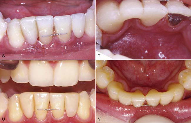
The technique for direct intra-oral fabrication of an anterior FRC bridge begins with a set of study models. The model is modified with wax or composite to create the lingual contours desired of the completed bridge (Figure 12-3, A). The author typically uses composite to mock up the lingual portion of the pontic and then flows inlay wax onto the lingual surface of the abutment teeth on the models to simulate the thickness of the retainer and the fibers on these teeth. The labial surface of the pontic is of no concern at this stage; it will be developed in the mouth when the bridge is fabricated.

image image image image

FIGURE 12-3 A, The lingual contours of the bridge are mocked up in composite or wax on a study model. B, The matrix is fabricated from vinyl polysiloxane putty. If teeth are dark or opaque, transparent material can be used to permit polymerization through the matrix. C, The matrix is inserted in the mouth to ensure good fit. It will be used as a mold to form the lingual and gingival surfaces of the pontic button. Marks on the matrix are made to simplify placement of the matrix in the mouth. D, Composite is injected into the space created by the matrix, tissues, and abutment teeth to create the basic form of the pontic button. E, The pontic button is trimmed to establish an outline form and tissue surface contours. F, Once the appropriate contours are established, the tissue surface and lingual surface of the pontic button are polished to a high shine. G, A chamfer finishing line is created around the outline of the labial surface to establish a well-defined line to finish the composite to when developing the rest of the pontic. At this time the pontic is also contoured to ensure adequate room for the fibers to pass between the pontic button and the abutment teeth. H, The completed pontic button should be reasonably stable when placed back on the matrix. I, When the fibers and the pontic button are ready, the teeth are prepared by roughening the enamel and preparing conservative class III preparations on the abutments. The teeth are then etched and a dentin adhesive applied. J, Dental tape or floss is positioned and cut to length to serve as a pattern for the fibers. K, The dental tape pattern is used to measure the length of the fibers required. The fibers are cut to length and placed on a piece of tin foil, which will be used to protect the wetted fibers from ambient light while the teeth are prepared for bonding. A light-resistant container can also be used. L, The fibers are wetted with unfilled resin and then impregnated with light body composite resin. M, The tin foil is folded over to protect the impregnated fibers from ambient light and set aside. N, As the assistant ensures the teeth remain dry and uncontaminated, the dentist places the pontic button on the matrix and a small amount of low-viscosity composite on the abutment area of the matrix. O and P, Composite is then applied to the abutment areas of the matrix. The impregnated fibers are recovered from the tin foil and placed in position on the matrix. Q, All parts of the anterior direct fiber-reinforced composite bridge are shown in place on the matrix and ready for insertion in the mouth. R, After curing with the matrix in place, the lingual surface of the bridge is essentially complete. Only minor trimming and polishing are required. S and T, The lingual surface of the completed bridge demonstrates a modified ridge lap pontic design to facilitate hygiene. U and V, This 8-year follow-up of the case demonstrates that direct fiber-reinforced bridges no longer need to be considered purely provisional or temporary restorations.

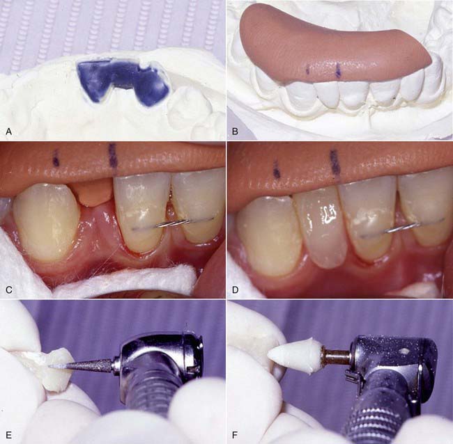
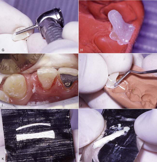
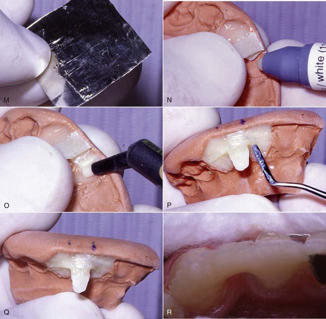
A matrix is then fabricated using clear polyvinyl impression or bite registration material. This material is mixed according to the manufacturer’s instructions and applied to the lingual surface of the model to register the contours developed in the mock-up (Figure 12-3, B). Opaque matrix material can be used as shown in Figure 12-3, B, but transparent materials allow for the structure to be polymerized through the matrix after the initial trans-enamel polymerization, which ensures all the composite will fully gel before the matrix is removed.

It has been argued that the need to do a mock-up on the study model negates its advantage of being completed in one visit. This is rarely a problem, as study models are such a routine part of the diagnostic procedure before fabrication of any bridge. Because the entire bridge fabrication procedure takes the average dentist about 2 hours, it is unlikely that the procedure will be performed on a patient who has never been seen before.

At the fabrication appointment the abutment teeth a/>

Stay updated, free dental videos. Join our Telegram channel

Jan 3, 2015 | Posted by in Esthetic Dentristry | Comments Off on 12: Fiber Reinforcement

VIDEdental - Online dental courses

Get VIDEdental app for watching clinical videos