Chapter 12
Bone Expansion
Introduction
Maxillary bone expansion allows a narrow maxillary ridge to be widened for the simultaneous insertion of implants. Specific criteria that need to be assessed are:
- • relationship of residual ridge to planned tooth position
- • bone width and ridge morphology
- • height of available bone.
A summary of the assessment is shown in Flowchart 12-1. This procedure may be carried out in situations where there is insufficient width of bone for an implant to be inserted (Fig 12-1). Conventional osteotomy would lead to a dehiscent implant, which would be compromised. The loss of bone takes place at the expense of the labial plate, and consequently the procedure is designed to manipulate the labial plate in attempt to reconstruct the ridge.204–206
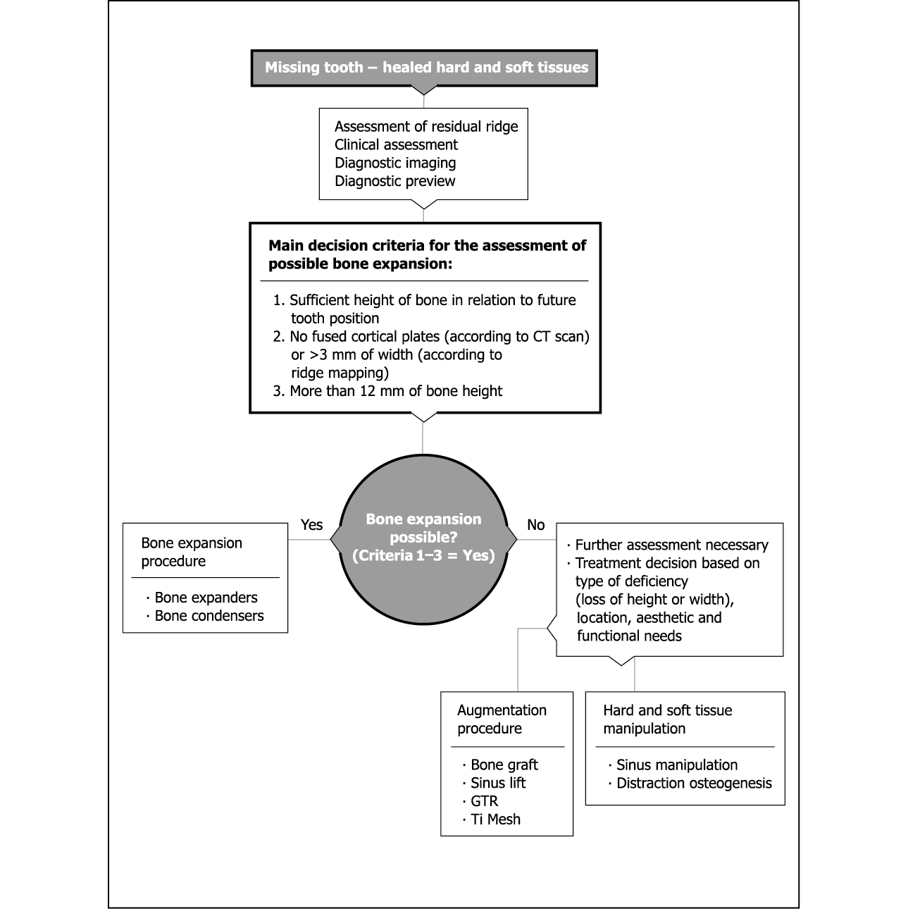
Flowchart 12-1 Assessment for bone expansion.
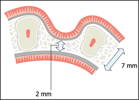
Fig 12-1 Diagram of a severely resorbed maxillary ridge requiring expansion. Two separate cortical plates with intervening cancellous bone are considered to be a requirement for maxillary bone expansion. Note the severe loss of ridge width at the expense of the labial plate, which is typical of patients with prominent roots with large interdental depressions.
It is clear that the implant must be placed between the cortical plates. The angle at which the implant is placed is, therefore, dictated by the orientation of the residual ridge. This often differs from the longitudinal axis of the tooth that needs to be restored (Figs 12-2 and 12-3). A wide range of angled abutments should be available so that the implant can be restored without compromising the aesthetic outcome.204 This procedure may also be used to re-contour the labial plate where sufficient bone is present but is not in a position suitable for producing ideal aesthetics because of the collapse of the labial plate (Figs 12-4 and 12-5). This would otherwise result in an implant being placed too far towards the palate, leading to poor aesthetics or to the ridge lapping of the crown.
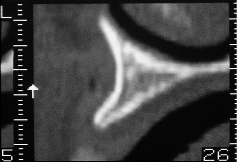
Fig 12-2 Oblique cross-sectional CT image showing a narrow maxillary ridge, which widens rapidly. The angulation of the maxillary ridge should be noted as it will influence the position of the implant and its relationship to the restoration.
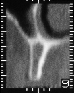
Fig 12-3 Cross-sectional CT image of the maxillary ridge in the premolar region showing a narrow ridge with thin cortical plates and cancellous bone of low density. Note the angulation of the ridge in comparison with the previous image (Fig 12-2).
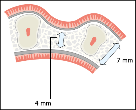
Fig 12-4 Axial cross-section of a typical ridge following tooth loss and collapse of the labial plate. Typically such a ridge may result in the labio-coronal part of the implant being dehiscent or the implant being positioned too far palatally.
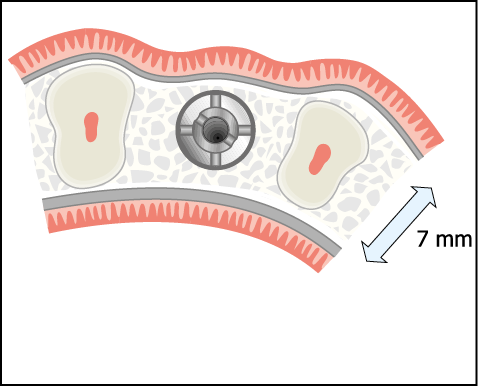
Fig 12-5 The re-contouring of the labial plate, using bone condensers or bone spreaders to ensure that the correct emergence profile as well as the correct position of the implant can be achieved.
Tatum originally developed the technique for the insertion of ‘D’-shaped finned transmucosal implants.206 The technique has evolved and the version described here has been modified for the insertion of screw-form two-stage submergible implants that are allowed to integrate in a closed environment.204,205 Other techniques with varying success rates have been described in the literature.207–212
Height of the Crestal Ridge
The technique described here is designed to increase the width of the ridge and cannot be used to increase ridge height. The crestal ridge height needs to be assessed, taking into account the level of the bony ridge and the level of the soft tissues.
The level of the soft tissue can be assessed visually and should ideally be the same as the papillae of the adjacent teeth. This is particularly important for multiple implants, where it is difficult to create natural contours when the implants have been placed adjacent to each other. This assessment can be facilitated by reference to the diagnostic preview and the provisional restoration made from it. The diagnostic preview has to be used judiciously, projecting an increase in width of approximately 2 mm. For multiple units, an assessment of the lip support should also be made.
Periapical radiographs give a good indication of ridge height for single-tooth implants or short spans. The level of bone attachment to the adjacent teeth should be noted, as well as the midcrestal level.
CT scans should have reference radiopaque markings so that tooth position can be assessed in relation to the future implant position.
Bone Width and Ridge Morphology
In order to undertake ridge expansion, the ridge must constitute two separate cortical plates with intervening cancellous bone. This can best be assessed by means of a CT scan or conventional tomograph, which will provide information regarding the width of the ridge, the thickness of the cortical plate, the density of cancellous bone between the cortices and the angulation of the ridge (Figs 12-2, 12-3 and 12-6). Where a CT scan is not possible, ridge mapping should be carried out to provide details of the width of the bony ridge. Several points starting at 3 mm from the crest of the ridge and moving towards the base of the ridge should be measured. This will indicate whether the ridge narrows or widens towards the base. If a minimum ridge width of 3 mm can be found, separate cortical plates with intervening cancellous bone, suitable for ridge expansion, are likely to be present. Although a 2 mm ridge can also be expanded, the likelihood of fused cortical plates is higher and a CT scan is desirable prior to proceeding.
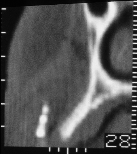
Fig 12-6 Fused cortical places of a maxillary ridge, which would not be considered suitable for maxillary bone expansion.
Height of Available Bone
The ridge should be a minimum of 12 mm in height to ensure adequate primary stability and sufficient bone support. If the height of the ridge is marginally less than 11 mm, sinus or nasal floor manipulation may be carried out in combination with the expansion procedure.
Treatment Sequence
Bone expansion should be carried out in a healed site with matured cortical plates. A healing period of three to six months after implant insertion is recommended to ensure that integration takes place. Immediate loading is not generally recommended because of the fragility of the labial plate, which has just been repositioned, and because primary stability may well have been compromised. It is for this reason that this protocol has been developed for submergible implants (two stage) in order to minimise trauma from occlusal forces during healing. An exception to this may be where minimal re-contouring of the labial plate has been undertaken and sufficient primary stability has been achieved to enable early or immediate loading, as determined by the criteria described above. The use of a two-stage implantation procedure with the implant being submerged at first-stage surgery to allow integration has additional benefits. These relate to the ability to develop the desired emergence profile by manipulating the soft tissue at the time of implant exposure.
Surgical Protocol
Flowchart 12-2 summarises the sequence of instruments needed for either bone expansion or labial re-contouring.
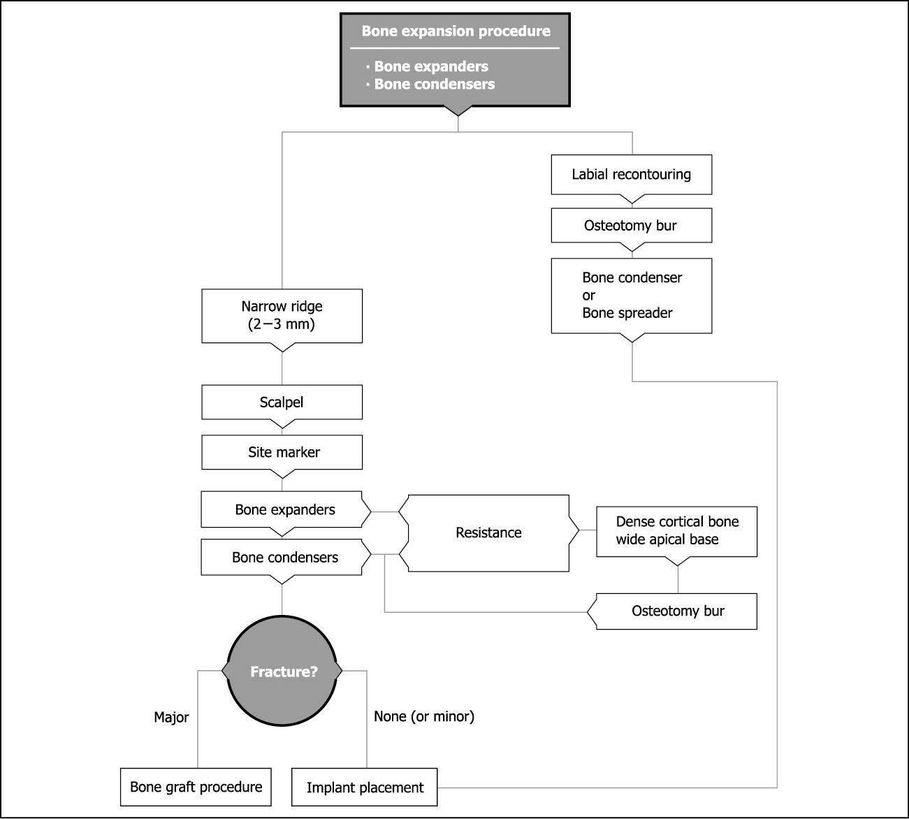
Flowchart 12-2 Bone expansion and labial recontouring.
Remote Palatal Incision
Access to the ridge is gained via a remote palatal incision made approximately 1 cm from the crest of the ridge. The perpendicular component of the incision is made with a number 15 blade in a conventional handle. The palatal incision is made with a Blake’s knife (blade number 15) and is bevelled towards the crest to allow for closure of the wound after expansion (Fig 12-7). The buccally based flap is elevated using a curved elevator (Dentsply Friadent) to expose the crest of the ridge. To ensure that the blood supply to the labial cortical plate, which is supplied by the periosteum, is not interrupted, the labial periosteum is not reflected.213
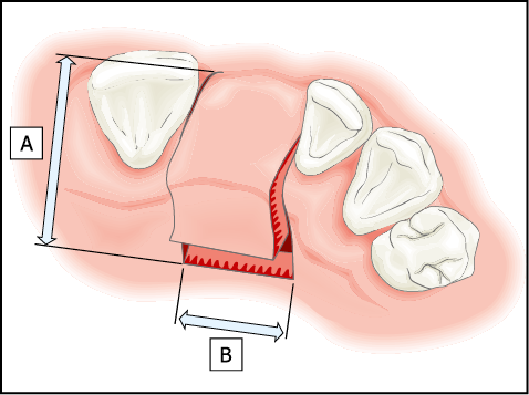
Fig 12-7 The outline of the remote palatal incision for the exposure of a healed maxillary ridge in the region of an incisor. The incision consists of two components. First, two incisions are extended into the palate to a distance of approximately 10 mm each (A). These incisions are designed to include the papilla and to extend within the gingival sulcus towards labial aspect. The second component (B) is a bevelled incision made parallel to the ridge joining the incisions. A Blake’s knife is the most suitable instrument for this. This produces a full-thickness flap with a bevelled component, which is buccally based. The labial periosteum is not elevated to ensure that an adequate blood supply is maintained to the labial cortical plate, which will be manipulated during the procedure of maxillary bone expansion.
The rationale behind a remote palatal incision is that it enables closure of the wound in a predictable manner after expansion. In addition, this is the appropriate incision for a bone graft should that be required in the event of a fracture of the labial plate.
Instrument Sequence
Ridge expansion is a surgical art form in which a specific protocol should be followed in order to attain a successful and predictable expansion. A sequence of instrument use has been developed, which is outlined below. Use of this specific sequence coupled with appropriate surgical skills results in a high success rate.204 The skills required for the use of the protocol outlined below should be obtained before attempting treatment on severely resorbed ridges. There are several animal models that may be used to become familiar with the behaviour of bone and mode of employment of the instruments. It is advisable that the clinician be familiar with the use of instruments, such as bone expanders and bone condensers, for the preparation of osteotomies in maxillary bone.
Scalpel
The scalpel is used with good finger support to score the crest of the ridge, defining the plane of expansion (Fig 12-8). It should be possible to visualise the labial displacement of the buccal plate at this point. Accurate marking of the ridge is very important (Fig 12-9).
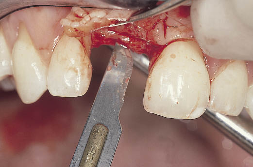
Fig 12-8 The ridge is exposed via a remote palatal incision and a scalpel is used to define the plane along which the bone expansion is to be carried out.
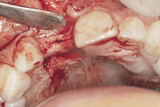
Fig 12-9 Occlusal view of the ridge, which has been marked using a scalpel and a position marker. Note the width of the ridge (2 mm at the crest) in comparison with the width of the adjacent teeth (7 mm).
Position Marker
The position marker (site marker) is used to select the implant site (Fig 12-10). It is introduced into the ridge to identify the direction of the proposed osteotomy. The position marker is aligned between the labial and palatal cortical plates parallel to adjacent teeth or adjacent implant. The position marker is inserted to a depth of about 10 mm, but this will depend on the amount of bone available. The position marker directs itself between the cortical plates along the line of least resistance, ensuring that there is no perforation.
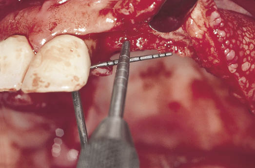
Fig 12-10 Intraoperative image of the left maxillary ridge showing the selection of sites. The lateral incisor is positioned 4 mm from the central incisor and the canine is positioned 7 mm from the lateral incisor to provide adequate interdental spacing. The position marker can be seen marking the implant site as well as establishing the direction of the osteotomy between the cortical plates.
For a single implant, the site should be selected in the middle of the ridge, taking the local anatomical structures (such as incisive canal) into account. The site can be selected visually with sufficient accuracy.
For multiple implants, a minimum distance of 7 mm from the centre of each implant site is necessary for 3.5-mm implants in order to sustain an adequate interimplant bone height. A surgical template may be useful in selecting implant sites to coincide with tooth positions.
Bone Expanders (Ridge Expanders)
Bone expanders are used to separate the cortical plates (Figs 12-11 and 12-12). The principle behind the use of these instruments is to facilitate bone expansion over a larger area without the formation of sharp angles, thus minimising the risk of fracture (Figs 12-13 to 12-16). During the course of the expansion procedures, the labial and palatal cortical plates are supported firmly to prevent fracture. Particular attention should be paid to supporting the palatal bone. Loss of the palatal bone in the event of a fracture results in a loss of height, which is more difficult to rectify.
Stay updated, free dental videos. Join our Telegram channel
VIDEdental - Online dental courses


