Chapter 11
Computed Tomography (CT)-Guided Surgery/Immediate Occlusal Loading with a Full-Arch Prosthesis in the Edentulous Mandible
LITERATURE REVIEW
Immediate Occlusal Loading
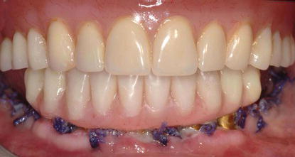
Immediate occlusal loading (IOL) was defined by Testori et al. (2003) as placing at least five implants into edentulous mandibles, splinting them together with a rigid fixed prosthesis, and placing them into full functional occlusion on the day of implant placement. Their preliminary study reported the results of 15 patients, with 103 implants that were placed into function within 36 hours of implant placement. Patients were followed for up to 48 months postoperatively; Testori and others reported an implant cumulative survival rate (CSR) of 98.9% and 100% CSR for the immediate prostheses. Testori and others concluded that rehabilitation of edentulous mandibles with immediately loaded hybrid prostheses, supported by five to six implants, may represent a viable alternative treatment to the classic delayed loading protocols (Figures 11.1–11.3).
Romanos et al. (2013) more recently reported on patients treated with IOL for 6+ years. After a mean loading period of 75.29 (± 38.18) months, they reported that no implants were lost (100% success rate). They also reported that all clinical indices had values in normal levels. Crestal bone levels were relatively stable and only minimal crestal bone loss was observed in some implants. Romanos and others concluded that patients restored with this protocol exhibited long-term success and stability of the peri-implant tissues around immediately loaded mandibular implants.
Figure 11.1 Preoperative panoramic radiograph of a patient to be treated with extractions of the remaining mandibular teeth, alveolectomy, immediate placement of five interforaminal mandibular implants, and fabrication/insertion of an immediate fixed, mandibular implant-retained prosthesis with full occlusal loading on the day of surgery.
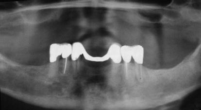
Figure 11.2 Postoperative panoramic radiograph of the patient in Figure 11.1 immediately post implant placement and abutment connection.
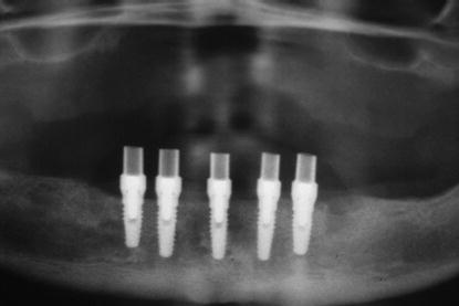
Figure 11.3 Postoperative clinical image of the patient in Figures 11.1 and 11.2 prior to discharge after the preceding surgical and prosthetic treatments were accomplished.
Tilted Implants
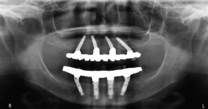
Capelli et al. (2007) reported on the results of a study that assessed treatment outcomes of immediately loaded full- arch screw-retained prostheses with distal extensions sup ported by both upright and tilted implants for the rehabilitation of edentulous jaws; the study also compared the outcomes of upright versus tilted implants. At 4 study centers, 342 implants (OSSEOTITE NT ® , Biomet 3i™, Palm Beach Gardens, FL, USA) were consecutively placed into 65 patients (96 implants/24 mandibles, 246 implants/41 maxillae). The two distal implants in all jaws were tilted 25°–35°. Provisional full-arch restorations (titanium frameworks and acrylic resin teeth) were delivered within 48 hours of surgery and immediately loaded with full functional occlusion. Definitive prostheses were delivered 3 months postimplant and prosthesis placement (Figure 11.4).
Capelli et al. (2007) reported that three implants failed during the first year; an additional two implants failed within 18 months of loading in the edentulous maxillae. The CSR for the maxillary implants was 97.59%, with up to 40 months of follow-up. No implant failures were recorded for the mandible. The prosthetic survival rate (SR) was 100%. Marginal bone loss around upright and tilted implants was similar. Patients reported that they were satisfied with their aesthetics, phonetics, and function. Capelli and others concluded that the preliminary results suggested that IOL of edentulous maxillae and mandibles with hybrid prostheses supported by six or four implants, respectively, may represent a viable treatment alternative for treating edentulous patients without significantly more invasive surgeries such as sinus lifts or block bone grafts. The clinical results indicated that immediately loaded tilted implants may achieve the same outcome as upright implants in both jaws. Other researchers have reported similar high CSRs for IOL in both edentulous jaws (Bergkvist et al. 2005; Maló et al. 2005; Tealdo et al. 2008; Cavalli et al. 2012; Ostman et al. 2012).
Figure 11.4 Postoperative panoramic radiograph of a patient treated with maxillary and mandibular tilted posterior and vertical anterior implants; the implants were immediately loaded with full-arch restorations.
Patzelt et al. (2013) reported the results of a systematic review. They evaluated the All-on-4 (AO4) treatment concept with regard to SRs of implants, definitive prostheses, and crestal bone levels. They identified 13 papers out of 487 that were initially identified in the search. The papers reported on the results of 4804 implants; 74 of the implants failed; 74% of the failed implants occurred within the first 12 months. A total of 1201 prostheses were inserted within 48 hours of the surgery. They reported that the major prosthetic complication involved fracture of the acrylic resin interim prostheses. The mean SRs were 99.0% and 99.9% for implants and prostheses, respectively. Average crestal bone loss was reported at 1.3 mm. No statistically significant differences were found in outcome measures comparing maxillary versus mandibular arches and axial versus tilted placed implants. Patzelt and others concluded that the available data provided promising short-term results for the AO4 treatment approach. However, they also concluded that current evidence was limited by the quality of available studies and the scarcity of long-term data for clinical outcomes of 5 years or greater. The authors recommend further studies be designed as randomized controlled clinical trials and reported for publication.
Diagnostic Imaging
Diagnostic imaging plays a significant role in developing comprehensive diagnoses and treatment plans. Per Kircos and Misch (2005), the decision when to image and which imaging modalities to use may be organized into three phases:
Phase I has been identified as preprosthetic implant imaging; this includes all necessary surgical and prosthetic information to determine quantity, quality, and location of available bone in the proposed implant sites; the relationship of critical structures to the proposed implant sites; and the presence or absence of disease in the proposed implant sites (Figures 11.5–11.7).
Kircos and Misch (2005) identified five objectives for preprosthetic imaging:
Figure 11.5 Preoperative CT scans (panoramic views). These two images were taken at different planes, several millimeters apart. The most significant finding was the severe pneumatization noted in the right maxillary sinus.
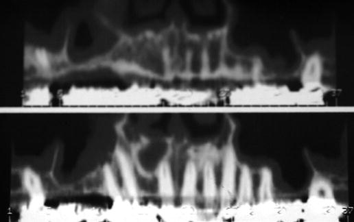
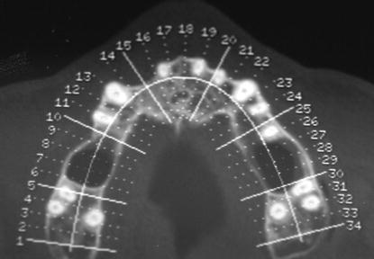
Figure 11.6 Preoperative CT scan (maxillary occlusal view). This slice was taken apical to the cementoenamel junctions (CEJs) of the maxillary molars. The three roots of the molars were clearly visible. The radiolucencies between the molars and the first premolar on the patient’s right side and the second premolar on the patient’s left side indicated the vertical depth of the sinus pneumatization.
Phase II was identified as surgical and interventional implant imaging and is used to evaluate surgical sites during and immediately after surgery. It also assists in optimal placement of implants and restorative components relative to the planned position of the teeth in the proposed prostheses.
Phase III was identified as postprosthetic implant imaging and commences immediately after implant and prosthesis placement. Phase III continues as long as the implants remain in the jaws. The objectives of this phase are to evaluate the long-term maintenance of implant rigid fixation and function, including crestal bone levels around each implant, and to evaluate the overall conditions of the implant/prosthetic complex (Figure 11.8).
Figure 11.7 This lateral slice of the CT was taken in the area of the missing maxillary right first molar after maturation of the bone graft into the right maxillary sinus. A simulated 5 mm diameter implant was drawn to simulate ideal implant placement. Note the bulk of bone that was added to the floor of the right maxillary sinus, compared to the minimal amount of bone present in the preoperative CT scans in Figure 11.5.
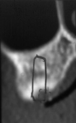
Figure 11.8 This is a digital periapical image of a 3-unit implant-retained prosthesis immediately after cementation. It served as the baseline phase III radiograph that is necessary to follow up on postinsertion bone levels and overall health of the implant/restoration complex.
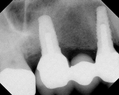
Figure 11.9 Typical example of a traditional panoramic radiograph taken as part of preprosthetic implant imaging phase I work-up for this patient.
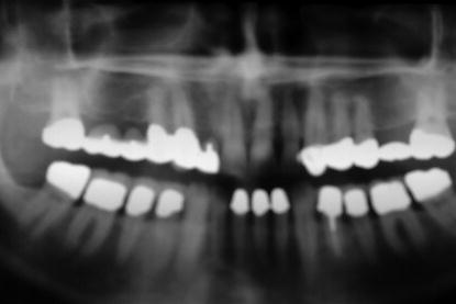
The bulk of preprosthetic imaging typically was done with panoramic radiography. Panoramic radiographs are made as a curved plane tomographic study that identifies the mandible, maxillae, and usually at least the lower half of the maxillary sinuses in a single film. Panoramic radiographs provide for qualitative data and are not considered to be diagnostic for exact replication of the physical anatomy because panoramic radiography produces images of sections of the jaws of variable thickness and magnification (Figure 11.9).
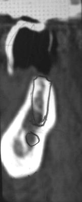
Figure 11.10 This particular lateral slice of the CT scan identified the precise location of the inferior alveolar canal and midportion of the planned implant restoration. Tentatively, a 5 × 11.5 mm implant was selected for this particular edentulous area.
Kircos (1990) identified the advantages of panoramic radiography as follows:
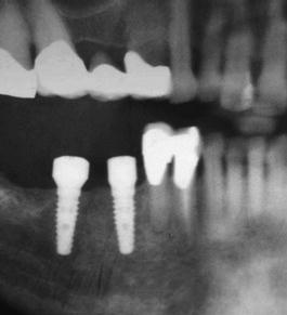
Tomography is a generic term that was adopted by the International Commission on Radiological Units and Measurements (1962) to describe all forms of body section radiography (DeLuca 2007). Body section radiography is a radiologic technique that enables visualization of a section of a body by blurring regions of the area of interest immediately above and below the section of interest. For dental patients, high-quality complex motion tomography examines the alveolus and, with magnification taken into consideration, enables quantification of the anatomy of the alveolus and related structures (Eckerdal & Kvint 1986). This type of radiographic study enables clinicians to determine the spatial relationship between critical structures and implant sites (Figure 11.10). Computed tomography (CT) scans have the requisite accuracy for surgeons to feel confident that their osteotomy preparations and implant placement will not encroach upon important anatomic structures. Ideally, tomographic sections of 1–2 mm allow evaluation of the proposed implant sites and permit visualization of the three-dimensional (3D) appearance of the alveolus and other anatomic structures (Figure 11.11).
Computed Tomography (CT)
CT is a digital imaging modality that creates tomographic sections where the layers are not blurred with artifacts from adjacent anatomic structures. CT allows differentiation between hard and soft tissues, thus allowing accurate images of the teeth, lamina dura, periodontal ligament spaces, cortical bone, and alveolar bone. CT produces axial images perpendicular to the long axis of the anatomy being examined. CT images are, by definition, 3D images, with thicknesses corresponding to the slice spacing of the particular imaging protocol. Each individual element of a CT image is called a voxel and has a value (Hounsfield units (HU)) that describes the density of the CT image. Each voxel contains 12 bits of data and ranges from −1000 (air) to +3000 (enamel/dental materials) HU. CT scanners are generally calibrated at a Hounsfield value of 0 for water. The CT density scale is quantitative and meaningful in identifying and differentiating structures and tissues.
Figure 11.11 This quadrant section of a panoramic radiograph was taken immediately post implant placement. The implants were placed with the benefit of CT treatment planning without violating the inferior alveolar canal and/or the mental nerve.
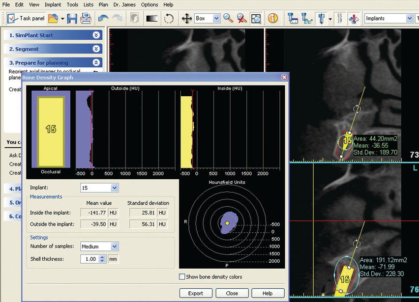
The efficacy of CT for imaging the maxillofacial region has been documented since its introduction in the 1980s (Helms et al. 1982). The differences in tissue densities can be used to differentiate tissues within each image and also characterize bone quality according to Lekholm and Zarb (1985), Shahlaie et al. (2003), and Lee et al. (2007) (Figures 11.12 and 11.13).
The improved diagnostic capabilities of CT, especially in regard to treatment planning for dental implants, have been well known for quite some time (Eckerdal & Kvint 1986; Stella & Tharanon 1990). However, access to CT scanners by dentists was limited, as was the interpretation of the scans by radiologists. The logistics of reformatting CT scans was laborious. The information was transferred to the referring dental practitioner for use, who may or may not have known how to interpret the studies. These difficulties led to the development of CT scanning for dental purposes. The new scans were identified as DentaScans (Kircos & Misch 2005).
Kircos and Misch (2005) identified the limitations of Dentascans:
Figure 11.12 Illustration of Type I (dense, cortical) through Type IV (soft, cancellous) bone.

Figure 11.13 This is a screen shot of a software program (SimPlant™ 12.0, Materialise Dental, Glen Burnie, MD, USA) used for presurgical treatment planning. The HU within the walls of the osteotomy averaged −141.77 and −39.50 outside the osteotomy. The low values were consistent with the anatomic location (posterior maxillae) and Type IV bone.
Interactive Computed Tomography (ICT)
Interactive computed tomography (ICT) addressed many of the limitations associated with CT (Van Steenberghe 2005). Digital scanning information can now be transferred to a disc from the imaging center. With the appropriate software program, clinicians can now develop treatment plans on their personal computers (Figure 11.14). Per Parel and Triplett (2004), ICT allowed for precise planning regarding implant positions; the images could also be used for construction of surgical guides and definitive prostheses prior to surgery. They found that this technology was powerful and easy to use and concluded that it will give clinicians significant advantages in treatment planning for implant dentistry.
Interactive Computer Software
The case in this chapter was performed using SimPlant 12.0 (Materialise Dental, Glen Burnie, MD, USA). This software program offers clinicians a solution for implant treatment from treatment planning to construction of surgical guides and provisional implant restorations (SurgiGuide Cookbook, 2007).
SimPlant software contains an open design feature in that the software is compatible with all CT and cone beam scanners. The software is also compatible with most major implant types and manufacturers. Implant designs and specifications are contained within the implant library; the library is updated on a regular basis.
Figure 11.14 This is a screen shot with the same software program noted in Figure 11.13. The views can be changed depending on the particular stage in the treatment planning process for a given patient. Different sized implants, from multiple implant manufacturers, are available in the implant library. Implants can be pasted into a given cross-sectional image and manipulated in terms of their 3D orientation for optimal positioning within the alveolus and in regard to the locations of the teeth.
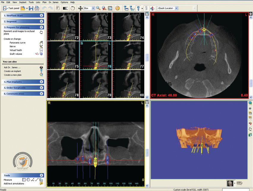
This software program allows construction of surgical guides that will be used during implant surgery by providing a link between the virtual treatment plan and the actual surgery (Figure 11.15). Guide tubes, in this case specific to the Biomet 3i Navigator™ System for CT Guided Surgery (Biomet 3i™, Palm Beach Gardens, FL, USA), will be placed into the surgical guides. The guides, according to the treatment plan, position the surgical drills into their correct positions (Figure 11.16).
Computer-Guided Surgery
Computer-guided surgery is a concept whereby surgical guides are fabricated from digitized data generated from the cone beam computed tomography (CBCT) scans and treatment planning. Computer-generated surgical guides can be fabricated to fit onto the teeth, soft tissue, or bone. Implant surgery may also be accomplished without reflecting full-thickness flaps because the anatomy has been identified with the CT scans. Flapless surgery has significantly less morbidity than implant surgery with full-thickness flaps. CT-guided surgery may be considered to be blind to the surgeon because of the lack of flap reflection.
Figure 11.15 Laboratory facial view of a tooth-supported surgical guide in place on a stereolithographically constructed model of a partially edentulous maxillary segment.
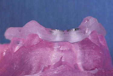
Figure 11.16 Notches within the occlusal surfaces of the master tubes can be visualized in this laboratory image of a computer-generated surgical guide.
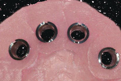
Soars et al. (2012) generated an in vitro model to test the precision of guided implant surgery. The accuracy of dental implants placed with a flapless protocol was analyzed using a stereolithographic template in vitro. Differences between virtual and actual positions of implants were measured. Six polyurethane mandibles with artificial silicone gingival tissues were fabricated; each model was fitted with a customized CT surgical guide. Stereolithographic guides were created using computer-aided design/computer-aided manufacturing (CADCAM) technology and virtual planning software. All stereolithographic guides had four holes for stabilization pins and three holes for cylindrical implants. After implant placement, the mandibles were scanned again to compare actual implant positions with the planned positions. The pre- and postimplantation CT images were superimposed using digital processing image software. Linear and angular deviations between the virtual planning data and the surgical results were computed. Soares et al. (2012) reported that the mean angular discrepancy between virtual and actual positions of the 18 implants was 2.16° ± 0.92°. Among the implants, 66.7% were placed a mean of 0.38 ± 0.03 mm apical to the planned vertical positions; 33.3% were situated 0.39 ± 0.03 mm coronal to the planned position. The authors concluded that within the limitations of their study design, computer-guided surgical implant placement showed promising accuracy.
Vasak et al. (2011) reported on the results of an in vivo study that evaluated overall deviations between virtual planned implants and clinical implant placement when a specific computer-generated surgical guide was fabricated (NobelGuide™, Nobel Biocare, Yorba Linda, CA, USA). Eighteen patients (male/female = 10/8) were enrolled in this clinical study with partially dentate and edentulous maxillae and mandibles. Overall, 86 implants were placed by two experienced dental surgeons strictly following the NobelGuide™ protocol for template-guided implantation. All patients had postoperative CT scans with identical settings to the preoperative examination taken. Using the triple scan technique, pre- and postoperative CT data were merged in the Procera planning software; measurements were made of the deviations at implant restorative platforms and apices for comparison. The deviations averaged 0.43 mm (buccolingual), 0.46 mm (mesiodistal), and 0.53 mm (depth) at the level of the implant restorative platforms; the measurements averaged slightly higher at the implant apices: 0.7 mm (buccolingual), 0.63 mm (mesiodistal), and 0.52 mm (depth). The maximum deviation of 2.02 mm was encountered in the vertical direction. Significantly lower deviations were seen for implants placed anteriorly versus posteriorly (P < 0.01, 0.31 vs. 0.5 mm). Mandibular mesial/distal deviations were also significantly lower than maxillary deviations (P = 0.04, 0.36 vs. 0.45 mm). The authors reported a significant correlation between deviation and mucosal thickness; a learning effect was also reported over time related to the actual performance of the surgical procedures.
OVERVIEW OF CT-GUIDED SURGICAL AND PROSTHETIC PROTOCOLS
Surgical Guides
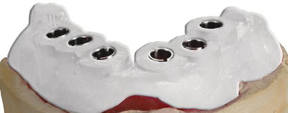
The surgical guide is the union of two components: guide tubes and the contact (intaglio) surface of the surgical guides. These data points were generated from the CT scan with a scanning appliance in place. The intaglio surface can be made to fit onto the edentulous jaw, the mucosal tissues covering a jaw, or the adjacent natural teeth (Figure 11.17). Due to the complex 3D shapes of jaws and teeth, the fit of each surgical guide is unique and stable. Surgical guides are made with resin, using a stereolithographic process, and are customized for each particular patient.
Figure 11.17 Laboratory image of the intaglio surface of a tooth-supported surgical guide with two master guide tubes in place in an anterior maxillary segment. The tubes were placed, and the surgical guide was fabricated consistent with the treatment plan developed in the computer software program.
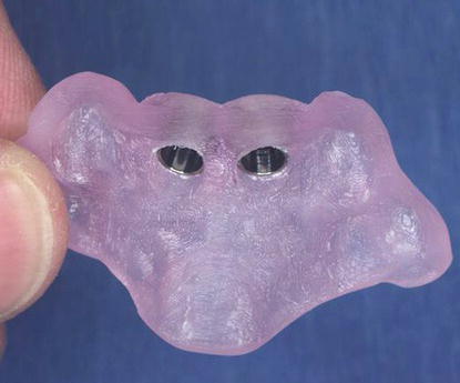
Figure 11.18 Laboratory illustration of a surgical guide with six master tubes in place.
Master Tubes
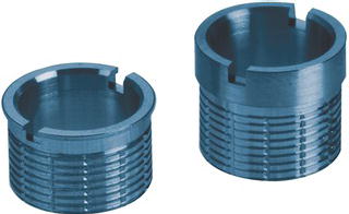
Master tubes are precision-machined metal tubes used with drills of specific diameters, through a given surgical guide, in locations determined during the treatment planning process (Figure 11.18). The tubes provide predetermined depth stops for the twist drills and implant mounts during surgical implant placement. Master tubes are machined with two notches, 180° apart (Figure 11.19). The notches were designed to provide positive interlocks with implant and analog mounts to ensure that the timing of the implant hex in implant analogs in a master cast is replicated with the timing of the implant hex intraorally.
Figure 11.19 Laboratory illustration of master tubes for 4 mm diameter implants. Master tubes are available in two heights to compensate for the prolongation involved in each particular case. Each tube is machined with notches 180° apart. The notches serve as reference points for hex orientation in the placement of implant analogs into master casts and implants into edentulous sites intraorally.
Prosthetic Laboratory Kit: Implant Analog Mounts
The Navigator Laboratory Kit for straight implants (Biomet 3i, Palm Beach Gardens, FL, USA) consists of implant analog mounts (Table 11.1) used in conjunction with master tubes in surgical guides to position implant analogs into the guides prior to pouring casts (Figure 11.20). The laboratory kit contains twelve analog mounts with an internal implant/abutment connection (Certain® Connection, Biomet 3i, Palm Beach Gardens, FL, USA). Mounts are available in three diameters (3.4, 4, and 5 mm) and four lengths identified as (1), (2), (3), and (4) (Figure 11.21). The laboratory technician will know which specific analog mount to use for each specific implant site because the mounts have been identified within the treatment plan (Figure 11.22). Analog mounts feature notches in the occlusal aspects of each mount as mentioned earlier, which hold the implant analogs in place within the three planes of space, including hex rotation, within the master tubes. Positive machinings in the analog mount thumbwheels fit into both notches of the master tubes to ensure accurate transfer of the hex orientation from the master cast to the mouth (Figure 11.23).
Surgical Kit Components
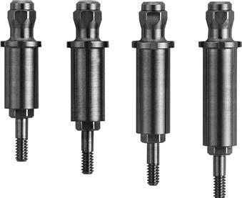
In order for a surgeon to place implants with this type of a surgical guide, implant mounts from the surgical kit are used to go through the master tubes in the surgical guide. These implant mounts were machined for use with Biomet 3i Certain Connection implants (3.4, 4, and 5 mm diameters); four lengths were machined as well and have been identified as (1), (2), (3), and (4) (Figure 11.24). There are therefore 12 unique implant mounts. Within one treatment plan, an implant mount may be used several times; five complete sets of implant mounts are available in each surgical kit (60 total mounts) (Figure 11.25). Implant mounts were designed to be depth specific, with a flange on the occlusal aspect of each mount for depth stops. A spline feature on the flange of each implant mount may be used as visual references during implant placement to orient the hex connection of each implant within the master tube. The cutouts of each flange are aligned with the slots on each master tube. This ensures the accurate transfer of the hex orientation from the preoperative master cast to the implants intraorally (Figure 11.26).
Table 11.1 Navigator Laboratory Kit for straight (cylindrical) implants.
| Components | Description | Item number |
| Laboratory kit | Complete Navigator Laboratory Kit | SGLKIT |
| Laboratory tray | Navigator Laboratory Tray | SGLTRAY |
| Navigator Certain® Analog Mount, MicroMiniplant™ × 1(L) | MSGIAM1 | |
| Navigator Certain® Analog Mount, MicroMiniplant™ × 2(L) | MSGIAM2 | |
| Navigator Certain® Analog Mount, MicroMiniplant™ × 3(L) | MSGIAM3 | |
| Navigator Certain® Analog Mount, MicroMiniplant™ × 4(L) | MSGIAM4 | |
| Navigator Certain Analog Mount, 4.1 mm(D) × 1(L) | SGIAM41 | |
| Navigator Certain Analog Mount, 4.1 mm(D) × 2(L) | SGIAM42 | |
| Navigator Certain Analog Mount, 4.1 mm(D) × 3(L) | SGIAM43 | |
| Navigator Certain Analog Mount, 4.1 mm(D) × 4(L) | SGIAM44 | |
| Navigator Certain Analog Mount, 5 mm(D) × 1(L) | SGIAM51 | |
| Navigator Certain Analog Mount, 5 mm(D) × 2(L) | SGIAM52 | |
| Navigator Certain Analog Mount, 5 mm(D) × 3(L) | SGIAM53 | |
| Navigator Certain Analog Mount, 5 mm(D) × 4(L) | SGIAM54 |
Figure 11.20 Laboratory illustration of the Navigator Laboratory Kit (straight implants). Implant analog mounts are available for 3.4, 4, and 5 mm diameter internal connection implants. They have been machined in 4 lengths, corresponding in length to the implant mounts in the surgical kit. Reproduced with permission of Biomet 3i.
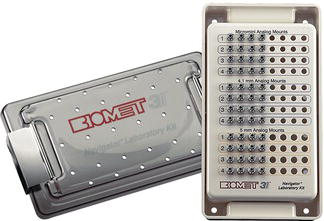
Figure 11.21 Laboratory illustration of four implant analog mounts in four different lengths. Laboratory technicians will identify each specific mount for use within the surgical guide from the treatment plan.
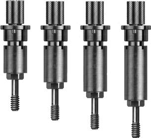
Figure 11.22 Photograph of a treatment plan of a patient to be treated with a CT-guided surgical protocol. The bottom two lines are the laboratory portion of the treatment plan. These two lines indicated which implant analog mounts should be used with which specific implant analog, in each specific implant site.
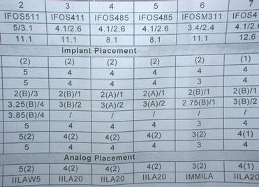
Figure 11.23 Laboratory illustration of two implant analog mounts within a surgical guide. The left implant analog mount was not completely seated within the master tube; the right implant analog mount was correctly seated within the master tube.
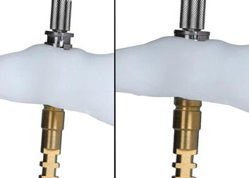
Figure 11.24 Laboratory illustration of four implant mounts in four different lengths. The use of each implant mount will be identified in the surgical portion of the treatment plan and identifies each specific mount for use within the surgical guide from the treatment plan.
Fabrication of Master Cast for Immediate, Fixed Provisional Prosthesis
The appropriate implant analogs and implant analog mounts are selected as identified in the treatment plan. Implant analog mounts are placed into implant analogs, the hexes are aligned, and the thumbscrews are threaded for approximately two turns. The analog mount/implant analogs are placed through the master tubes in the surgical guide, consistent with the implant sites in the treatment plan. The preceding components are aligned with the notches in the master tubes, and the thumbscrews are completely hand tightened. Note: it is important not to overtighten the aforementioned complexes before placing them into the master tubes as this may damage the analog mounts (Figure 11.27).
Figure 11.25 Laboratory illustration of the surgical kit for straight implants. Implant mounts are in the second, deeper layer of the kit. A portion of the implant mounts for 4 mm diameter and all of the implant mounts for 5 mm diameter implants are visible in this figure. Reproduced with permission of Biomet 3i.
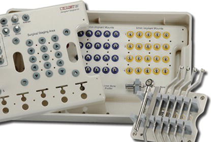
Figure 11.26 Laboratory illustration of two implant mounts within a surgical guide. The left implant mount was not aligned properly with the notches within the master tube; the right implant analog mount was correctly aligned with the notches within the master tube.
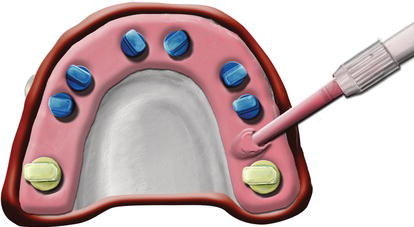
A stone separating material is applied to the intaglio surface of the surgical guide. Box the surgical guide as if it were an impression and inject a soft tissue replicating material around the implant analogs in conventional fashion (Figure 11.28). Vacuum mix dental stone consistent with the manufacturer’s instructions for weight and water volume; pour the master cast.
Figure 11.27 Laboratory illustration of implant analogs accurately positioned in a surgical guide. The blue analogs are 4 mm in diameter; the gold analogs are 5 mm in diameter. All of the analog mounts have been accurately positioned within the master tubes.
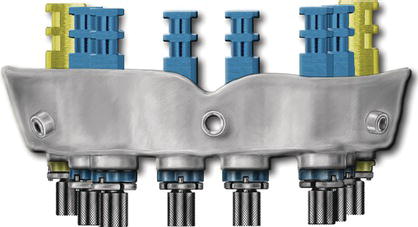
Figure 11.28 Laboratory illustration of soft tissue replication material injected around implant analogs within a surgical guide.
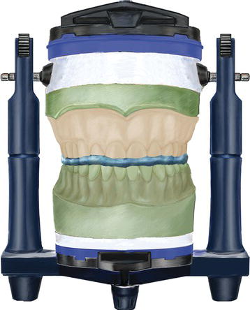
Place the scanning appliance onto the aforementioned master cast. Verify that the scanning appliance has been completely seated. Articulate the master cast with the opposing cast by using the previously made interocclusal record for the scanning appliance; mount the casts in a semiadjustable articulator (Figure 11.29).
Abutment Selection for Fixed, Screw-Retained Provisional Prostheses
Abutments for immediate, full-arch prostheses are generally chosen by the restorative dentist and dental laboratory technician. With CT treatment planning, the abutments may actually be selected with reasonable certainty during the treatment planning process. Prostheses may be either cement or screw retained; abutments are chosen consistent with those designs. The benefits and limitations regarding cement- and screw-retained restorations have been previously discussed in Chapter 1 and will not be repeated here.
Figure 11.29 Laboratory illustration of the newly made maxillary master cast, articulated with the opposing mandibular cast, with an interocclusal record in a semiadjustable articulator. The maxillary scanning appliance was fit to the maxillary master cast prior to the articulator mounting.
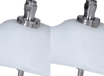
For screw-retained prostheses, the authors prefer the conical abutment series of abutments from Biomet 3i (Palm Beach Gardens, FL, USA). They are available in straight, 17°, and 25° preangled configurations (Figure 11.30). Collar heights for each abutment are selected by measuring the sulcular depths around each implant analog in the master cast. If subgingival margins are desired, subtract 1 mm from the sulcular depth measurements. Next, select the appropriate angulation: straight or 17° or 25°. In CT-guided surgery, this has already been determined from the software treatment planning program (Figure 11.31). Allow approximately 2 mm of interarch distance between th/>
Stay updated, free dental videos. Join our Telegram channel

VIDEdental - Online dental courses


