10
Transverse and Asymmetry Corrections
Asymmetry problems
Mini-implant anchorage is invaluable for the correction of substantial asymmetry problems in all three planes of space, especially since it is now feasible to alter vertical dentofacial asymmetries which would otherwise be accepted with standard treatment or deemed to require orthognathic surgery. Conventional antero-posterior anchorage reinforcement involves connections on both sides of the arch (e.g. a TPA), which may be unnecessary, and even contra-indicated when fundamentally different movements are required in each quadrant. In comparison, mini-implant usage means that anchorage is only reinforced in the specific quadrant and direction(s) indicated for optimal treatment changes. For example, full correction of a large dental centreline displacement to the right side of the facial midline may require a unilateral mini-implant placed mesial to the upper left first molar (Fig. 10.1a). Furthermore, in such cases unilateral mini-implant anchorage helps with treatment efficiency by enabling ‘multi-tasking’, e.g. alignment of a palatally displaced lateral incisor at the same time as fully active bodily retraction of the contralateral canine (Fig. 10.1b) or space closure in the contralateral quadrant. This chapter describes unilateral mini-implant usage for the following applications:
- centreline (transverse) correction
- unilateral intrusion (vertical asymmetry correction)
- ectopic tooth alignment (transverse correction).
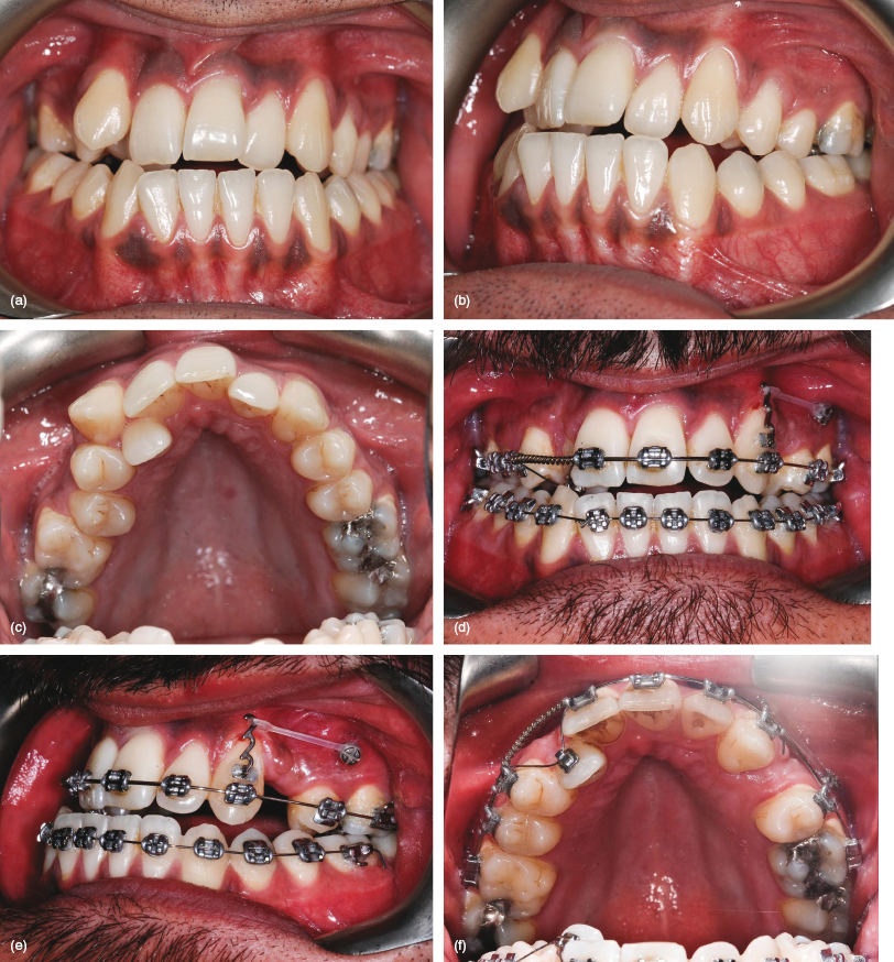
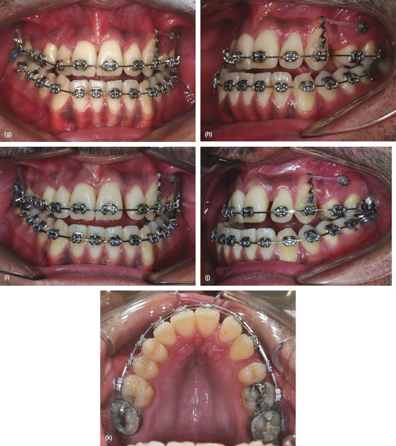
Figure 10.1 A Class III case requiring extraction of the upper right canine (at risk of labial dehiscence) and left first premolar teeth, maxillary arch alignment and centreline correction prior to orthognathic surgery. (a–c) Pre-treatment views showing the Class III malocclusion, palatal exclusion of the upper right lateral incisor and left Class II canine relationship. (d–f) Traction applied from a mini-implant, inserted mesial and buccal to the upper left first molar, to a powerarm bonded on the left canine crown. Simultaneous alignment of the right lateral incisor commences, with a combination of 0.018 steel base archwire and 0.012 piggyback sectional NiTi. (g, h) Bodily distalisation of the canine continues when a 0.018 NiTi archwire is used for further lateral incisor alignment. (i–k) Leftwards incisor traction applied in addition to canine movement, on insertion of a 0.019 × 0.025 NiTi archwire, without rollercoaster bowing of the left buccal teeth.
Dental Centreline Correction
Clinical objective
- Asymmetrical anchorage reinforcement to facilitate unilateral movement of the incisor teeth.
Treatment options
- Unilateral posterior (direct) mini-implant anchorage.
- Indirect mini-implant anchorage, e.g. stabilisation of a Nance palatal button so that unilateral traction can be applied from a molar band (as described for bilateral traction in Chapter Six).
- Conventional anchorage involving bilateral intra-oral reinforcement or asymmetric headgear.
- Asymmetrical intermaxillary elastic traction.
- Asymmetrically activated functional (orthopaedic) appliances.
Relevant clinical details
- Many patients display asymmetry in several dimensions rather than just one, although one plane may predominate. Therefore the diagnostic process should determine both the extent and nature of the transverse and vertical contributions to the whole asymmetry. In particular, is the asymmetry panfacial or localised, dental or skeletal, and is a functional mandibular displacement present? A frontal poster-anterior cephalometric view or CBCT scan may be useful.
- The incisor (overjet, overbite) and canine relationships.
- The dental centrelines relative to the facial midline and (the lower one) to the mandibular midline.
Biomechanical principles
- Determine the ideal traction vector prior to mini-implant insertion. For example, if there is sufficient height of attached gingiva then the mini-implant may be sited at a relatively apical (‘high’ vertical) level. This provides the option of supplementary vertical intrusive traction, although a powerarm may be required to prevent unwanted vertical side-effects due to an oblique vector of antero-posterior traction. Conversely, if there is only a narrow band of attached gingiva then the mini-implant is limited to a coronal insertion level, resulting in closer proximity to the archwire plane and a relatively horizontal line of traction, but little scope for intrusive effects.
- Indirect (mid-palate) anchorage of a Nance palatal button involves force application from the fixed appliance molar hook. This means that the biomechanical effects are similar to conventional straight wire treatment.
- Transverse centreline correction involves either en masse incisor movements on a rigid (0.019 × 0.025) steel archwire, or the use of canine powerarm to enable movements on ‘lighter’ (e.g. 0.018) archwires (Fig. 10.1).
Clinical tips and technicalities
- Growing patients with reduced maxillary bone support (due to low density/thickness of the cortical plate) may be treated with indirect anchorage since the mid-palate cortex provides adequate stability in adolescents.
Mid-treatment problems and solutions
- Vertical side-effects such as a lateral openbite and excessive incisor retroclination:
- Avoid the application of traction with a flexible archwire in situ or when a working steel archwire (e.g. 0.019 × 0.025) hasn’t fully levelled the arch.
- Add a unilateral curve to the working archwire on the traction side, i.e. a curve of Spee to a maxillary archwire and a reverse curve to a mandibular one.
- Accept the openbite side-effect until anchorage is no longer required, then remove the mini-implant, bond the second molar in the affected quadrant, and use a flexible archwire to level the arch.
- Vertical settling elastics may also be added although most lateral openbites readily settle once traction has ceased and the archwire changes are expressed.
Pre-insertion
Mini-implant selection
Insertion
Post-insertion
- This 27 year old female presented with a Class II division 2 malocclusion on a mild skeletal II base (Figs 10.2a–d). She had transverse skeletal asymmetry with the chin point displaced to the left side (without a functional displacement) and a subtle degree of vertical asymmetry (occlusal cant slightly higher on the left side). The upper incisor–lip relationship was aesthetically satisfactory. The upper right canine and the first premolars from the other three quadrants were absent. The upper and lower dental centrelines were displaced to the right and left sides, respectively, and the buccal segments exhibited similar asymmetry, including a ¾ unit Class II relationship of the left canines.
- Both arches were initially levelled and aligned. The left Class II canine relationship, deep overbite and lower centreline problems were additionally corrected by the use of pushcoil to re-open the lower left first premolar space.
- Asymmetrical anchorage was reinforced using 6 and 9 mm length mini-implants inserted mesial to the lower left canine and upper left first molar, respectively (Figs 10.2e–g). Direct traction was applied to pull the maxillary incisors towards the left, whilst indirect anchorage was utilised in the mandibular arch, since the insertion site was anterior to the canine. This involved a 0.019 × 0.025 steel auxiliary wire and a cross-tube connecting the mini-implant and the main archwire. Elastomeric traction was used to protract the lower left molars.
- The patient declined to correct the vertical asymmetry, so the mini-implants were removed once the left molar relationship had been over-corrected so that finishing alignment could be performed (Figs 10.2h–j). This was followed by asymmetrical traction, predominantly Class III elastics on the right side, although a small residual centreline discrepancy was accepted due to tooth size discrepancies (Figs 10.2k–n).
Figure 10.2 (a–d) Pre-treatment views showing this Class II malocclusion with absence of the upper right canine and first premolars in the other three quadrants, asymmetric buccal segment relationships and centreline discrepancies. (e–g) The lower left premolar space has re-opened during alignment and lower centreline correction. Upper posterior and lower anterior mini-implants are being used for upper centreline correction and lower molar protraction, respectively. Indirect anchorage is used to provide a horizontal vector of traction from a 0.019 × 0.025 steel auxiliary wire (connected vertically between the archwire and mini-implant head). (h–j) Finishing alignment and then asymmetric settling elastics are used after removal of/>
Stay updated, free dental videos. Join our Telegram channel
VIDEdental - Online dental courses


