CHAPTER 10 THE USE OF CT/CBCT AND INTERACTIVE VIRTUAL TREATMENT PLANNING AND THE TRIANGLE OF BONE
DEFINING NEW PARADIGMS FOR ASSESSMENT OF IMPLANT RECEPTOR SITES*
During the past 20 years, an emerging technology encompassing computed tomography (CT), cone beam computed tomography (CBCT), and interactive treatment planning software has slowly evolved into a necessary tool for diagnosis, treatment planning, and delivery of dental implant and associated restorative and surgical procedures. The integration of these innovative tools has helped to define new paradigms for appreciating anatomy, improving accuracy, and enhancing presurgical prosthetic planning to achieve true restorative-driven implant dentistry. In the past, the standard tools for diagnosis and treatment planning were two-dimensional (2-D) periapical and panoramic imaging.1–4 The dental implant literature is replete with prescripts and determinants for proper placement and angulation, methods to preserve interdental papilla, and implant-to-tooth and implant-to-implant parameters.5–12 However, until recently all documentation was based on 2-D radiography or direct clinical examination at the alveolar crest, which could not allow a complete assessment of the patient’s anatomy or spatial position of the implant.
Recent advances in CT and CBCT technology, combined with the evolution of interactive virtual treatment planning software applications, have empowered clinicians with enhanced diagnostic capabilities for implant receptor-site assessment. These innovative tools have allowed new paradigms to be developed, which may supersede current methods of presurgical planning for dental implant reconstruction.13–19 The concepts as presented in this chapter are related to missing maxillary lateral incisors—single-tooth replacements. Many clinicians do not see the value in scanning patients who are missing a single tooth because they feel that the anatomy is self-evident. However, without the ability to visualize in three-dimensional (3-D), and virtual interactive treatment planning tools, the anatomy is often anything but self-evident. It is the intent of this chapter to introduce treatment planning methodologies that will define new paradigms that are universally applied to a variety of clinical presentations for partially and fully edentate patients.
 Congenitally Missing Laterals
The patient’s medical history was unremarkable, and the patient was found to be healthy and a good potential candidate for dental implants to replace the missing lateral incisors. Periapical radiographs were taken to help determine the mesial-distal inclinations of the adjacent tooth roots (Figure 10-1, A). The radiographs revealed a serious issue: convergent roots for the right canine and right central, which eliminated that area as a potential implant-receptor site. The space between the left central and canine teeth was minimal, although the roots were relatively parallel. Clinical examination (manual palpation of the root eminences superiorly to the vestibule on the right side) confirmed the root convergence (Figure 10-1, B). The flat, wide zone of the keratinized tissue and lack of interdental papilla were evident for the missing right lateral incisor. There was a marked difference in clinical appearance for the left lateral, which could impact the eventual plan of treatment (Figure 10-1, C). Other significant clinical findings included bilateral facial bone concavities, that existed as a result of the congenitally missing tooth roots. As a diagnostic cue to the underlying bone topography, it is important to follow the demarcation between attached and unattached gingival tissue, and note the crestal width of the available keratinized tissue (Figure 10-1, D).

Based on the intraoral examination and periapical radiographs, additional orthodontic intervention was recommended to move and rotate the roots to gain enough space for implant placement. This information was conveyed to the parents and the treating orthodontist. After several additional months, a panoramic radiograph was provided by the orthodontist to evaluate the distance between the clinical crowns and tooth roots (Figure 10-1, E). The lack of sharpness, definition, and radiographic artifacts made it impossible to determine whether implants could be successfully placed based on the 2-D panoramic image. This diagnostic predicament was discussed with the patient and his parents, and it was suggested that a CT scan would be necessary to accurately assess the bone topography and spatial orientation of the adjacent roots. The parents agreed, and the patient was given a prescription for a CT scan study at a local radiology center.
In the “Zone” with the Triangle of Bone
Using the interactive treatment planning software application, the scan data were assimilated and both potential lateral incisor implant receptor sites were evaluated. A combination of the data and the methodology used to interpret the data are the basis for defining a new paradigm in diagnosis and treatment planning. Proper evaluation of these images and correct use of the interactive treatment planning software tools are essential in creating a decision tree of treatment options. First, the data from the scan were reformatted into panoramic, axial, and cross-sectional images. The undistorted cross-sectional images revealed the residual alveolar bone in the area of the right lateral incisor. Then, a simulated schematic implant was placed within the bone with an abutment extension to help visualize the connection to the restorative position of the tooth (Figure 10-2, A).
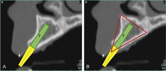
The Triangle of Bone (TOB), a concept developed by the author to analyze bone quality, quantity, and disposition at prospective dental implant sites using CBCT scans, aided in determining available bone volume by defining a zone for proper implant placement20–22 (Figure 10-2, B). The TOB concept creates a decision tree of seven basic parameters for proper treatment planning (Box 10-1). These seven parameters should not serve as the final assessment based on only a single image. Rather, the information should be evaluated and assimilated to gain an appreciation of all available images, including the axial, cross-sectional, panoramic, and 3-D reconstructions. These parameters include the following:
Because the goal of implant dentistry is not the implant but the tooth that is placed, true restorative-driven implant dentistry must begin with the assumption that the implant position should remain consistent with the tooth it is replacing and the final implant supported restoration.14,25–29 The TOB aids the clinician in understanding the link between the implant position and the desired restorative goal. The base of the geometric TOB zone is visualized by starting at the widest area of alveolar bone facially and superiorly. The apex of the triangle is positioned to bisect the alveolar crest (see Figure 10-2, B). The TOB, the overlay in the cross-sectional image, reveals whether adequate bone is available for implant placement. It also helps to identify concave facial bone defects and accurately determine the width of bone at the crest. The author recommends using an interactive software application that provides the necessary measurement tools to accurately assess the bone anatomy.
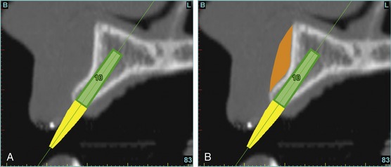
This case contained bilateral concavities, which led to three treatment options (1) place the bilateral implants and do nothing about the concavity and lack of root eminence; (2) place a soft-tissue graft to plump out the tissue to simulate a root eminence; or (3) add bone to fill out the defect. Additional suboptions also came into play, such as the type of bone graft procedure (allograft or autogenous, particulate cancellous or cortical particles, block graft). The left lateral site revealed a thinner facial-lingual crestal dimension (Figure 10-3, A). The simulated implant was placed within the TOB, and a simulated bone graft (presently available as an upgrade tool for SimPlant) was added to the facial, helping determine the proper course of treatment (Figure 10-3, B).
The Restorative Dilemma
The CT axial views represent an important instrument in gaining a better understanding of anatomical features that cannot be determined by any other imaging modality (Figure 10-4, A). When the maxilla is sliced at the level where the roots meet the crest of the bone, the adjacent and surrounding root morphology can be revealed. The axial images allow the true root and tooth anatomy of each dental arch to be visualized and appreciated in a modality unique to CT/CBCT imaging. Of note are the individual shapes of each of the maxillary central incisors, canines, premolars, and molar roots. These images reflect a phenomenon defined by the author as the “restorative dilemma.”22 Clinicians encounter this often difficult dilemma when attempting to reestablish morphologically correct emergence profiles in prosthetic teeth as they ascend from the round shape of the implant(s). The restorative dilemma is therefore the necessary obstacle encountered when clinicians try to move from the round implant at the bone level, through the tissue to support the prosthetic tooth with the available restorative components. This often necessitates what the author has termed “prosthetic gymnastics,” or the labor intensive operation that is often required to correct an off-trajectory implant position linking the implant to the tooth.
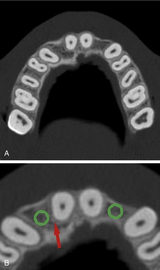
When planning for the placement of the implant in the left lateral incisor area, there appeared to be adequate mesial-distal space between roots, as seen in the axial view of Figure 10-4, B. A closer inspection of the planned site for the right lateral incisor revealed a narrower space, further complicated by the distal rotation of the palatal aspect of the tooth root. Based on this preliminary position, the 3.75-mm-diameter, straight-walled implant can be seen encroaching on the lamina dura periodontal ligament space of the right canine and central incisor. Inadequate space for this diameter and type of implant could lead to iatrogenic damage in the adjacent teeth. Therefore, additional tweaking of the virtual placement was necessary to diminish this risk. The ability to assess the root morphology and the lamina dura empowers the clinician with an improved diagnostic appreciation of the planned receptor site.
Confirmation With Interactive 3-D Imaging
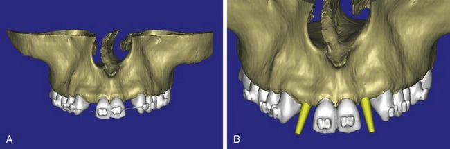
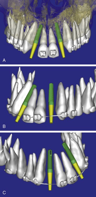
After the basic plan had been established, it was reevaluated using interactive 3-D images. The reconstructed 3-D view of the maxilla clearly illustrated the extent of the bilateral facial concavities and the root eminences of the adjacent and posterior teeth (Figure 10-5, A). The placement of the virtual implants then was evaluated to ensure that the facial cortical plate was not perforated (Figure 10-5, B). The implants were labeled individually as “7” and “10,” with the simulated yellow abutment projection indicating the facial-lingual inclination through the bone to the level above the incisal edge of the adjacent teeth. The ability to gain a better understanding of these individual root forms cannot be underestimated. The dental literature has suggested certain parameters for placing implants near teeth and implants next to other implants. However, there is little scientific 3-D documentation to support these suggested rules.5–12 The use of an interactive treatment planning software application permits closer scrutiny of previously difficult-to-visualize areas, and can now be used to redefine perceptions of spatial positioning of implants, especially those in proximity to natural tooth roots, vital anatomy, and adjacent implants.30–32
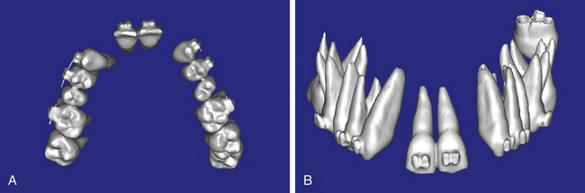
Using different masking (segmentation) and threshold Hounsfield unit values, several new 3-D bone volumes can be created that offer invaluable information. To help determine the final position of each implant a new bone model was created with a Hounsfield unit value of 1480, which eliminated all but the densest objects included in the scan data. (Results may vary depending on the CBCT machine used.) The inner and outer layers of bone were removed, leaving the underlying enamel and root structure of the teeth (Figure 10-6, A). After the bone had been stripped away, the root inclinations were examined closely. The most striking findings confirmed the rotated position of the right central, while revealing the slight mesial dilaceration of the root apex, which converged on the space needed for the path of the potential implant (Figure 10-6, B). The schematic shapes of the proposed implants were visualized for the right and left lateral spaces in different rotations of the 3-D maxillary arch. At this point a determination was made as to the appropriate implant shape and type to fit the available space while avoiding encroachment on adjacent tooth roots. A tapered design implant (Tapered Screw-Vent, Zimmer Dental, Carlsbad, CA) was chosen from the large virtual library with the SimPlant software. The virtual library contains data from dozens of implant manufacturers and realistic computer-aided design representations, as seen in Figure 10-7, A, through the translucent bone. The position of the left implant can be visualized with adequate mesial-distal distance between adjacent tooth roots (Figure 10-7, B) with a more delicate placement (Figure 10-7, C).
Stay updated, free dental videos. Join our Telegram channel
VIDEdental - Online dental courses


