CHAPTER 10 Computer-Guided Surgery
The growing interest in flapless surgery in conjunction with immediate loading for edentulous patients has led to the development of software programs that assists treatment planning, fabrication of a surgical template, and production of a prosthesis that can be secured to the patient immediately following implant placement. The protocol for the two-scan technique1 and use of the NobelGuide software has been described in recent literature.2–4
Material and Method
Scanning Protocol
To visualize the relationship of the patient’s prosthesis to the edentulous ridge, the “two-scan” technique is used.5 To begin this protocol, radiopaque markers are added to the patient’s denture; these will be recognized by the computed tomography (CT) scanner.
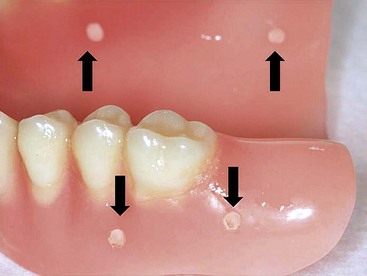
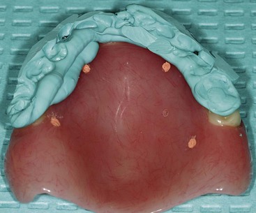
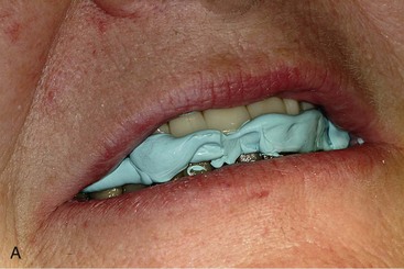
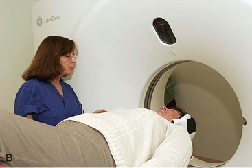
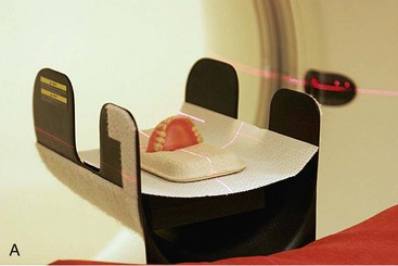
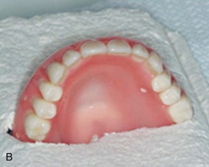
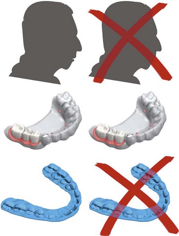
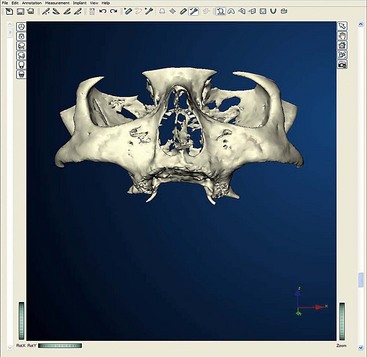
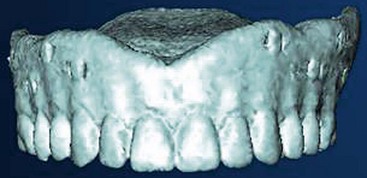
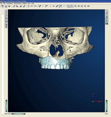
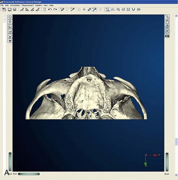
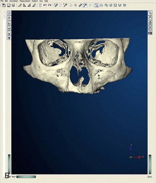
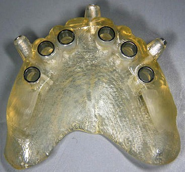
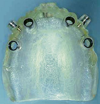
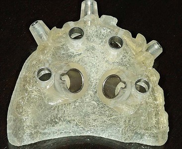
After confirming proper fit, proper vertical dimension of occlusion, and proper anterior-posterior tooth position, gutta-percha markers are added to the patient’s denture (Figure 10-1). A minimum of six gutta-percha markers are “staggered” (Figure 10-2). Each marker is approximately 2 mm in diameter and 1 mm deep. Bite registration material is used to ensure uniform and reproducible seating of the denture onto the edentulous ridge during the scanning procedure (Figure 10-3). The initial CT or cone beam CT scan is performed with the patient wearing the denture and occluding into the bite registration material (Figure 10-4). The second scan is of the denture only (Figure 10-5). Figure 10-6 demonstrates the schematic of the two scans. The raw data is referred to as Digital Imaging and Communications in Medicine (DICOM) files, which are then copied onto a compact disc and labeled as “patient DICOMs” and “denture DICOMs.” These two-dimensional DICOM files are imported for analysis and treatment planning within the guided surgery program of choice. The first scan, the patient DICOM file, is imported into the guided surgery software and is converted to a three-dimensional representation (Figure 10-7). The second scan, the denture-only DICOM file, is also imported and converted into three-dimensional format (Figure 10-8). The two three-dimensional scans are merged and superimposed onto each other by overlaying the gutta-perch points of the first scan with the corresponding gutta-percha points on the second scan, relating the patient’s edentulous jaw to the denture, which can be visualized on the same screen (Figure 10-9).
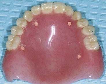
FIGURE 10-1 A properly fitting full denture is fabricated in preparation for a computed tomography scan.
The next sections summarize the uses of computer-guided software as a:
Step 1: Planning
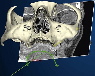
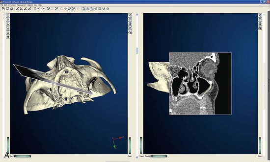
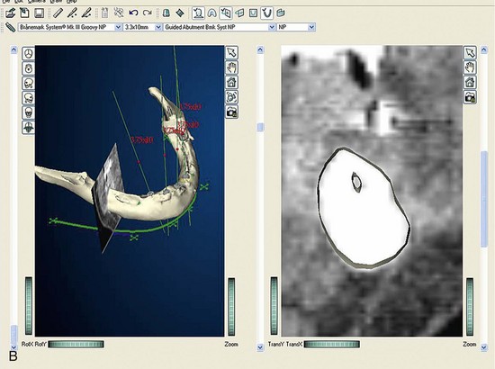
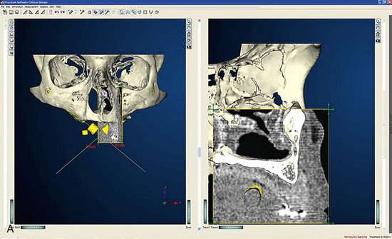
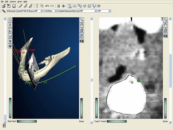
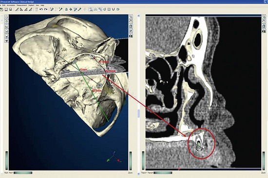
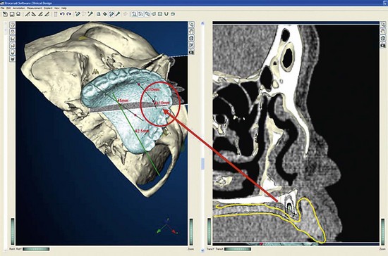
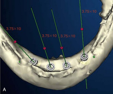
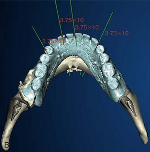
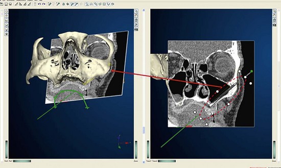
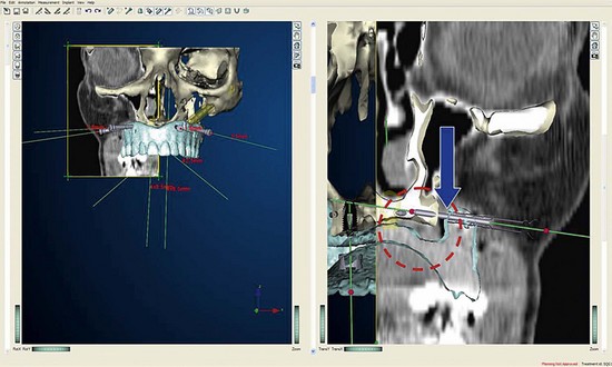
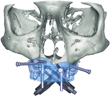
Once the patient and denture DICOM files have been imported and converted to three-dimensional images, the comprehensive analysis of the patient’s bony topography can be made by manipulating the image (Figure 10-10). The virtually planned implant position has been studied and compared with the transfer-planned position (the final surgical position), and has been found to be remarkably accurate and predictable.6 To begin planning implant placement within the remaining bony housing of the alveolus, a two-dimensional window is opened, allowing visualization of the remaining horizontal bony topography (Figure 10-11). A systematic visualization of the posterior alveolus, including the maxillary sinus in the maxilla and the inferior alveolar nerve in the mandible, can be made (Figure 10-12). The premaxilla and the mandibular symphysis can be evaluated for remaining alveolar bone volume (Figure 10-13). The practitioner can click off the image of the patient’s prosthesis, and the implant is positioned in the desirable surgical position (Figure 10-14). The practitioner can click on the image of the patient’s denture to see the position of the planned implant axis (Figure 10-15). If the surgical position complements the prosthetic position, the next implant is planned. However, if a conflict exists, the practitioner clicks off the image of the prosthesis, and the implant is manipulated as many times as necessary to coincide with the desired prosthetic emergence profile. The same protocol is followed for planning mandibular implants (Figure 10-16) as well as for planning the position of zygomatic implants (Figure 10-17).
Step 2: Fabrication of Surgical Template
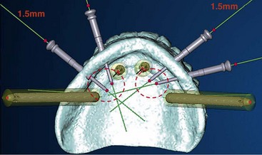
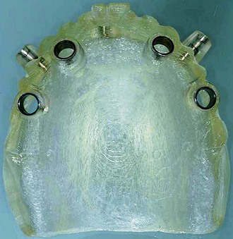
Once the virtual planning of the implants has been completed (Figure 10-18), surgical template planning is initiated (Figure 10-19). Stabilization of the surgical template to the patient is achieved by use of anchor pins. This essential step must be performed before initiation of the osteotomies to allow for the execution of the virtual planned implant positions to the patient. Once the implant positions as they relate to the edentulous alveolus and the prosthesis have been completed and are satisfactory to all team members, position planning for anchor pins begins (Figure 10-20). Three to four anchor pins are strategically placed between the planned implant positions (Figure 10-21), keeping in mind the axial projection of the existing implants. Anchor pin depths are controlled to ensure that the anchor pin sleeves do not project beyond the intaglio surface of the denture (Figure 10-22). Improper anchor-pin placement can potentially prevent proper seating of the denture onto the edentulous ridge. Prior to completion of this planning phase, the bony window is “turned off” to visualize the relationship of the implants with the anchor pins to ensure that they do not collide (Figure 10-23). Once the proper depth of the anchor pin sleeves into the flange of the denture and the depth of the anchor pin itself into the patient’s bone are confirmed, a template is produced by proceeding to the next step in the software. The completed surgical plan is sent for fabrication of the surgical template (Figures 10-24, 10-25, and 10-26).
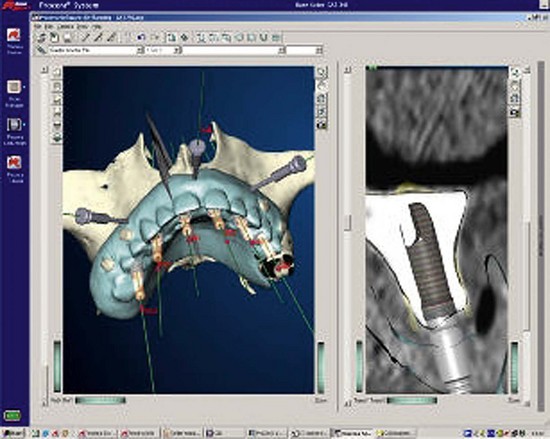
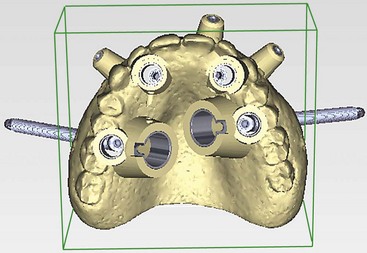
FIGURE 10-18 Completed “virtual” planning, demonstrating the position of the implants and anchor pins.
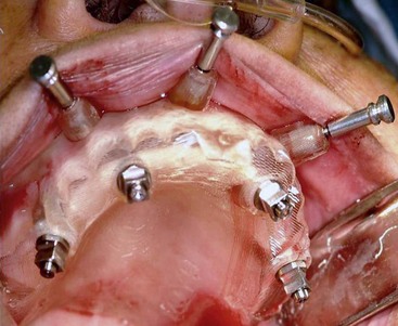
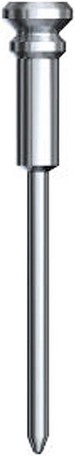
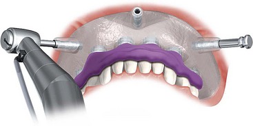
FIGURE 10-21 A minimum of three anchor pins stabilize the surgical template during preparation of the osteotomies.
(Courtesy Nobel Biocare, Yorba Linda, Calif.)
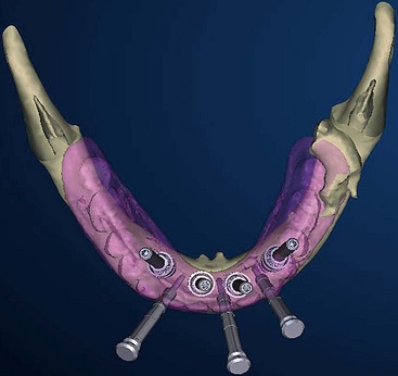
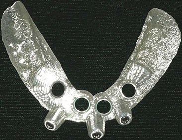
For the mandible, the tilted concept is used to support a mandibular fixed-profile prosthesis (Figure 10-31).
If the practitioner chooses, after implant placement, temporary healing abutments may be placed during a soft reline of the patient’s full denture. The implants will be allowed to osseointegrate for 3 to 6 months before proceeding with fabrication of the final prosthesis. If the practitioner chooses to immediate-load the implants after placement with the guided template, the analogue techniques described in Chapters 6, 7, or 8 can be used (Figure 10-32). The following section describes the steps needed to prepare a prefabricated immediate-load prosthesis.
Step 3: Fabrication of Provisional Immediate-Load Prosthesis
Complete use of computer-guided surgery software includes preoperative fabrication of an immediate-load prosthesis. Fabrication of the prosthesis begins after receiving the surgical template (Figure 10-33). The surgical template, a stone model of the apposing arch and a duplicated denture of the edentulous jaw planned for implant placement, is sent to the laboratory. The next section describes the steps taken in the laboratory: pouring the master model and fabricating the provisional immediate-load prosthesis.
Laboratory Steps
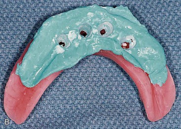
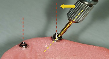
Delivery of the completed surgical template to the laboratory technician begins the next phase of treatment with computer-guided surgery. The initial step in the laboratory process is fabrication of a master cast. To pour the master model, special components are needed; these are the guided sleeve, the guided pin, and the implant replicas (Figure 10-34). The guided sleeves duplicate the platform position of the fixture-level implant replica to the surgical template. It is important for the laboratory technician to accurately position and completely seat the three fixation pins within the surgical template prior to pouring the master model (Figure 10-35). The fixation pins orient the position of the surgical template to the master model and in turn dictate the position of the provisional prosthesis in three dimensions. The same three fixation pins are used to stabilize the surgical template to the patient during the surgical procedure (Figure 10-36). Accuracy in management of the fixation pins is critical to ensure proper orientation and occlusion of the provisional prosthesis in the patient’s mouth following implant placement. The laboratory technician can now pour a soft tissue model (Figure 10-37).
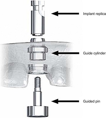
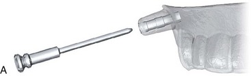
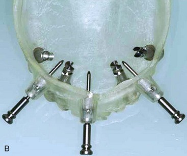
FIGURE 10-35 Laboratory anchor pins are placed through the anchor pin sleeves of the surgical template.
(B courtesy Nobel Biocare, Yorba Linda, Calif.)
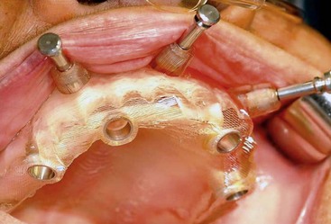
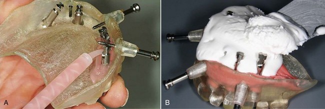
FIGURE 10-37 A, The soft tissue portion of the master model is poured. B, The stone portion of the master model is poured.
The second step is mounting the newly fabricated master cast (Figure 10-38). To mount the master cast, a previously mounted stone model of the patient is required to establish the patient’s acceptable vertical dimension of occlusion.7 To treat a patient with an edentulous maxilla, master cast orientation is achieved by placing the patient’s clear, duplicated maxillary denture onto the master cast and articulating it with the mounted apposing cast on the articulator (Figure 10-39).
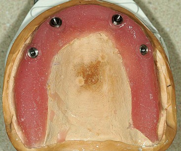
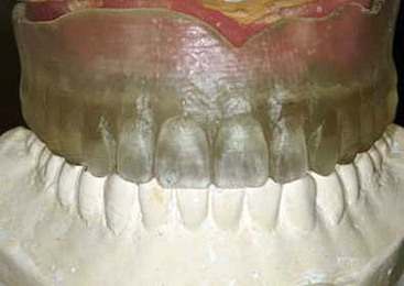
FIGURE 10-39 The patient’s duplicated denture is used to mount the master model against the apposing cast.
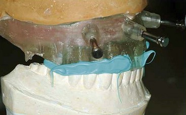
The third step involves fabrication of the surgical bite registration. The duplicated denture is removed from the mounted master cast and replaced by the surgical template. The surgical template and the mounted master cast are secured to each other using three fixation pins. Polyvinylsiloxane registration material is used to fabricate the surgical bite registration, which will further aid accurate orientation of the surgical template to the patient (Figure 10-40).
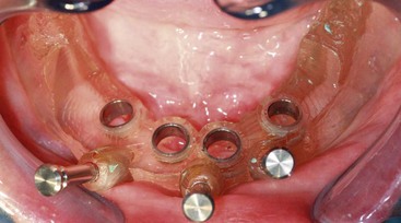
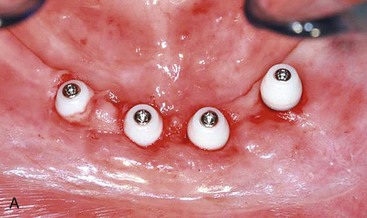
The fourth step is abutment selection. In cases in which axial implants have been placed, guided abutments have been used (Figure 10-41). Once the provisional prosthesis is fabricated, it is secured to the patient with six guided abutments (Figure 10-42).
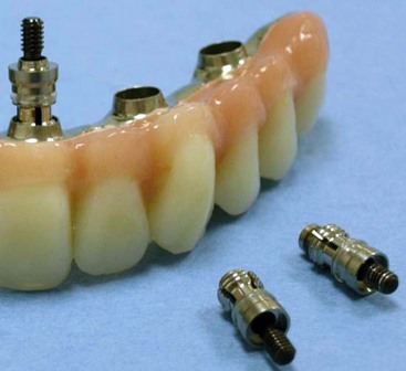
FIGURE 10-41 Completed computer-guided immediate-load prosthesis using the computer-guided abutment protocol.
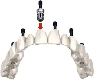
FIGURE 10-42 The computer-guided immediate-load prosthesis is secured to the patient using six computer-guided abutments.
(Courtesy Nobel Biocare, Yorba Linda, Calif.)
For the all-on-4 protocol, the anterior implants are axially placed and generally receive straight multiunit abutments (Figure 10-43). The two distal implants are tilted up to a maximum tilt of 45° to establish the greatest anterior-posterior spread8 with the premaxillary implants. Special non-hexed, 30° angulated multiunit abutments are used to bring the working platform of the tilted implants into the same occlusal plane as the axially placed anterior abutments (Figure 10-44). It is important to be aware that the 30° abutments used in the all-on-4 NobelGuide protocol are “non-hexed.” To transfer and duplicate the exact orientation of the non-hexed abutments from the master model to the patient, a “jig” is fabricated.
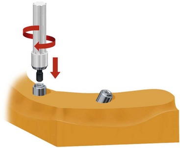
FIGURE 10-43 Straight multiunit abutments are used for the anterior implants in the All-on-4 protocol.
(Courtesy Nobel Biocare, Yorba Linda, Calif.)
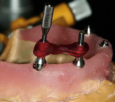
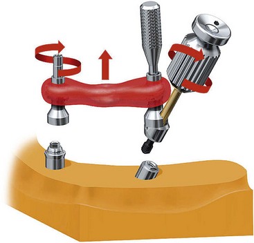
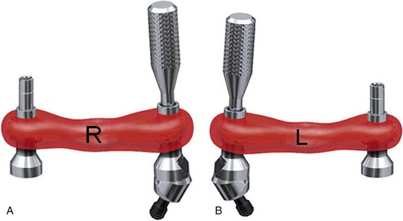
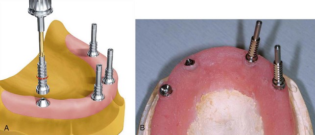
To begin fabrication of the jig, open-tray impression copings are secured to the straight multiunit abutments on the anterior implants (Figure 10-45). The non-hexed 30° degree abutments are placed on the posterior implants and receive modified open-tray impression copings (Figure 10-46). Using laboratory resin material, the ipsilateral anterior and posterior copings are luted together to secure the orientation of the abutments to each other (Figure 10-47). After ensuring that the luting material has completely cured (Figure 10-48), the retaining screw of the impression coping on the anterior implant is removed, leaving the multiunit abutment on the cast. On the posterior implant, only the 30°, non-hexed abutment screw is removed, maintaining the orientation of the 30° abutment with the modified open-tray impression coping (Figure 10-49). It is helpful to label each jig with an R and an L (Figure 10-50), signifying right and left, to prevent confusion during surgery. Once the jigs are fabricated and labeled, they are unscrewed from their associated abutments and removed from the master model. To facilitate the fabrication process of the provisional prosthesis, multiunit titanium temporary cylinders are secured to the abutments (Figure 10-51, A), and the laboratory technician can begin fabrication of the provisional prosthesis (Figure 10-51, B).
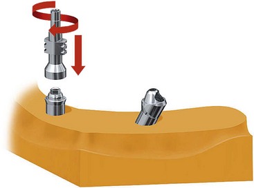
FIGURE 10-45 Closed-tray multiunit impression copings are secured to the anterior implants, initiating the fabrication of the jig.
(Courtesy Nobel Biocare, Yorba Linda, Calif.)
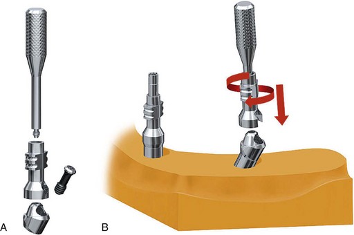
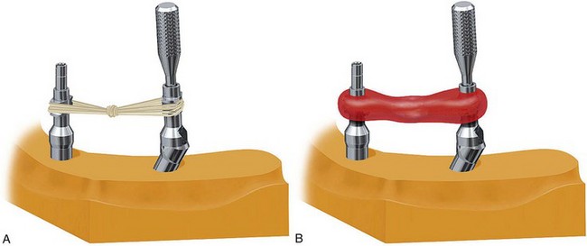
FIGURE 10-47 Dental floss is used to link the anterior impression coping to the posterior impression coping.
(Courtesy Nobel Biocare, Yorba Linda, Calif.)
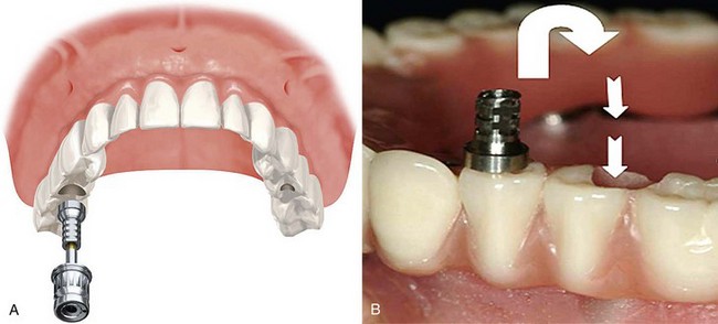
Once the all-acrylic provisional prosthesis is fabricated, to further aid in a passive seat of the provisional prosthesis immediately following implant placement, the laboratory technician trephines at least one or preferably two of the temporary cylinders out of the all-acrylic prosthesis.5 The remaining cylinders, which are incorporated within the prosthesis, allow proper orientation of the prosthesis to the patient. After completion of the surgery and during delivery of the prosthesis, the trephined cylinders are secured to the abutments and luted intraorally to the prosthesis in an attempt to maximize potential for a passive fit (Figure 10-52). The same type of jig is fabricated for use with tilted treatment concept in mandibular cases.
The final step of the laboratory phase includes removal of the fabricated provisional prosthesis (Figure 10-53) from the master cast and packing the jigs ready for surgery. After the prosthesis is removed from the master model, the fabricated jigs are screwed back onto the abutments, which are still secured to the master model. First, the abutment screw of the 30° abutment is loosened and removed. This leaves the 30° abutment securely attached to its impression coping. Then the open-tray impression coping screw of the anterior implant abutment is removed. The “jig” at this point is composed of the open-tray impression coping anteriorly and the modified open-tray impression coping secured to the 30° abutment posteriorly. The jigs are packed carefully to prevent breakage. The straight multiunit abutments are now removed from the anterior implants and packaged separately.

Stay updated, free dental videos. Join our Telegram channel
VIDEdental - Online dental courses


