Fig. 3.1
Percentage of treatment plans changed by each of the three examiners after reviewing the CBCT
3.2 Implications for Clinical Practice
Under the conditions of the previous study [24], CBCT was a more accurate imaging modality for diagnosis of tooth anatomy and periradicular pathosis when compared to diagnosis using only periapical radiographs. An accurate diagnosis was reached in 36.6–40 % of the cases when using periapical radiographs compared to an accurate diagnosis in 76.6–83.3 % of the cases when using CBCT (Fig. 3.2). This high level of misdiagnosis is potentially clinically relevant, especially in cases of invasive cervical root resorption and vertical root fracture where a lack of early detection could lead to unsuccessful treatment and tooth loss. The previous study also demonstrates that the treatment plan may be directly influenced by information gained from a CBCT scan as the examiners altered their treatment plan after viewing the CBCT scan in 62.2 % of the cases overall (range from 56.6 to 66.7 %). This high number indicates that CBCT had a significant influence on the examiners’ treatment plan.
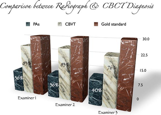
Fig. 3.2
Comparison between diagnosis after viewing a periapical radiograph vs. diagnosis after viewing CBCT for examiners 1, 2, and 3
It can be concluded that a preoperative CBCT scan provides more diagnostic information than a preoperative periapical radiograph and that this information can directly influence a clinician’s treatment plan. Although imaging is a very important diagnostic tool in endodontics, it should always be used as an adjunct to the clinical exam. The addition of subjective and objective clinical findings to CBCT should allow for an even more accurate clinical diagnosis and appropriate treatment plan. Future studies may explore the potential added value of CBCT when provided along with relevant history and clinical findings.
3.3 Conclusion
Cone beam computed tomography overcomes many of the limitations of periapical radiography. The increased diagnostic information provided by the CBCT scan should result in more accurate diagnosis and improved decision-making for the management of complex endodontic problems. CBCT is a desirable addition to the endodontist’s armamentarium. Examples of cases where CBCT made a significant difference in the treatment planning process are presented in Figs. 3.3, 3.4, 3.5, 3.6, 3.7, 3.8, 3.9, 3.10, 3.11, 3.12, 3.13, 3.14, 3.15, and 3.16.

Fig. 3.3
(a) Periapical radiograph of tooth #2. The patient was referred for nonsurgical root canal treatment with a diagnosis of pulp necrosis and asymptomatic apical periodontitis. (b) Sagittal view showing the distobuccal root fracture. (c) Coronal view showing the unusual horizontal fracture of the distobuccal root. (d) Axial view of the apical one third showing a vertical buccopalatal root fracture. (e) 3D reconstruction showing the extent of the distobuccal root fracture
Fig. 3.4
Patient was referred for evaluation of pain to biting related to tooth #12. (a) Tooth # 12 had previous root canal treatment. Periodontal probing depths were WNL. The two lines correspond to the axial section views in (b and c). (c) demonstrates buccal loss of bone mid-root which is a pattern of bone loss (blue arrow) that is suggestive of VRF. (d) Coronal view of tooth #12 demonstrating mid-root buccal bone loss (black arrow). The intact collar of marginal bone has a tight periodontal fiber attachment, which explains why many roots with VRF do not probe in the early stages. (e) 3D reconstruction demonstrating the intact marginal bone and loss of buccal bone (black arrow). The buccal bone loss is usually adjacent to the VRF site
Fig. 3.5
Continuation of case in Fig. 3.4: (a) Tooth #12 after surgical extraction. The black arrows are the VRF which corresponds to the area of buccal bone loss in the CBCT. (b) An immediate implant was placed after the extraction. (c) Temporary restoration in place without loading the implant
Fig. 3.6
(a) Periapical radiograph of tooth #14. Symptoms included spontaneous pain and abnormal sensitivity to cold. After clinical examination and testing, the diagnosis was symptomatic irreversible pulpitis with symptomatic apical periodontitis. (b) CBCT sagittal view of tooth #14 showing an invasive cervical resorptive defect (ICR – Heithersay Class IV) that cannot be detected on the periapical radiograph. (c) Axial view demonstrating the palatal and mesial location of the defect. (d) Coronal view demonstrating the internal aspect of the ICR defect, rendering tooth #14 non-restorable. A change in treatment plan was made and the patient was referred for extraction
Fig. 3.7
(a) Periapical radiograph of tooth #6. The patient was referred for evaluation and treatment of an internal resorptive defect. The line corresponds to the axial section view in (d). (b) 3D reconstruction of the resorptive defect (black arrow). (c) Sagittal view of tooth #6 demonstrating the internal resorptive defect (red arrow), and confirming that the defect is an external ICR defect with initial entry at the cemento-enamel junction (yellow arrow). (d) Axial view demonstrating the ICR nature of the defect. Note in (c, d) that the pulp was not involved. (e) Postoperative radiograph of tooth #6 after root canal therapy and repair of the resorptive defect
Fig. 3.8
(a) Periapical radiograph of tooth #21. The patient was referred for evaluation and treatment of an internal resorptive defect. The line corresponds to the axial section view in (b). (b) Axial view demonstrating the ICR nature of the defect (yellow arrow). (c) 3D reconstruction of the resorptive defect (black arrow). (d) Coronal view of tooth #21 demonstrating the external/internal resorptive defect (blue arrow). Note in (b, c, and d) the perforated root on the buccal aspect renders tooth #21 non-restorable. The treatment plan changed after reviewing the CBCT images
Fig. 3.9


(a) Periapical radiograph of teeth #7 and 8. Treatment was initiated on both teeth before referral to an endodontist. (b) Clinical picture showing normal soft tissue color and architecture. (c, d) are sagittal CBCT images showing facial perforations on teeth #7 and 8, respectively
Stay updated, free dental videos. Join our Telegram channel
VIDEdental - Online dental courses
