Implant Restoration of the Mandibular Edentulous Patient
Steven J. Sadowsky
University of the Pacific Arthur A. Dugoni School of Dentistry, San Francisco, California, USA
In 2009, the British Society for the Study of Prosthetic Dentistry met in York, UK to follow up the McGill Consensus of 2002 on the most appropriate restoration of the edentulous mandible.1,2 The York statement concluded that there is a substantial body of evidence of high rigor with patient‐centered outcomes to demonstrate that the two‐implant overdenture, while not the gold standard of implant therapy, is the minimum prosthetic modality that should be rendered to this class of patients. This statement, in conjunction with Fitzpatrick’s treatise3 on the standard of care for the edentulous mandible, underscores the fact that there is no single universally superior treatment for the edentulous mandible. In fact, patient acceptance of specific implant treatment designs is predicated on a multiplicity of factors, such as educational background, cultural/regional influences, age, and socioeconomic influences. Therefore, the decision to restore the edentulous mandible with either an implant overdenture (IOD), an implant fixed complete denture (IFCD), or fixed dental prosthesis (FDP) requires an in‐depth analysis of patient‐mediated factors and also systemic and local considerations for a cohort that is not quite becoming an endangered species.
Incidence of edentulism and demographic trends on implant treatment acceptance
Across a 5‐decade observation period, edentulous prevalence has declined from 18.9% in the mid‐1950s to 4.9% in 2010 (12.2 million patients), and is projected to be 2.6% by 2050 (6.8 million patients) in the US.4 With its highest incidence in states with disproportionately high poverty, edentulism is a rare condition in high‐income households. Thus, those most affected by this debilitation may be the least able to afford implant treatment modalities. This is in spite of the fact that higher initial fees for an implant‐borne versus a conventional prosthesis are compensated by cost effectiveness, especially given longer life expectancies.5 The prospect for more affordable implant treatment has been fueled by the number of implant companies offering competitive pricing and the expansion of delivery of implant rehabilitative care across the spectrum of practitioners.6 However, compounding the present economic barrier is the lack of knowledge about implants in the geriatric cohort. Promotion of oral health with an emphasis on implant therapy education would address concerns about suitability, morbidity, and quality‐of‐life improvement.7 When patients are in good health and live independently, regardless of the age, dental implant therapy offers a sustained benefit.8
Systemic factors
There is an established association between edentulism and advancing age.9 A number of studies have addressed the impact of implant placement in the geriatric cohort.10–12 Engfors et al.13 compared patients older and younger than 79 years treated with mandibular implant fixed complete dentures (IFCD) and, after 5 years, implant survival was above 99% for each group. Notwithstanding these results, 10% of older patients have difficulties with adaptation and muscle control with implant prostheses.14 While old age is not a contraindication, patients over 65 years of age should receive an in‐depth evaluation because of potential medical complications and psychosocial considerations. Absolute contraindications to implant placement include recent myocardial infarction, recent cerebrovascular accident, uncontrolled diabetes, intravenous use of bisphosphonates, severe immunocompromise, irreversible bleeding dyscrasias, alcohol/drug addiction, and significant psychiatric disorders or unrealistic expectations.15,16 While individual relative contraindications do not preclude implant placement, combinations of chronic disease states have been implicated in cluster failures of implants.17,18 A recent systematic review reported a positive association between multimorbidity and age and lower socioeconomic status.19 There is a number of specific disorders that have their onset later in life.
Osteoporosis affects 16% of women and 4% of men in the femur neck or lumbar spine after the age of 50.20 There is no evidence of high rigor that dental implants in osteoporotic patients have a higher failure rate.21 Moreover, the anterior mandible has not been reported to suffer an age‐related osteopenia.22 The influence of oral bisphosphonate (alendronate) use for osteoporosis on dental implant survival was recently evaluated in a multicentered prospective study, including completely edentulous patients.23 After a 6‐month cessation of drug treatment, the use of preoperative antibiotic prophylaxis, and 4‐month healing time, no implant failures resulted.
Menopause has been associated with increased bone resorption. While nonestrogen replacement postmenopausal women have been reported to have lower implant survival in the maxilla (13.6%), no significant differences were noted on the mandible.24
Other relative contraindications not necessarily related to the aging population, such as smoking, use of antidepressants, steroid medications, controlled diabetes, or therapeutic ionizing radiation, need to be assessed in concert with a complete medical/dental work‐up.16,18,25,26
Local factors
As only a small percentage of patients are precluded from implant therapy because of systemic factors, clinician‐ and patient‐mediated considerations become an important gate for predicting implant success, not just survival. It is essential that the practitioner make an assessment of hard and soft tissue status, arch form, jaw classification, applied forces, antagonist dentition, and interarch space allowance, which may predicate the decision regarding implant number, position, anchorage system, and restorative superstructure design and material on the edentulous mandible.
The advent of low‐radiation, low‐cost cone‐beam computed tomography (CBCT) and illustrative software has enabled the implant team to assess three‐dimensionally the bony foundation for implant placement. This affords a cross‐sectional view which may unveil otherwise undetected hourglass bone (Figure 18.1a) (3.89% incidence)27 and/or posterior lingual concavities (Figure 18.1b) (estimation of lingual plate perforation 1.1–1.2%),28 which increase the risk of surgical complications.
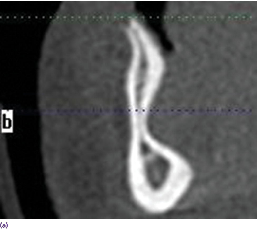
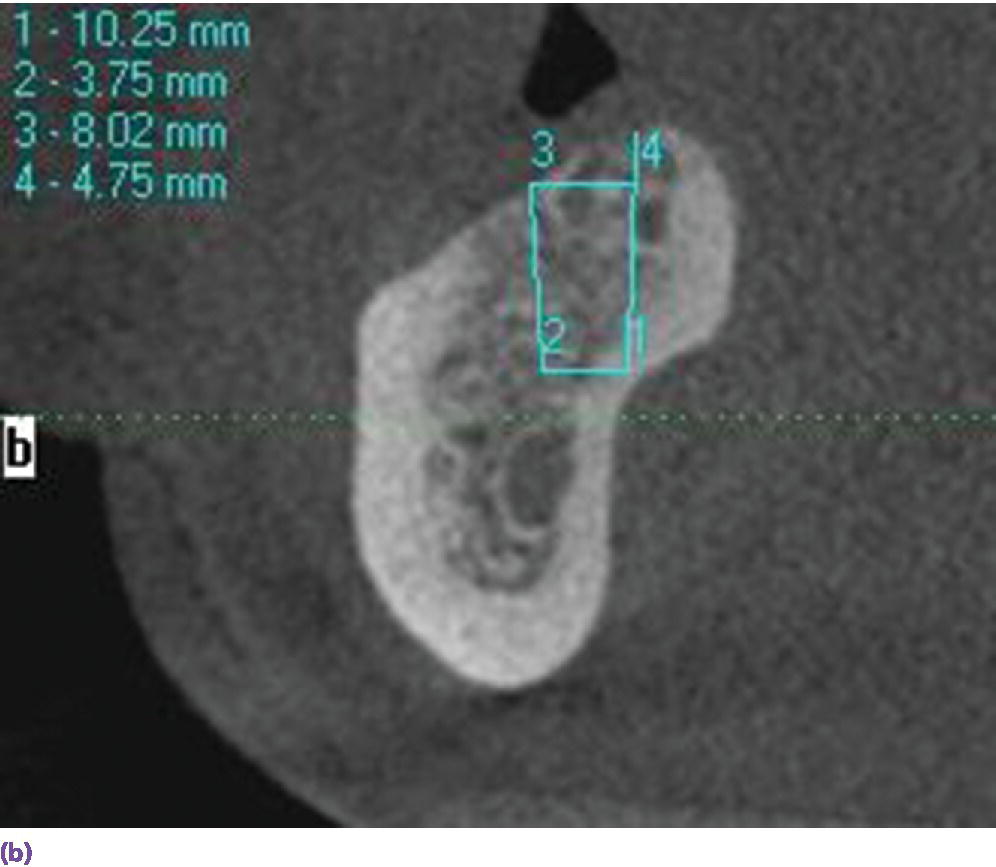
Figure 18.1 (a) Hourglass morphology of anterior mandibular bone as seen on CBCT. (b) Mandibular lingual concavity as seen on CBCT.
When an overdenture is planned for a V‐shaped arch, a two‐implant design potentiates rotational movement in the sagittal plane (Figure 18.2a), while a three‐implant tripod resists it (Figure 18.2b). The cantilever of the IFCD design was historically limited by the anterior–posterior (AP) span of the implants and, if square arch forms were restored with this modality, the occlusal table was shortened, before the advent of tilted implants (Figure 18.3).
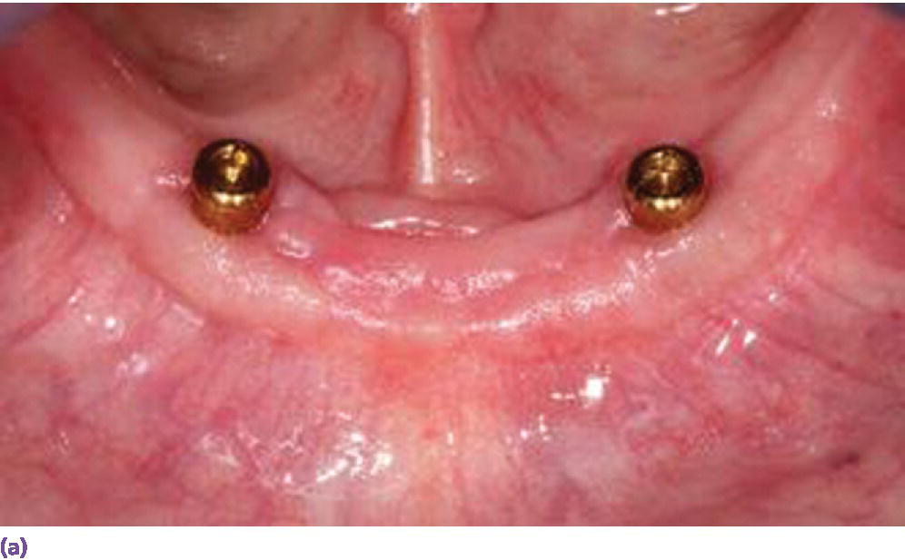
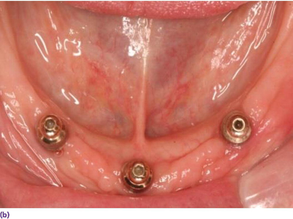
Figure 18.2 (a) U‐shaped arch restored with two solitary anchors which may demonstrate anterior–posterior rotation on incisal biting. (b) V‐shaped arch managed with three implants to resist anterior lever arm.
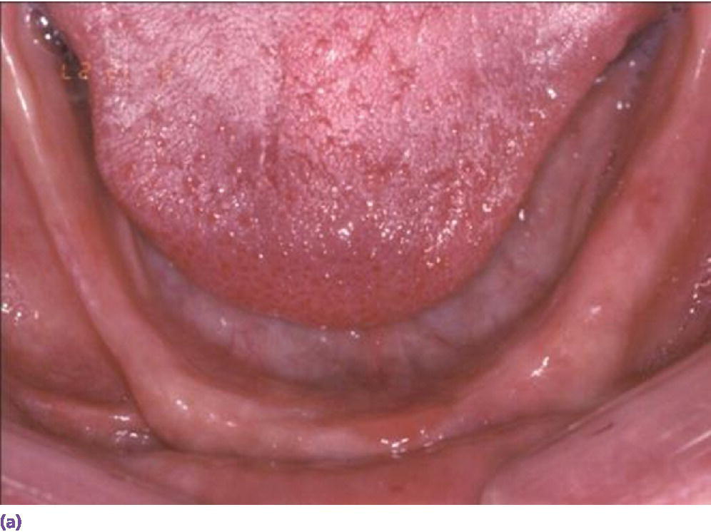
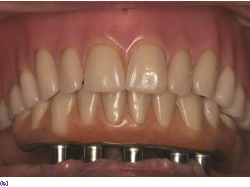
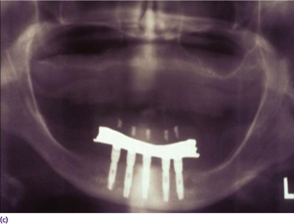
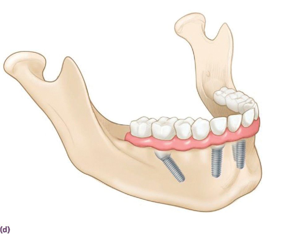
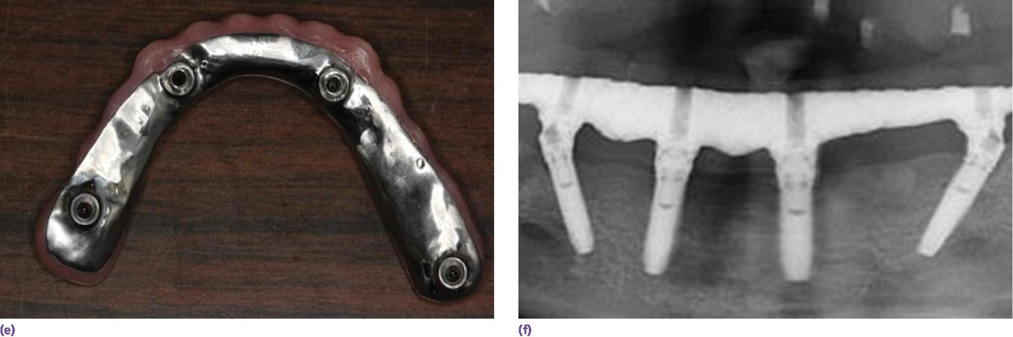
Figure 18.3 (a) Square‐shaped arch with limited projected anterior–posterior (AP) span for vertically placed implants. (b) Limited cantilever extension for implant fixed complete denture due to minimal AP span generated by vertically placed implants and adhering to formula (cantilever = 1.5AP span). (c) Radiographic depiction of shortened cantilever IFCD. (d) Graphic illustrating the extended occlusal table and reduced cantilever afforded by tilted terminal implants. (e) Square arch reconciled by tilted implants. (f) Radiographic depiction of All‐on‐4 prosthesis in (e).
Source: © 2016, Chris Gralapp.
Class II overdenture patients may be best treated with an anchorage system that includes distal extension retentive units to stabilize the preferential posterior loading (Figure 18.4). However, caution should be used when fabricating cantilever extensions without robust connectors to the primary bar, as a high fracture incidence has been reported.29
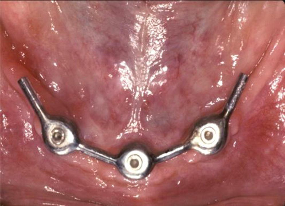
Figure 18.4 Cantilever extension implant overdenture anchorage system designed to improve stability with class II patients, improve retention with intransigent gaggers, or/and protect sensitive mucosa over mental foramina region.
Parafunction and/or antagonist natural dentition may dictate additional implant support to resist increased stresses (Figure 18.5a).30–32 Four to seven times the maximum bite force has been quantified in bruxers.33 An opposing natural dentition may be difficult to equilibrate for a harmonious occlusal scheme, which may potentiate preferential loading (Figure 18.5b, c).34
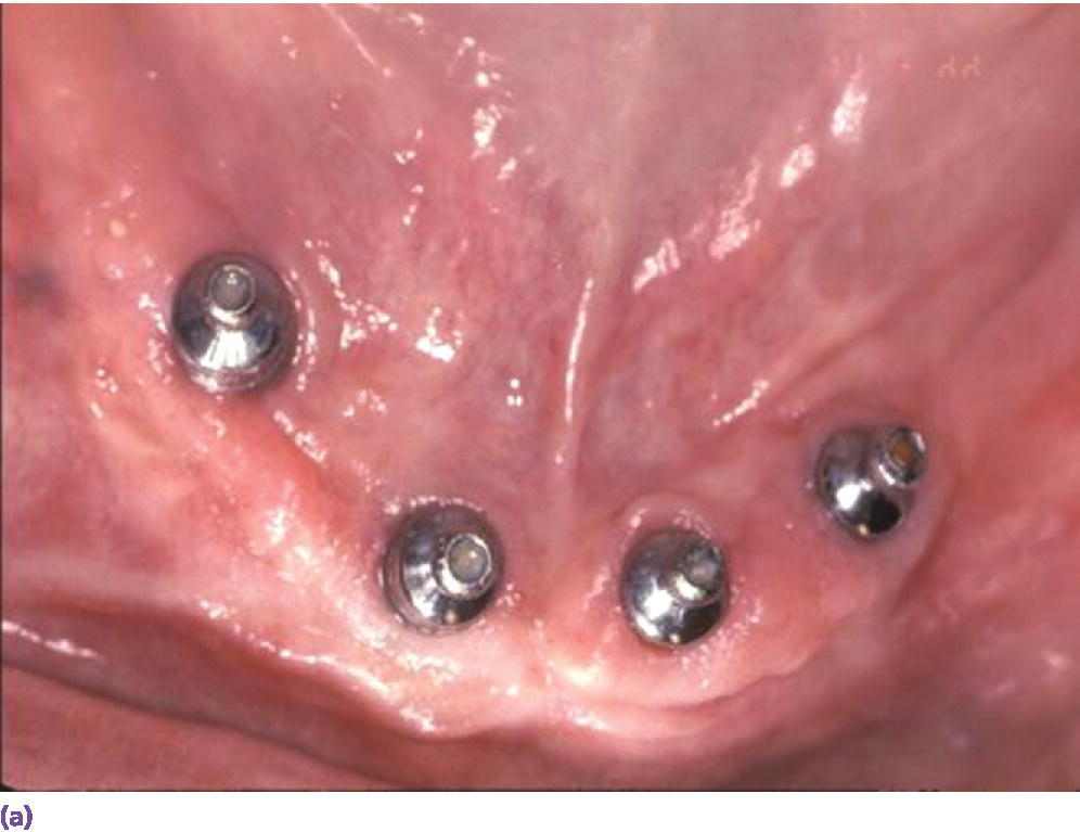
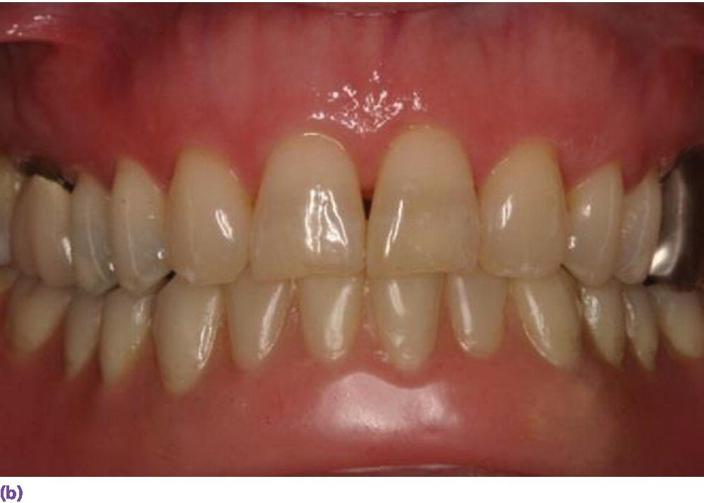
Figure 18.5 (a) Multiple implants placed in edentulous mandible opposing a natural dentition. (b) Frontal view of mandibular implant overdenture opposing natural dentition. (c) Occlusal view of mandibular implant overdenture opposing natural dentition.
Space allowance varies with prosthetic design.35,36 An overdenture retained by Locator® abutments (Zest Anchors LLC, Escondido, CA) (Figure 18.6a), resilient Dolder bar (Figure 18.6b), or spark‐eroded milled bar (Figure 18.6c, d) requires 8–9 mm, 12 mm, and 12–15 mm, respectively, from the crest of the tissue to the incisal/occlusal table. An IFCD (Figure 18.6e) will require 12–15 mm and an IFDP (Figure 18.6f, g) may need 7 mm interarch space on the mandible.37 A mounted resilient cast technique is helpful to visually assess the interarch space available, if the patient has been restored with an equilibrated mandibular complete denture. In preparation, the vertical dimension of occlusion must be verified by subtracting 3 mm from the vertical dimension of rest (class I scenario) along with adequate speaking space and esthetic evaluation. In an edentulous patient, the maxillary denture is mounted on an articulator with a facebow or facial analyzer (Kois Dento‐Facial Analyzer, Panadent Corporation, Colton, CA) (Figure 18.7a) after laboratory putty (Splash Putty, DenMat, Lompoc CA) is placed in the intaglio surface of the denture and reinforced for mounting with paperclips (Figure 18.7b). The mandibular denture is prepared similarly with laboratory putty in the intaglio aspect and hand articulated to the maxillary denture, affixed with glue sticks. After mounting is complete, a vertical space analysis can be accomplished when the denture is removed from the resilient cast (Figure 18.7c–e). If the existing mandibular denture is satisfactory, for the vertical dimension of occlusion, occlusal and esthetic harmony, and fit, it may be used as a blueprint for a radiographic template. Otherwise a new wax try‐in is required. In either case, the use of the Denture Duplicator Kit (Lang Dental Mfg Co Inc., Wheeling, IL) facilitates fabrication of a radiographic/surgical template. The former will require a ratio of 4:1 clear orthodontic resin (Caulk Orthodontic Resin, Dentsply, York, PA) to barium sulfate (Barium Sulfate, Henry Schein, San Francisco) for the tooth forms (Figure 18.7f–h).
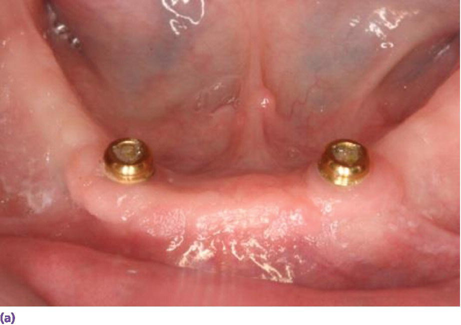
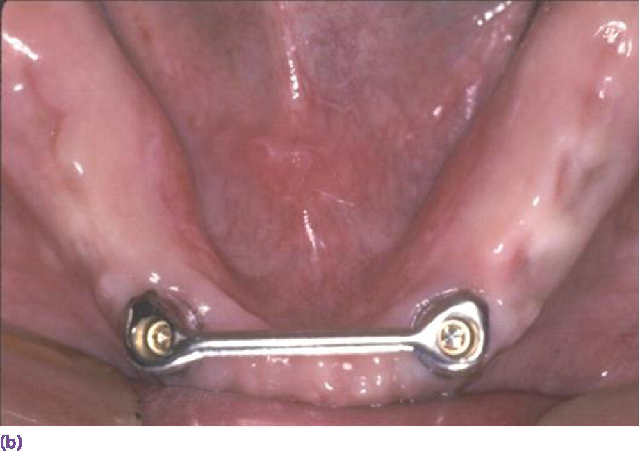
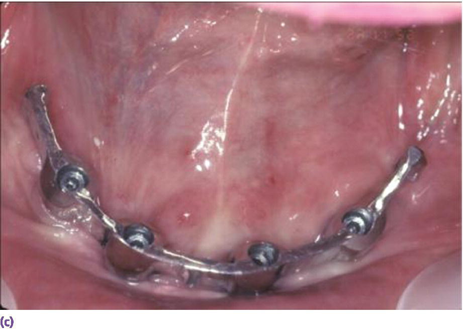
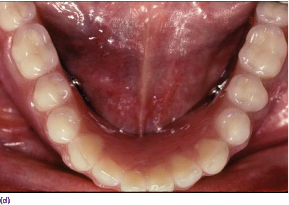
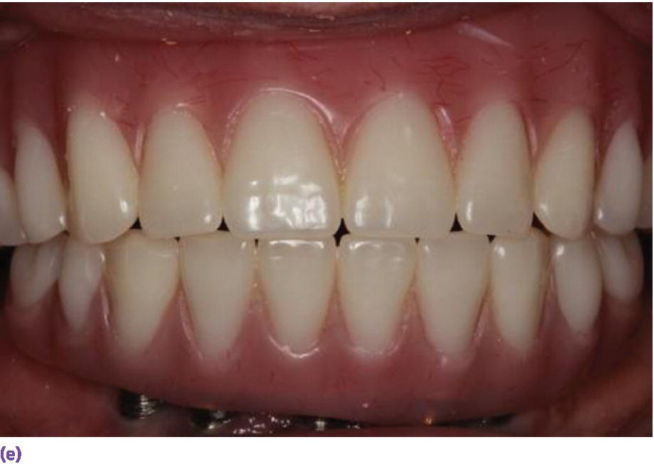
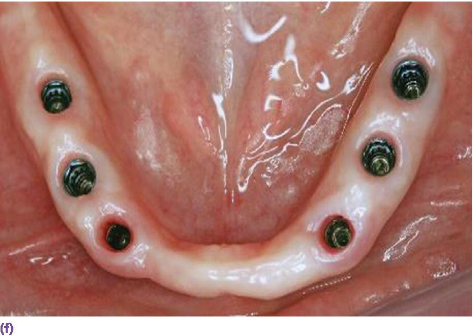
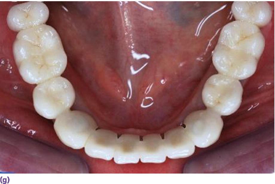
Figure 18.6 (a) Locator® anchorage system requiring ≥8 mm of interarch space from crest of soft tissue to opposing dentition. (b) Dolder bar anchorage system requiring 12 mm of interarch space from crest of soft tissue to opposing dentition. (c) Spark‐eroded 2‐degree milled bar anchorage system requiring ≥12 mm of interarch space from crest of soft tissue to opposing dentition. (d) Cameo view of suprastructure of milled bar overdenture. (e) Implant fixed complete denture requiring ≥12 mm of interarch space from crest of soft tissue to opposing dentition. (f) Limited resorption of ridge allowing for a porcelain‐fused‐to‐metal design (implant fixed dental prosthesis). Placement of implants is critical to be congruent with restorative design. (g) Porcelain‐fused‐to‐metal implant reconstruction requiring 8–10 mm of interarch space.
Source for (f, g): Reproduced with permission from Charles Goodacre.
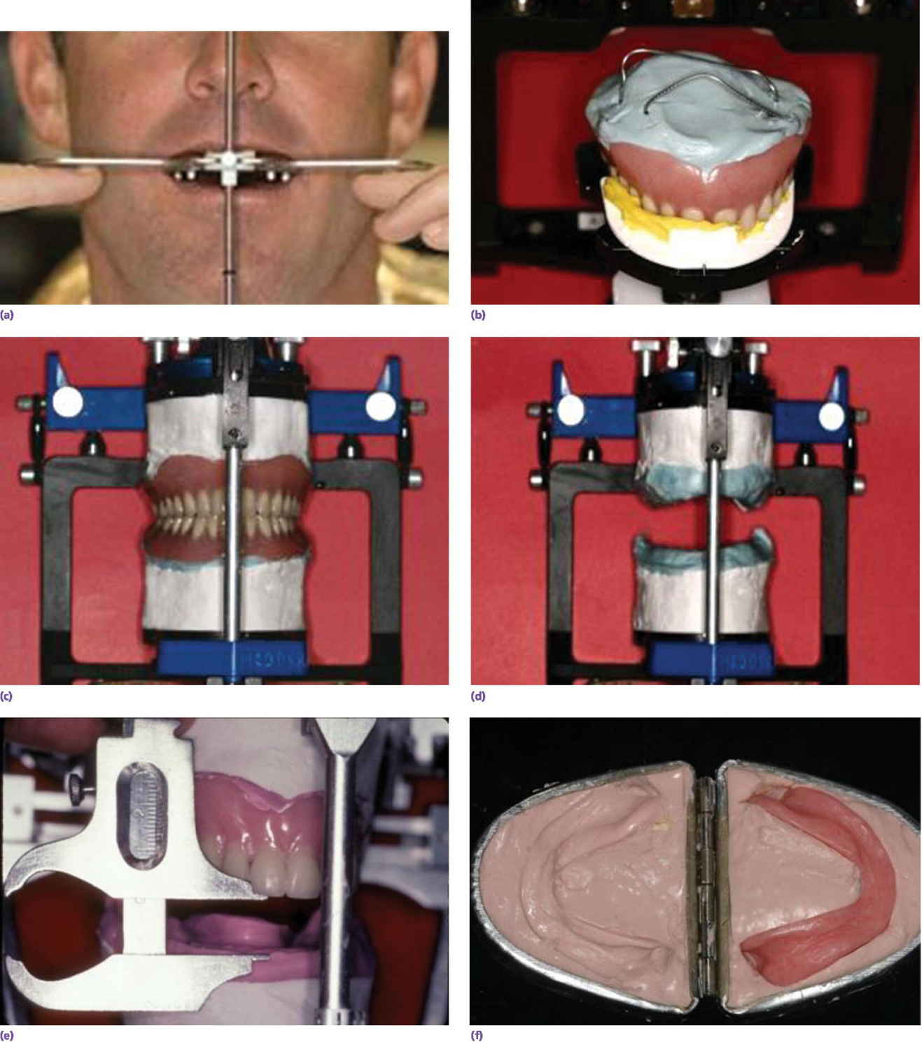
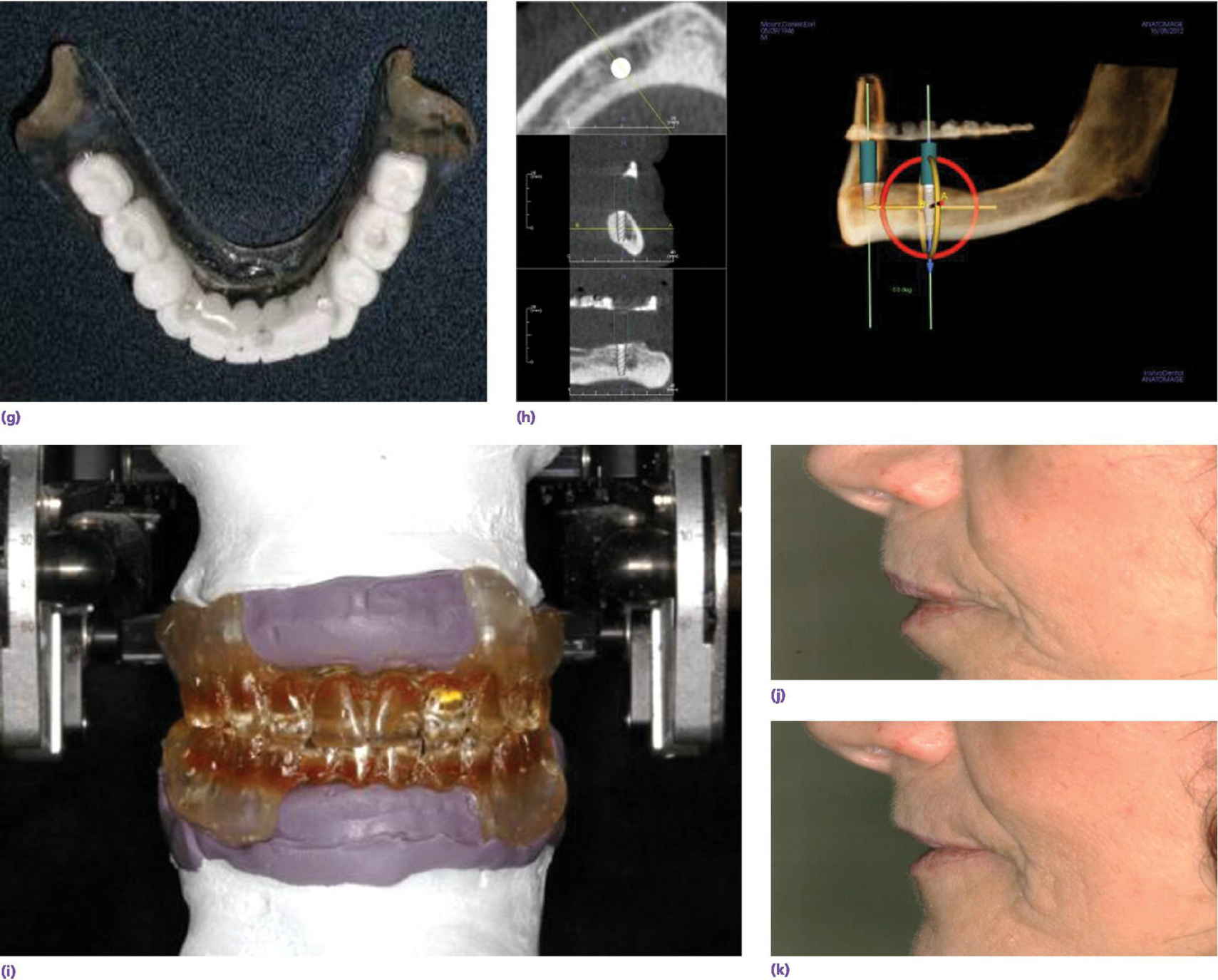
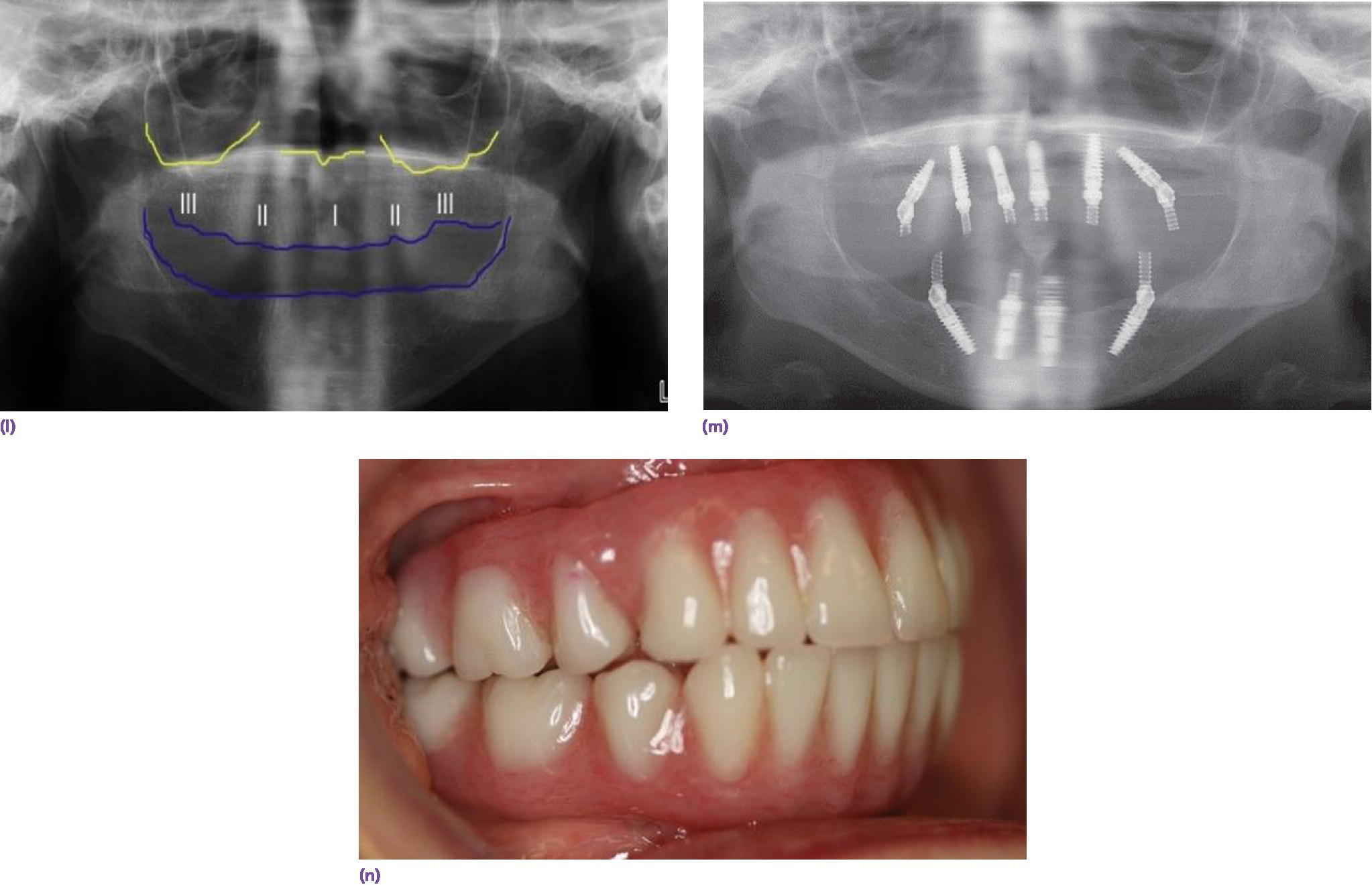
Figure 18.7 (a) Kois Facial Analyzer in place to transfer, three‐dimensionally, the position of the maxillary denture to the articulator. (b) Maxillary denture positioned on mounting stand via registration material. The intaglio surface of the denture is filled with laboratory putty and paper clips are engaged in the putty to provide retention for mounting stone. (c) The maxillary denture is mounted on the articulator and the mandibular denture is hand articulated to it (given vertical and horizontal records are appropriate). The intaglio surface of the mandibular denture is filled with laboratory putty and reinforced with paper clips in preparation for mounting on the articulator. (d) Dentures are removed to reveal mounted resilient casts. (e) Vertical measurement determined between occlusal aspect of maxillary denture and mandibular ridge crest. (f) Lang Denture Duplicator with alginate, used to create a replica of existing denture or ideal wax‐up for radiographic/surgical template. (g) Radiographic/surgical template. (h) CBCT scan with software program orienting the implants in three dimensions with radiographic template in place for a two‐implant overdenture design. (i) Duplicate dentures with anterior flanges removed. (j) Profile of patient with complete dentures in place, demonstrating excessive lip support from anterior flanges. (k) Profile of patient with flangeless duplicates of dentures in place demonstrating natural lip contours. (l) Preoperative evaluation of orthopantomogram for available bone for implant placement. Need for alveoplasty was dictated by the resilient cast measurement. (m) Implant placement after alveoplasty. (n) Definitive implant fixed complete dentures in place.
Duplication of the dentures without the anterior flange may also be needed to assess the importance of mimicking the same facial scaffolding (Figure 18.7i). The patient is seen with her dentures in place (Figure 18.7j). The nasolabial and the labiomental angles are too acute, revealing excessive lip support. With the flangeless dentures in place, the facial anatomy is restored (Figure 18.7k). Therefore, an IFCD would be esthetically acceptable. Once the analysis is complete, determination of available bone, requirement for alveoplasty, and planning for implant position can commence to satisfy the clinician‐ and patient‐mediated factors (Figure 18.7l–n).
When a patient presents with a terminal dentition (Figure 18.8a), the use of digital workflow software allows implant placement planning, along with the fabrication of sequenced stereolithographic templates (Figure 18.8b–e). The teeth assist in orienting the cross‐pins that will standardize the position of all the templates in three dimensions (Figure 18.8f). The second template is placed after extractions to guide the alveoplasty (Figure 18.8g). The third template will guide the implant placement (Figure 18.8h). This allows for either an immediate‐ or delayed‐loading protocol (Figure 18.8i, j).
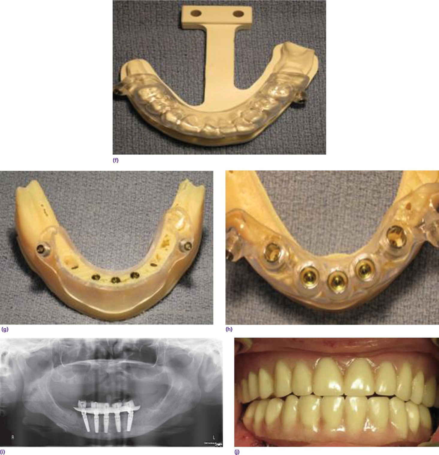
Figure 18.8 (a) Preoperative orthopantomogram of edentulous maxilla and terminal mandibular dentition. (b) CBCT scan displaying potential sites for implants using software program. (c) CBCT scan of implant positions using three anterior vertical implants and two tilted terminal implants. (d) 3‐D rendering of preoperative mandible with two cross pins established for referencing templates. (e) Virtual alveoplasty. (f) First template keyed to the existing dentition to orient osteotomy for cross pins. (g) Second template oriented by cross pins for alveoplasty. (h) Third template oriented by cross pins for implant placement. (i) Orthopantomogram of implant placement and immediate provisional prosthesis. (j) Definitive prostheses.
Source: Courtesy of Fawas Alzoubi; reproduced with permission.
Patient‐mediated factors
Patient preferences in the final analysis may dictate treatment, given that the implant rehabilitation meets sound prosthodontic principles. These include cost, treatment time, maintenance considerations, and fixed versus removable designs.38 Implant overdentures (IOD) are either implant supported (ISOD) or implant‐retained and tissue‐assisted (IROD). Mean incremental costs of a two‐implant retained overdenture (IROD) and a four‐implant supported overdenture (ISOD) were compared to a complete denture.39 The ISOD was found to be three times the initial cost of the IROD, but with modest improvement in chewing ability. When ISODs were compared to IFCDs in long‐term studies, the initial cost, maintenance, and clinical time were significantly higher with the IFCDs.40,41 Comparative long‐term cost analysis of metal–ceramic implant restorations for the edentulous mandible is lacking in the literature. Contrary to conventional wisdom, cross‐over studies and psychometric analyses have failed to demonstrate significant differences in patient satisfaction between removable (implant retained or supported) overdentures and IFCDs.42,43 Patients over 50 years old, experienced denture users, and those with hygiene accessibility priorities favored a removable implant prosthesis.
The implant overdenture versus a conventional denture
When comparing patient satisfaction and oral health‐related quality‐of‐life (QOL) outcomes before and after implants are placed and restored in the edentulous mandible, a number of studies with up to a 10‐year follow‐up demonstrates advantages of the IROD versus the CD in chewing ability, stability, and comfort, irrespective of mandibular bone height.44–48 Furthermore, when compared to a CD, the IROD was responsible for a greater self‐confidence and satisfaction in social interactions.49 While 51% of denture patients reported discomfort on chewing significantly impacting their diet,50 surprisingly, no improvement in nutritional status, body mass index, or serum albumin values has been reported with the IROD.51
Given that the annual mandibular bone loss in the edentulous patient averages 0.4 mm,52 it is of note that, after 12 years, only an average 1.7 mm of bone loss has been observed around implants retaining a hinging overdenture.53 Similar long‐term peri‐implant outcomes in two‐implant overdenture patients have been documented, with splinted or nonsplinted anchorage systems or different loading protocols.54–56 However, the two‐implant IROD has not been found to be protective of posterior bone levels.57 In fact two to three times the bone resorption was reported after 2 years of IROD use as compared to CD use.58 Considering patient preferences, when patients have highly atrophied mandibular posterior alveolar bone and/or they are young, an IFCD would be preferable to an IROD.59
Number of implants, anchorage system, and maintenance of the implant overdenture
Number of implants
When comparing two‐ and four‐implant designs with at least a 5‐year follow‐up, patient satisfaction or peri‐implant health were not influenced by the number or type of anchorage system (Figure 18.9a, b).31,60–62 However, the indication for more than two implants and type of anchorage system should be predicated on clinician‐ and patient‐related factors. For example, in patients with a dentate maxilla, narrow tapered arches, high muscle attachments, and sharp mylohyoid ridges, more than two implants are recommended for prosthetic stability.38,63 A recent 5‐year randomized clinical trial also discerned no statistically significant differences in patient satisfaction, implant survival, or maintenance with a one‐ or two‐implant mandibular overdenture modality (Figure 18.10).64 This alternative appears to be appropriate for septuagenarians and octogenarians with surgical morbidity and financial concerns. However, a metal‐reinforced prosthesis for the solitary anchor design was recommended to thwart a higher incidence of fracture in this design.
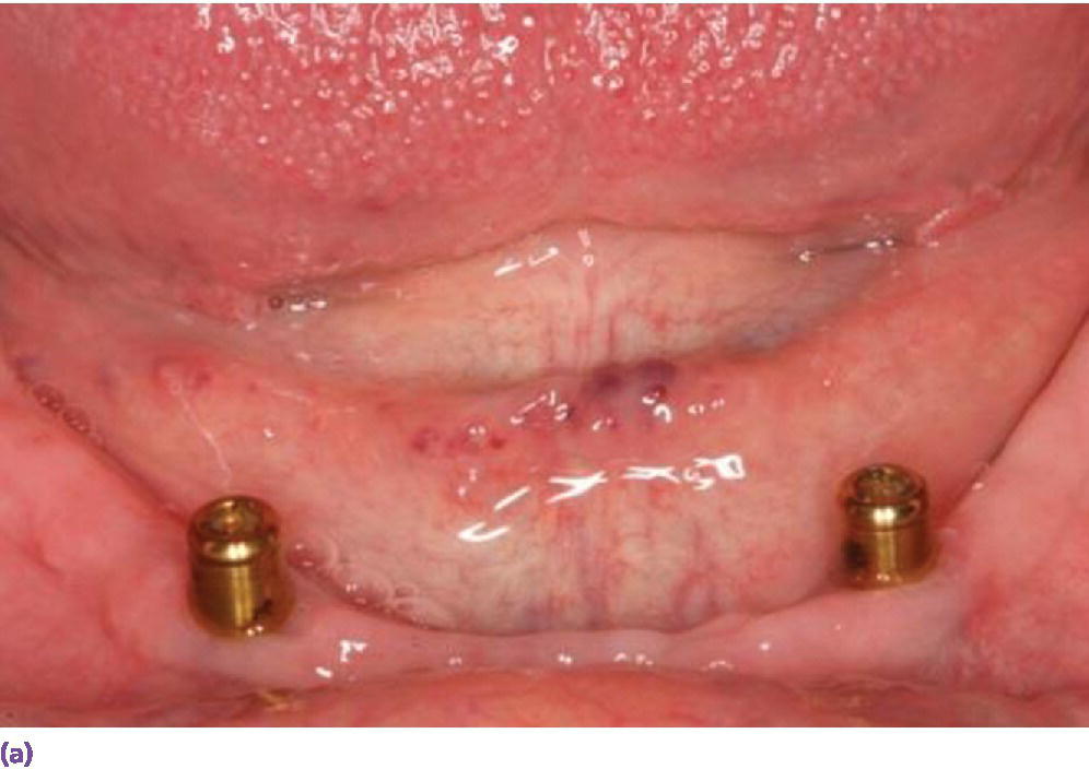
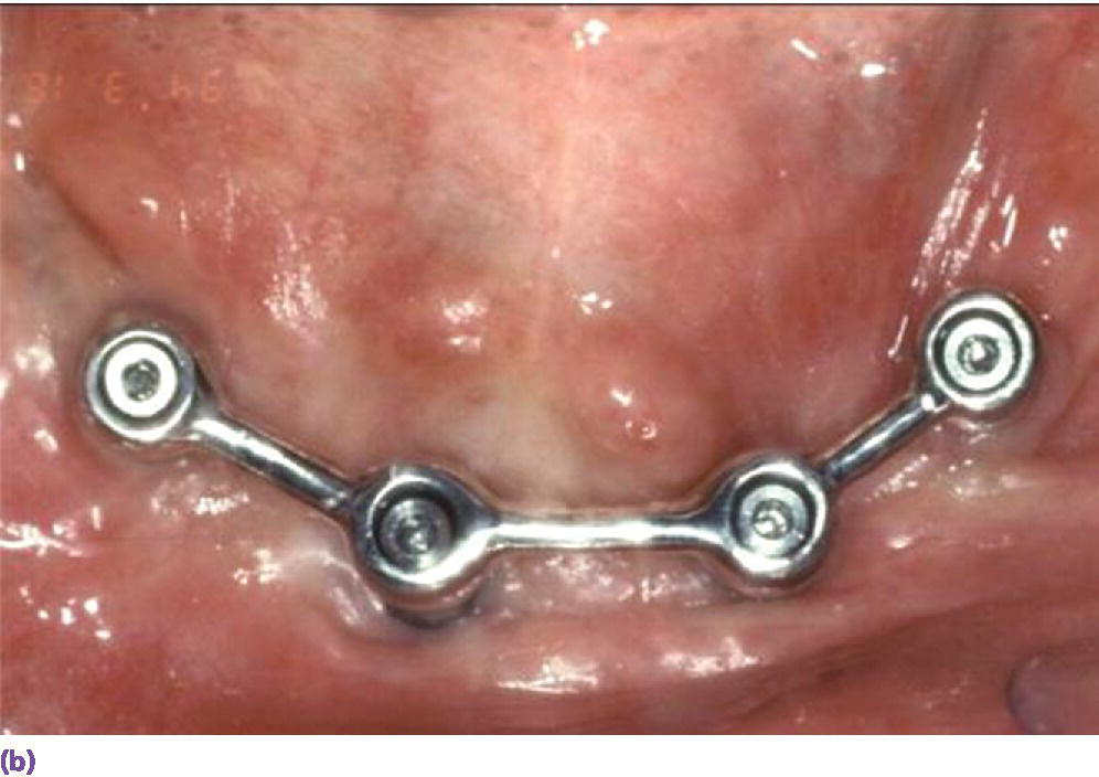
Figure 18.9 (a) Two‐implant solitary anchor design (Locator®) for overdenture. (b) Four‐implant splinted bar design for overdenture.
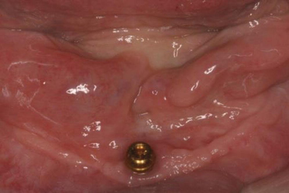
Figure 18.10 Single symphyseal design (Locator®) for overdenture.
Anchorage system
When considering splinted versus solitary anchors, local and patient‐mediated factors often prevail. A splinted bar with a distal extension is recommended for patients with sensitive mucosa over the superficial mental foramina area.38 Distal bars also provide additional retention for enhanced prosthetic stability when this feature is at a premium for the patient, such as in the intransigent gagger. When two implants are used to retain a bar with cantilever extensions, the distal bars should not extend beyond the first premolar position and together should be no longer than the central bar (Figure 18.11).63 On the other hand, solitary anchors are preferred in patients with lack of keratinized tissue, interarch space limitations, and hygiene or economic concerns.
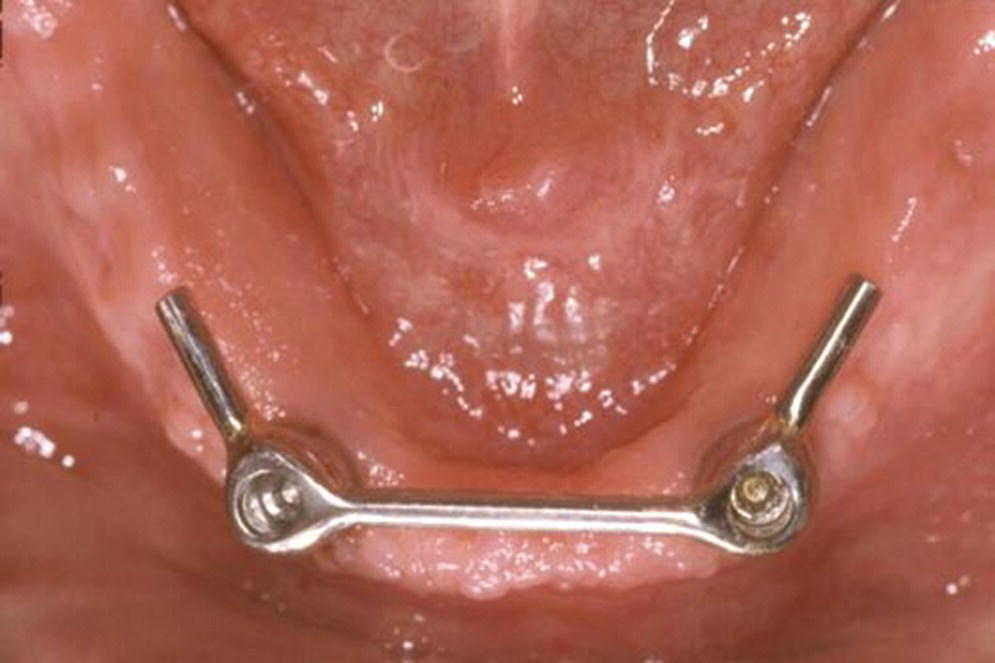
Figure 18.11 Two‐implant splinted bar design with distal cantilever extensions.
Maintenance
Ball attachments have been documented with less incidence of hyperplasia but more mechanical maintenance than bars, increasing ultimate patient costs for ball IRODs.65–68 On the other hand, when comparative maintenance outcomes were investigated with bars, telescopes, and Locator® attachments (Zest Anchors LLC), the latter performed superiorly over a 3‐year observation period.69 This coupled with the ease of changing the attachments and the low‐profile abutment/housing (3.2 mm) explains the popularity of the Locator® system, although in a cross‐over study, no patient preference was given to the Locator® attachment.70 The clinician can expect the two‐Locator® IROD over 3 years to require a reline in less than 20% of patients, and two sets of changes in the retentive attachments. There also has been a troubling finding of food impaction in the occlusal well of the abutment in 47% of patients after 7 years (Figure 18.12).71 A simple solution is to change the nylon attachments to the extended‐range set which has no internal doughnut (Figure 18.13). In a review of literature, there was a wide range of incidence of required relines from 8% to 40% for both IROD and ISOP designs.72,73 A functional wax refit technique74 using Adaptol wax sticks (Kaye Research Laboratories, Ashaway, RI) with 10 drops of vegetable oil, which can be heated up to 123 °F (50.5 °C) can facilitate an accurate pick‐up of attachments and the extension base tissue zone, which may reduce the frequency for this procedure (Figure 18.14a, b). This technique is also effective for other types of overdenture attachments (Figure 18.14c). A prospective maintenance evaluation of two‐, three‐, and four‐implant bar anchorage systems revealed 1.5 times more retention clip activation in the two‐implant (single round bar) design, as compared to the three‐implant (double round bar) or four‐implant (triple round bar) design.73 However, retention clip fracture occurred twice as much with three or four implants than with two implants. In response to the frequent maintenance issues seen in the four‐implant design, a rigid milled bar mesostructure intimately supporting a reinforced metal suprastructure retained with swivel latches75 (Figure 18.15) required three times less prosthodontic aftercare over 5 years when compared to resilient bar designs such as the Dolder or Hader bar systems (Figure 18.16).76,77 The reduction of micromotion in the rigid milled bar design compared to the resilient bar anchorage systems appears to be responsible for the reduced maintenance. When selecting a multiple‐implant design, although the rigid milled bar system with latches requires a higher initial investment, it is more cost effective than the resilient bar, while offering retention security.
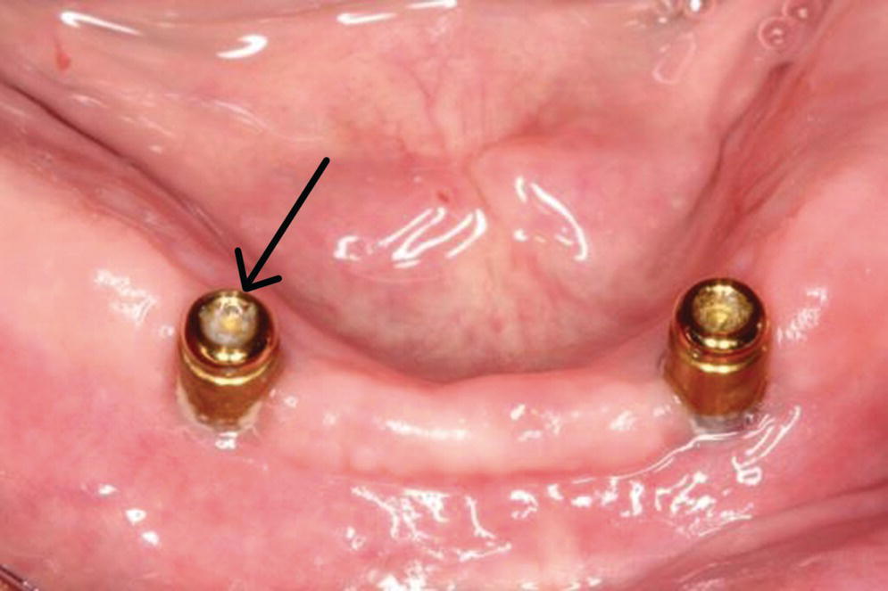
Figure 18.12 Food impaction disclosed in internal well of the Locator® abutment.
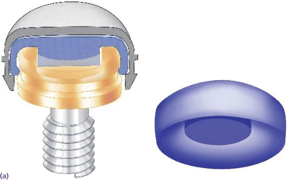
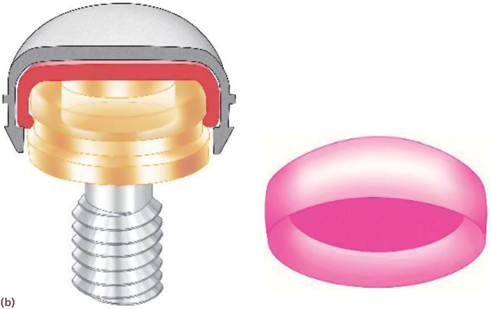
Figure 18.13 (a) Nylon attachment inside metal housing engaging the internal well of Locator® abutment. (b) Extended‐range nylon attachment inside metal housing not engaging the internal well of Locator® abutment.
Source: Courtesy of Jeff Miles.
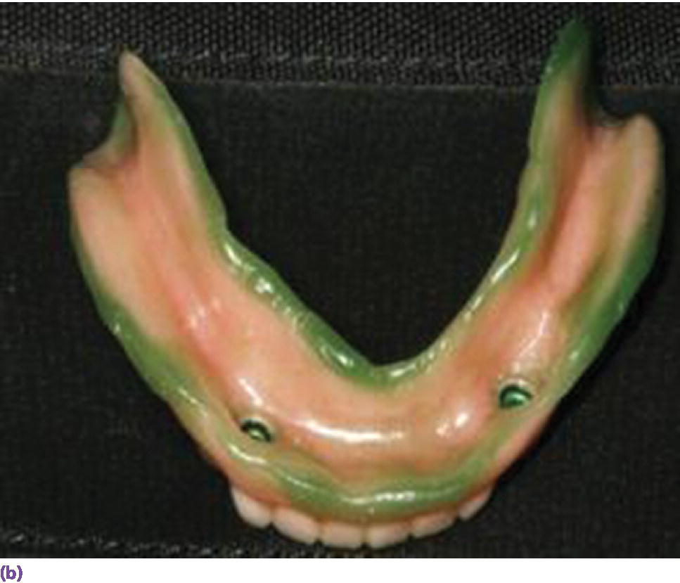
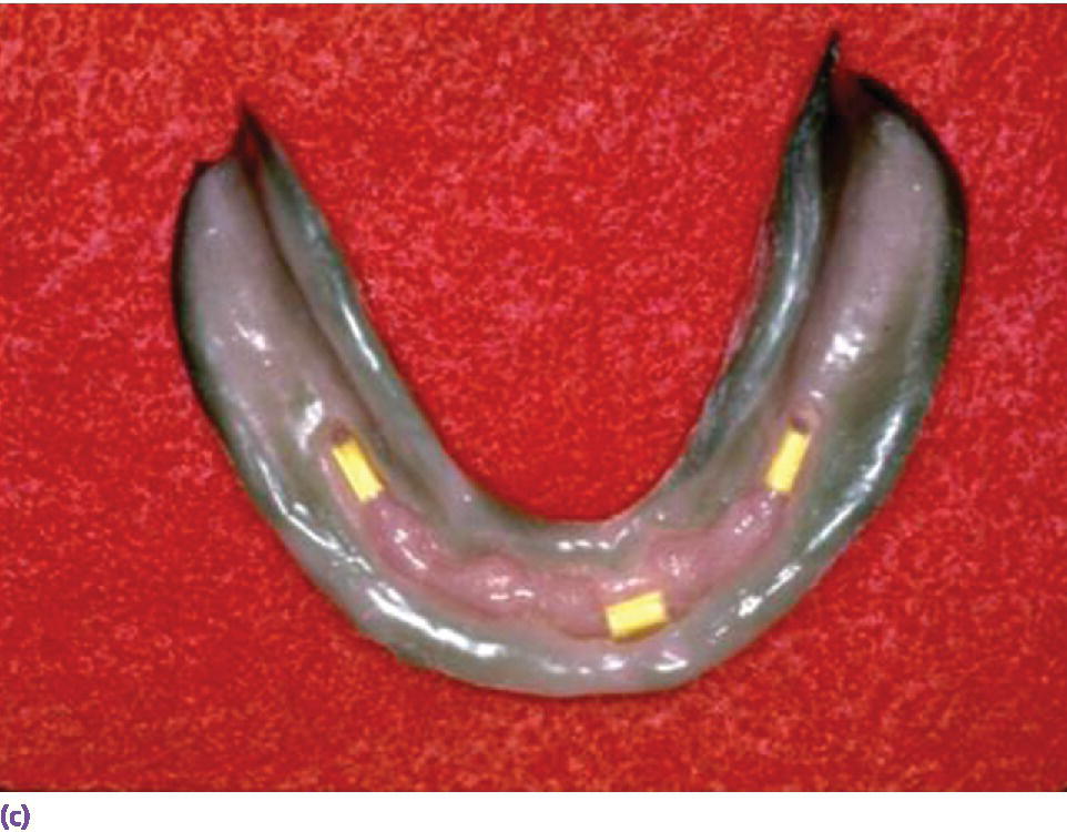
Figure 18.14 (a) Melted Adaptol® wax sticks (10 drops vegetable oil per stick) fusing at 123 °F (50.5 °C) in small pan. (b) Place heated wax in intaglio of implant overdenture with a #7 spatula, temper in 120 °F (48.8 °C) water bath, and place in mouth. Remove and add or subtract wax as needed to allow uniform seating on extension base and attachments. Have the patient reproduce functional movements and chew on a small cube of foam. Fins are evidence of underextensions. Show‐throughs in the flange area may be overextensions. Once the intaglio of the prosthesis is optimized, have the patient rinse with ice water, and remove and seal in a baggie of ice water for transport to lab for reline. (c) Functional wax technique for Hader bar overdenture design.
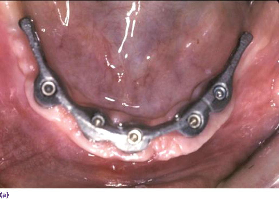
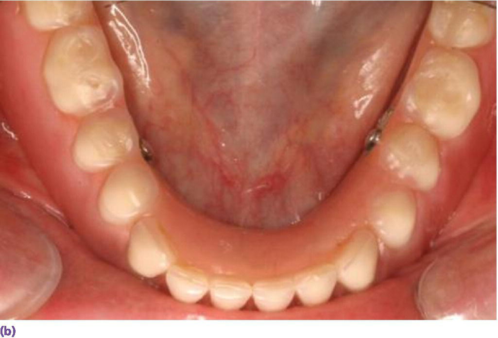
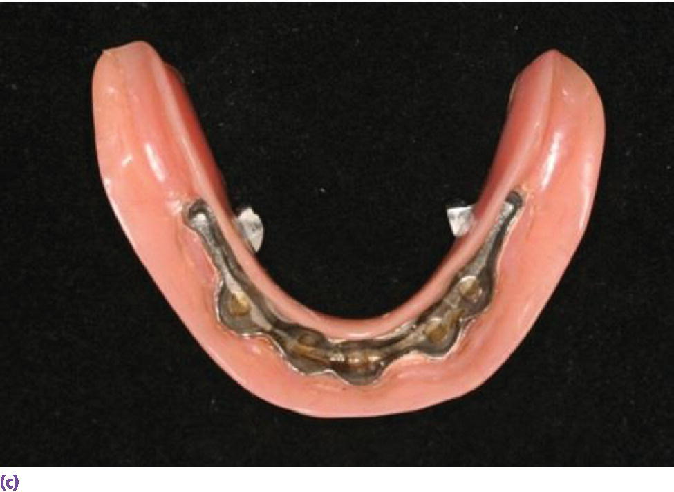
Figure 18.15 (a) Spark‐eroded milled bar anchorage system. (b) Milled bar overdenture suprastructure. (c) Intaglio of milled bar overdenture suprastructure revealing secondary bar and reinforcement.
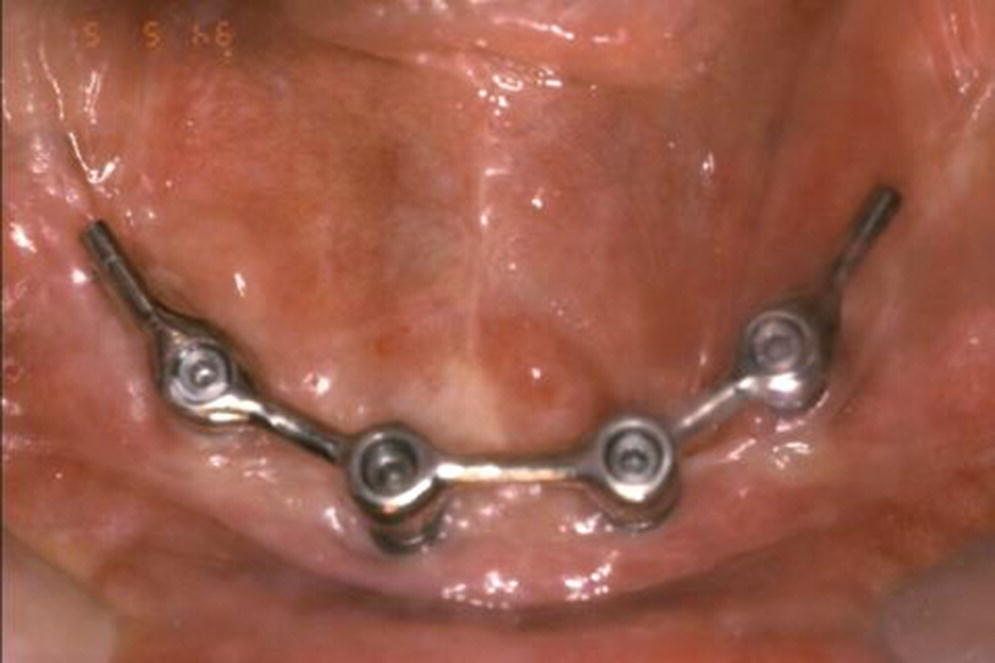
Figure 18.16 Resilient cantilevered Dolder bar anchorage system.
Immediate‐load protocols
Stay updated, free dental videos. Join our Telegram channel
VIDEdental - Online dental courses


