Class II Cast Metal Restorations
The cast metal restoration is versatile and is especially applicable to Class II onlay preparations. The process has many steps, involves numerous dental materials, and requires meticulous attention to detail. Typically, a dental laboratory is involved, and the dentist and the laboratory technician must be devoted to perfection. The high degree of satisfaction and service derived from a properly made cast metal restoration is a reward for the painstaking application required.1 The Class II inlay involves the occlusal surface and one or more proximal surfaces of a posterior tooth. When cusp tips are restored, the term onlay is used. The procedure requires two appointments: the first for preparing the tooth and making an impression, and the second for delivering the restoration to the patient. The fabrication process is referred to as an indirect procedure because the casting is made on a replica of the prepared tooth in a dental laboratory.
Material Qualities
The American Dental Association (ADA) Specification No. 5 for Dental Casting Gold Alloys requires a minimum total gold-plus-platinum-metals content of 75 weight percent (wt%). Such traditional high-gold alloys are unreactive in the oral environment and are some of the most biocompatible materials available to the restorative dentist.2 At present, four distinct groups of alloys are in use for cast restorations: (1) traditional high-gold alloys, (2) low-gold alloys, (3) palladium–silver alloys, and (4) base metal alloys. Each of the alternatives to high-gold alloys has required some modification of technique or acceptance of reduced performance, most commonly related to decreased tarnish resistance and decreased burnishability.3 Also, they have been associated with higher incidences of post-restorative allergy, most often exhibited by irritated soft tissue adjacent to the restoration.2
Initial Procedures
Occlusion
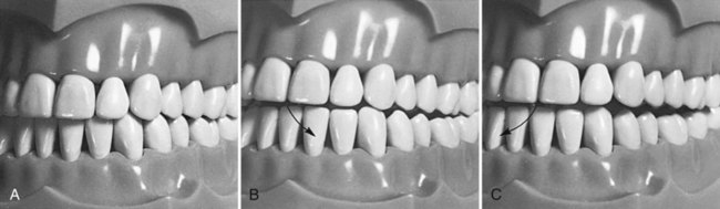
Before the anesthetic is administered and before preparation of any tooth, the occlusal contacts of teeth should be evaluated. As part of this evaluation, the dentist must decide if the existing occlusal relationships can be improved with the cast metal restoration. An evaluation should include (1) the occlusal contacts in maximum intercuspation where teeth are brought into full interdigitation and (2) the occlusal contacts that occur during mandibular movements (Fig. 17-1). The pattern of occlusal contacts influences the preparation design, selection of interocclusal records, and type of articulator or cast development needed.
Considerations for Temporary Restorations
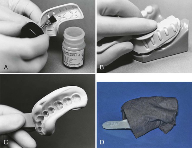
The technique involves making a preoperative impression with an elastic impression material. Alginate impression materials may be used and are relatively inexpensive. The preoperative impression may be made with a polyvinyl siloxane (PVS) impression material if additional accuracy, stability, and durability are required. If the tooth to be restored has any large defects such as a missing cusp, either of two methods may be used to reproduce the missing cusp in the temporary. First, an instrument can be used to remove the impression material in the area of the missing cusp or tooth structure, to simulate the desired form for the temporary restoration. Second, wax can be added to the tooth before the impression, as follows: The tooth is dried and large defects filled with utility wax. The wax is smoothed, and an impression is made by using a quadrant tray if no more than two teeth are to be prepared (Fig. 17-2, A). A full-arch tray may be used for greater stability. The tray filled with impression material is then seated (see Fig. 17-2, B). After the impression has set, the impression is removed and examined for completeness (see Fig. 17-2, C). Alginate impressions can distort quickly if they are allowed to gain or lose moisture, so the impression is wrapped in wet paper towels to serve as a humidor (see Fig. 17-2, D). Pre-operative polyvinyl impressions do not need to be wrapped. The preoperative impression is set aside for later use in forming the temporary restoration.
Tooth Preparations for Class II Cast Metal Restorations
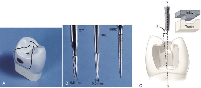
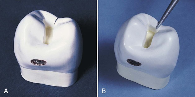
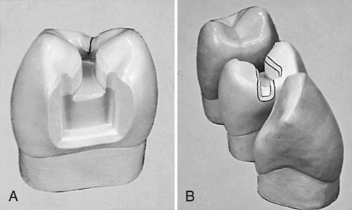
A small, distal, cavitated caries lesion in the maxillary right first premolar is used to illustrate the classic two-surface preparation for an inlay (Fig. 17-3, A). Treatment principles for other defects are presented later. As indicated previously, few small one-surface or two-surface inlays are done. Because the description of a small tooth preparation presents the basic concepts, it is used to illustrate the technique. More extensive tooth preparations are presented later.
Tooth Preparation for Class II Cast Metal Inlays
Initial Preparation
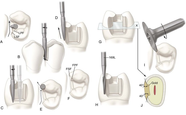
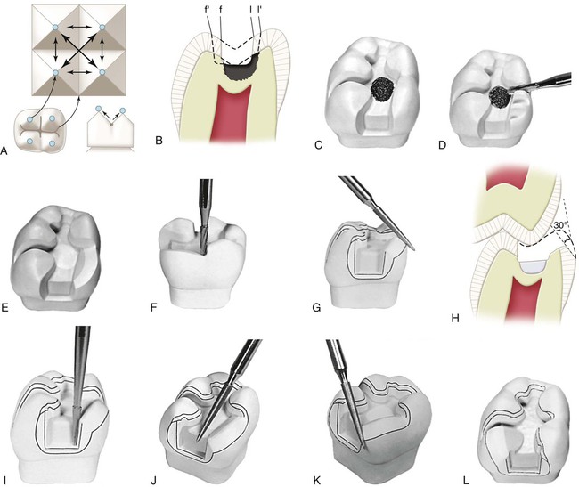
Carbide burs used to develop the vertical internal walls of the preparation for cast metal inlays and onlays are plane cut, tapered fissure burs. These burs are plane cut so that the vertical walls are smooth. The side and end surfaces of the bur should be straight to aid in the development of uniformly tapered walls and smooth pulpal and gingival walls. Recommended dimensions and configurations of the burs to be used are shown in Figure 17-3, B. Suggested burs are the No. 271 and the No. 169L burs (Brasseler USA, Inc., Savannah, GA). Before using unfamiliar burs, the operator is cautioned to verify measurements to judge the depth into the tooth during preparation. The sides and end surface of the No. 271 bur meet in a slightly rounded manner so that sharp, stress-inducing internal angles are not formed in the preparation.4 The marginal bevels are placed with a slender, fine-grit, flame-shaped diamond instrument such as the No. 8862 bur (Brasseler USA, Inc.).
Throughout the preparation for a cast inlay, the cutting instruments used to develop the vertical walls are oriented to a single “draw” path, usually the long axis of the tooth crown, so that the completed preparation has draft (no undercuts) (see Fig. 17-3, C). The gingival-to-occlusal divergence of these preparation walls may range from 2 to 5 degrees per wall from the line of draw. If the vertical walls are unusually short, a maximum of 2 degrees occlusal divergence is desirable to increase retention potential. As the occlusogingival height increases, the occlusal divergence should increase because lengthy preparations with minimal divergence (more parallel) may present difficulties during the seating and withdrawal of the restoration.
Occlusal Step
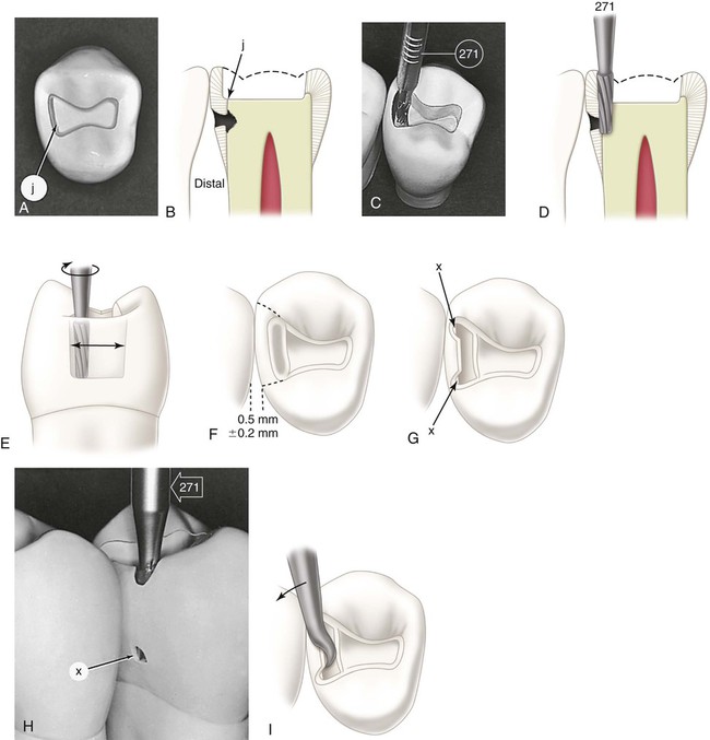
With the No. 271 carbide bur held parallel to the long axis of the tooth crown, the dentist enters the fossa or pit closest to the involved marginal ridge, using a punch cut to a depth of 1.5 mm to establish the depth of the pulpal wall (Fig. 17-4, A and B). In the initial preparation, this specified depth should not be exceeded, regardless of whether the bur end is in dentin, caries, old restorative material, or air. The bur should be rotating at high speed (with air-water spray) before application to the tooth and should not stop rotating until it is removed; this minimizes perceptible vibration and prevents breakage or chipping of the bur blades. A general rule is to maintain the long axis of the bur parallel to the long axis of the tooth crown at all times (see Fig. 17-4, B and C). For mandibular molars and second premolars whose crowns tilt slightly lingually, this rule dictates that the bur should also be tilted slightly (5–10 degrees) lingually to conserve the strength of the lingual cusps (see Fig. 17-4, D). When the operator is cutting at high speeds, a properly directed air-water spray is used to provide the necessary cooling and cleansing effects.5
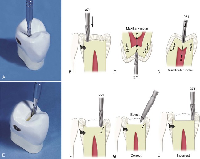
Maintaining the 1.5-mm initial depth and the same bur orientation, the dentist extends the preparation outline mesially along the central groove or fissure to include the mesial fossa or pit (see Fig. 17-4, E and F). Ideally, the faciolingual dimension of this cut should be minimal. The dentist takes care to keep the mesial marginal ridge strong by not removing the dentin support of the ridge (see Fig. 17-4, F and H). The use of light intermittent pressure minimizes heat production on the tooth surface and reduces the incidence of enamel crazing ahead of the bur. Occasionally, a fissure extends onto the mesial marginal ridge. This defect, if shallow, may be treated with enameloplasty, or it may be included in the outline form with the cavosurface bevel, which is applied in a later step in the tooth preparation (see Fig. 17-4, G).
Enameloplasty, as presented in earlier chapters, occasionally reduces extension along the fissures, conserving the tooth structure vital for pulp protection and the strength of the remaining tooth crown. The extent to which enameloplasty can be used usually cannot be determined until the operator is in the process of extending the preparation wall, when the depth of the fissure in the enamel wall can be observed (Fig. 17-5). When enameloplasty shows a fissure in a marginal ridge to be deeper than one third the thickness of enamel, the procedures described in the later section should be used.
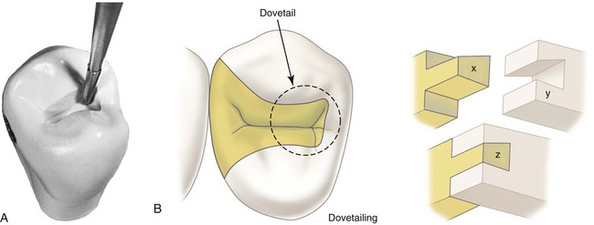
Extend to include faulty facial and lingual fissures radiating from the mesial pit. During this extension cutting, the operator is cautioned again not to remove the dentin support of the proximal marginal ridge. To conserve the tooth structure and the strength of the remaining tooth, the final extension up these fissures can be accomplished with the slender No. 169L carbide bur (Fig. 17-6, A). The tooth structure and strength can be conserved further by using (1) enameloplasty of the fissure ends, when possible, and (2) the marginal bevel of the final preparation to include (eliminate) the terminal ends of these fissures in the outline form. The facial and lingual extensions in the mesial pit region should provide the desired dovetail retention form, which resists distal displacement of the inlay (see Fig. 17-6, B). When these facial and lingual grooves are not faulty, sufficient facial extension in the mesial pit region should be made to provide this dovetail retention form against distal displacement. Minor extension in the transverse ridge area to include any remaining facial or lingual caries may necessitate additional facial or lingual extension in the mesial pit to provide this dovetail feature. (During such facial or lingual extensions to sound tooth structure, the bur depth is maintained at 1.5 mm.) If major facial or lingual extension is required to remove undermined occlusal enamel, capping the weak remaining cuspal structure and additional features in the preparation to provide adequate retention and resistance forms may be indicated. These considerations are discussed in subsequent sections.
Continuing at the initial depth, the occlusal step is extended distally into the distal marginal ridge sufficiently to expose the junction of the proximal enamel and dentin (Fig. 17-7, A and B). While extending distally, the dentist progressively widens the preparation to the desired faciolingual width in anticipation of the proximal box preparation. The increased faciolingual width enables the facial and lingual walls of the box to project (visually) perpendicularly to the proximal surface at positions that clear the adjacent tooth by 0.2 to 0.5 mm (see Fig. 17-7, F). The facial and lingual walls of the occlusal step should go around the cusps in graceful curves, and the prepared isthmus in the transverse ridge ideally should be only slightly wider than the bur, thus conserving the dentinal protection for the pulp and maintaining the strength of the cusps. If the occlusal step has been prepared correctly, any caries on the pulpal floor should be uncovered by facial and lingual extensions to sound enamel (supported by dentin).
Proximal Box
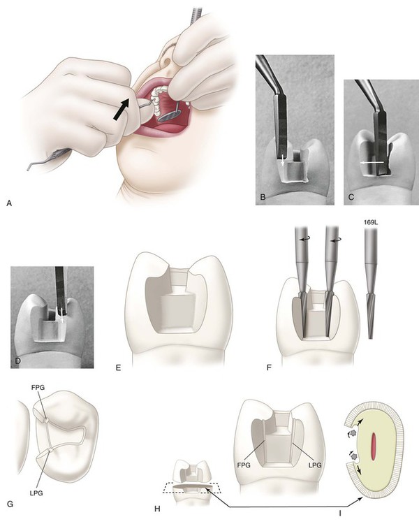
Continuing with the No. 271 carbide bur, the distal enamel is isolated by cutting a proximal ditch (see Fig. 17-7, C through F). The harder enamel should guide the bur. Slight pressure toward enamel is necessary to prevent the bur from cutting only dentin. If the bur is allowed to cut only dentin, the resulting axial wall would be too deep. The mesiodistal width of the ditch should be 0.8 mm (the tip diameter of the bur) and prepared approximately two thirds (0.5 mm) at the expense of dentin and one third (0.3 mm) at the expense of enamel. The gingival extension of this cut may be checked with the length of the bur by first measuring the depth from the height of the marginal ridge and then removing the bur and holding it beside the tooth. A periodontal probe also may be used for this measurement. While penetrating gingivally, the dentist extends the proximal ditch facially and lingually beyond the caries to the desired position of the facioaxial and linguoaxial line angles. If the caries lesion is minimal, the ideal extension facially and lingually is performed as previously described (see Fig. 17-7, F). Ideal gingival extension of a minimal, cavitated lesion eliminates caries on the gingival floor and provides a 0.5-mm clearance of the unbeveled gingival margin with the adjacent tooth. Moderate to extensive caries on the proximal surface dictates continued extension of the proximal ditch to the extent of the caries at the dentinoenamel junction (DEJ), but not pulpally (see Fig. 17-11, D). When preparing the proximal portion of the preparation, the dentist maintains the side of the bur at the specified axial wall depth regardless of whether it is in dentin, caries, old restorative material, or air. The operator should guard against overcutting the facial, lingual, and gingival walls, which would not conserve the tooth structure and could result in (1) overextension of the margins in the completed preparation, (2) a weakened tooth, and (3) possible injury of soft tissue. Because the proximal enamel diminishes in thickness from the occlusal to gingival level, the end of the bur is closer to the external tooth surface as the cutting progresses gingivally. The axial wall should follow the contour of the tooth faciolingually. Any carious dentin on the axial wall should not be removed at this stage of the preparation.
With the No. 271 carbide bur, the dentist makes two cuts, one at the facial limit of the proximal ditch and the other at the lingual limit, extending from the ditch perpendicularly toward the enamel surface (in the direction of the enamel rods) (see Fig. 17-7, G). These cuts are extended until the bur is nearly through the marginal ridge enamel (the side of the bur may emerge slightly through the surface at the level of the gingival floor) as shown in Figure 17-7, H. This weakens the enamel by which the remaining isolated portion is held. Also, the level of the gingival floor is verified by observing where the end of the bur emerged through the proximal surface. If indicated, additional gingival extension can be accomplished while the remaining enamel still serves to guide the bur and to prevent it from marring the proximal surface of the adjacent tooth. At this time, however, the remaining wall of enamel often breaks away during cutting, especially when high speeds are employed. If the isolated wall of enamel is still present, it can be fractured out with a spoon excavator (see Fig. 17-7, I). At this stage, the ragged enamel edges left from breaking away the proximal surface may be touching the adjacent tooth.
Planing the distofacial, distolingual, and gingival walls by hand instruments to remove all undermined enamel may be indicated if minimal extension is needed to fulfill an esthetic objective. Depending on access, the operator can use a No. 15 (width) straight chisel, bin-angle chisel (Fig. 17-8), or enamel hatchet. For a right-handed operator, the distal beveled bin-angle chisel is used on the distofacial wall of a disto-occlusal preparation for the maxillary right premolar. The dentist planes the wall by holding the instrument in the modified palm-and-thumb grasp and uses a chisel-like motion in an occlusal-to-gingival direction (see Fig. 17-8, A and B). The dentist planes the gingival wall by using the same instrument as a hoe, scraping in a lingual-to-facial direction (see Fig. 17-8, C). In this latter action, the axial wall may be planed with the side edge (secondary edge) of the blade. The distolingual wall is planed smooth by using the bin-angle chisel with the mesial bevel (see Fig. 17-8, D). When proximal caries is minimal, ideal facial and lingual extensions at this step in the preparation result in margins that clear the adjacent tooth by 0.2 to 0.5 mm.
The experienced operator usually does not use chisel hand instruments during the preparation for inlays, considering that the narrow, flame-shaped, fine-grit diamond instrument, when artfully used, removes ragged, weak enamel during application of the cavosurface bevel and flares and causes the patient to be less apprehensive (see Figs. 17-12 and 17-13). If the diamond instrument is to be used exclusively in finishing the enamel walls and margins, this procedure is postponed until after the removal of any remaining infected dentin, old restorative material, or both and the application of any necessary base. Waiting prevents any hemorrhage (which occasionally follows the beveling of the gingival margin) from hindering (1) the suitable removal of remaining infected dentin and old restorative material and (2) the proper application of a necessary base. Hand instruments are more useful on the mesiofacial surfaces of maxillary premolars and first molars, where minimal extension is desired to prevent an unsightly display of metal.
Shallow (0.3-mm deep) retention grooves may be cut in the facioaxial and linguoaxial line angles with the No. 169L carbide bur (see Fig. 17-8, E through I). These grooves are indicated especially when the prepared tooth is short. When properly positioned, the grooves are in sound dentin, close to but not contacting, the DEJ. The long axis of the bur must be held parallel to the line of draw. Preparing these grooves may be postponed until after any required bases are applied during the final preparation.
Final Preparation
Removal of Infected Carious Dentin and Pulp Protection
After the initial preparation has been completed, the dentist evaluates the internal walls of the preparation visually and tactilely (with an explorer) for indications of any remaining carious dentin. If carious dentin remains, and if it is judged to be infected, but shallow or moderate (≥1 mm of remaining dentin between the caries and the pulp), satisfactory isolation for the removal of such caries and the application of any necessary base may be attained by reducing salivation through anesthesia and the use of cotton rolls, a saliva ejector, and gingival retraction cord. The retraction cord also serves to widen the gingival sulcus and slightly retract the gingiva in preparation for beveling and flaring the proximal margins (Fig. 17-9; see also Fig. 17-12, A and B). For insertion of the cord, see the sections on preparation of bevels and flares and tissue retraction. The removal of the remaining caries and placement of a necessary base can be accomplished during the time required for the full effect of the inserted cord. A slowly revolving round bur (No. 2 or No. 4) or spoon excavator is used to remove carious infected dentin (see Fig. 17-9, F and G). If a bur is used, visibility can be improved by using air alone. This excavation is done just above stall-out speed with light, intermittent cutting. The operator should avoid unnecessarily desiccating the exposed dentin during this procedure.
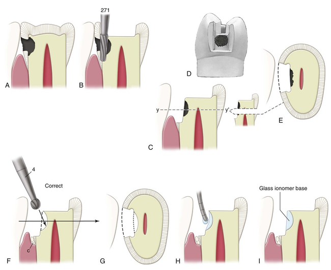
Light-cured glass ionomer cement may be mixed and applied with a suitable applicator to these shallow (or moderately deep) excavated regions to the depth and form of the ideally prepared surface. Placing a base takes little time and should be considered because it results in working dies (subsequently in the laboratory phase) that have preparation walls with no undercuts and “ideal” position and contour. Also, applying a base at this time minimizes additional irritation of the pulp during subsequent procedures necessary for the completion of the restoration. The light-cured glass ionomer adheres to the tooth structure and does not require retentive undercuts when the base is small to moderate. The material is applied by conveying small portions on the end of a periodontal probe and is light-cured when the correct form has been achieved (see Fig. 17-9, H and I). Any excess cement can be trimmed back to the ideal form with the No. 271 carbide bur after the cement has hardened.
 The exposure is small (<0.5 mm in diameter).
 The tooth has been asymptomatic, showing no signs of pulpitis.
 Any hemorrhage from the exposure site is easily controlled.

 A clean, uncontaminated operating field is maintained (i.e., by using a rubber dam).
If the excavation closely approaches the pulp or if a direct pulp cap is indicated, the dentist should first apply a lining of calcium hydroxide using a flow technique (without pressure). This calcium hydroxide liner should cover and protect any possible near or actual exposure and extend over a major portion of the excavated dentinal surface (Fig. 17-10, A). Although undetected, an exposed recessional tract of a pulp horn may exist in any deep excavation. Calcium hydroxide treatment of an exposed, healthy pulp promotes the formation of a dentin bridge, which would close the exposure.3 The peripheral 0.5 to 1 mm of the dentin excavation should be left available for bonding the subsequently applied light-cured glass ionomer cement base.
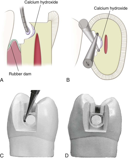
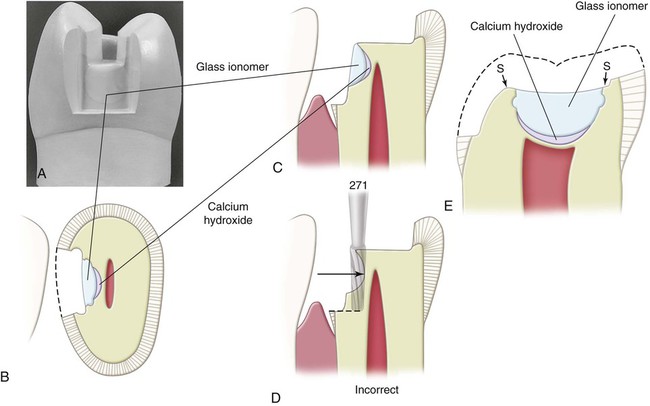
Although the light-cured glass ionomer cement is adhesive to dentin, large cement bases can be subjected to considerable stresses during fabrication of the temporary and try-in and cementation of the cast metal restoration. Also, if a calcium hydroxide liner has been applied, less dentin is available for adhesive bonding. In these circumstances, small mechanical undercuts can increase the retention of the glass ionomer base. If suitable undercuts are not present after the removal of infected dentin, retention coves are placed with the No.  carbide bur (see Fig. 17-10, B through D). These coves are placed in the peripheral dentin of the excavation and are as remote from the pulp as possible. Light-cured glass ionomer cement should be applied without pressure. It should completely cover the calcium hydroxide lining and some peripheral dentin for good adhesion (Fig. 17-11). The cement base should be sufficiently thick in dimension to protect the thin underlying dentin and the calcium hydroxide liner from subsequent stresses. Usually, good resistance form dictates that the pulpal wall should not be formed entirely by a cement base; rather, in at least two regions, one diametrically across the excavation from the other, the pulpal wall should be in normal position, flat, and formed by sound dentin (see region S in Fig. 17-11, E, which depicts basing in a mandibular molar). The dentist should consider the addition of other retention features such as proximal grooves if a major portion of a proximal axial wall is composed mostly of cement base because this base should not be relied on for contributing to retention of the cast restoration (see Fig. 17-8, F).
Preparation of Bevels and Flares
After the cement base (where indicated) is completed, the slender, flame-shaped, fine-grit diamond instrument is used to bevel the occlusal and gingival margins and to apply the secondary flare on the distolingual and distofacial walls. This should result in 30- to 40-degree marginal metal on the inlay (see Figs. 17-12, H, 17-13, J, and 17-14, B). This cavosurface design helps seal and protect the margins and results in a strong enamel margin with an angle of 140 to 150 degrees. A cavosurface enamel angle of more than 150 degrees is incorrect because it results in a less defined enamel margin (finish line), and the marginal cast metal alloy is too thin and weak if its angle is less than 30 degrees. Conversely, if the enamel margin is 140 degrees or less, the metal is too bulky and difficult to burnish when its angle is greater than 40 degrees (see Fig. 17-14, F).
Usually, it is helpful to insert a gingival retraction cord of suitable diameter into the gingival sulcus adjacent to the gingival margin and leave it in place for several minutes just before the use of the flame-shaped diamond instrument on the proximal margins (Fig. 17-12, A through C). The cord should be small enough in diameter to permit relatively easy insertion and to preclude excessive pressure against the gingival tissue, and yet it should be large enough to widen the sulcus to about 0.5 mm. Immediately before the flame-shaped diamond instrument is used, the cord may be removed to create an open sulcus that improves visibility for beveling the gingival margin and helps prevent injury and subsequent hemorrhage of gingival tissue. Some operators prefer to leave the cord in the sulcus while placing the gingival bevel.
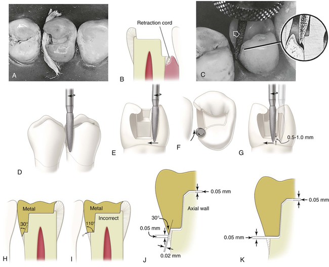
Using the flame-shaped diamond instrument that is rotating at high speed, the dentist prepares the lingual secondary flare (see Fig. 17-12, D through F; Fig. 17-13, A). The dentist approaches from the lingual embrasure (see Fig. 17-12, F), moving the instrument mesiofacially. The direction of the distolingual wall and the position of the distolingual margin are compared before and after this extension (see Figs. 17-8, G, and 17-13, A). The distolingual wall extends from the linguoaxial line angle into the lingual embrasure in two planes (see Fig. 17-13, A). The first is termed lingual primary flare; the second is termed lingual secondary flare. During this (secondary) flaring operation, the long axis of the instrument is held nearly parallel to the line of draw, with only a slight tilting mesially and lingually for assurance of draft (see Fig. 17-12, D and E), and the direction of translation of the instrument is that which results in a marginal metal angle of 40 degrees (see Figs. 17-12, F, and 17-13, J).
The dentist bevels the gingival margin by moving the instrument facially along the gingival margin (see Figs. 17-12, G, and 17-13, A). While cutting the gingival bevel, the rotational speed should be reduced to increase the sense of touch; otherwise, over-beveling may result. The instrument should be tilted slightly mesially to produce a gingival bevel with the correct steepness to result in 30-degree marginal metal (see Fig. 17-12, C, H, and J). If the instrument is not tilted in this manner, the bevel is too steep, resulting in gingival bevel metal that is too thin (<30-degree metal) and too weak. Although the instrument is tilted mesially, its long axis must not tilt facially or lingually (see Fig. 17-12, G). The gingival bevel should be 0.5 to 1 mm wide and should blend with the lingual secondary flare.
The operator completes the gingival bevel and prepares the facial secondary flare (see Fig. 17-13, A through F). The long axis of the instrument during this secondary flare is again returned nearly to the line of draw, with only a small tilting mesially and facially, and the direction of translation of the instrument is that which results in 40-degree marginal metal (see Fig. 17-13, E and J). When the adjacent proximal surface (mesial of the second premolar) is not being prepared, care must be exercised to avoid abrading the adjacent tooth and overextending the distofacial margin. To prevent such abrasion or overextension, the instrument may be raised occlusally (using the narrower portion at its tip end) to complete the most facial portion of the wall and margin (see Fig. 17-13, D). Also, the more slender No. 169L carbide bur may be used, rather than the flame-shaped diamond instrument (see Fig. 17-13, H). The No. 169L bur produces an extremely smooth surface to the secondary flare and a smooth, straight distofacial margin. When access permits, a fine-grit sandpaper disk may be used on the facial and lingual walls and on the margins of the proximal preparation, especially when minimal extension of the facial margin is desired (see Fig. 17-13, I). This produces smooth walls and helps create respective margins that are straight (not ragged) and sound.
The gingival bevel serves the following purposes:
 Weak enamel is removed. If the gingival margin is in the enamel, it would be weak if not beveled because of the gingival declination of the enamel rods (see Fig. 17-12, I).
 The bevel results in 30-degree metal that is burnishable (on the die) because of its angular design (see Fig. 17-12, H). Bulky 110-degree metal along an unbeveled margin is not burnishable (see Fig. 17-12, I).
 A lap, sliding fit is produced at the gingival margin (see Fig. 17-12, J). This helps improve the fit of the casting in this region. With the prescribed gingival bevel, if the inlay fails to seat by 50 µm, the void between the bevel metal and the gingival bevel on the tooth may be 20 µm; however, failure to apply such a bevel would result in a void (and a cement line) as great as in the failure to seat (see Fig. 17-12, K).
The secondary flare is necessary for several reasons: (1) The secondary flaring of the proximal walls extends the margins into the embrasures, making these margins more self-cleaning and more accessible to finishing procedures during the inlay insertion appointment, and does so with conservation of dentin. (2) The direction of the flare results in 40-degree marginal metal (see Fig. 17-13, J). Metal with this angular design is burnishable; however, metal shaped at a larger angle is unsatisfactory for burnishing; metal with an angle less than 30 degrees is too thin and weak, with a corresponding enamel margin that is too indefinite and ragged. (3) A more blunted and stronger enamel margin is produced because of the secondary flare.
The flame-shaped, fine-grit diamond instrument also is used for occlusal bevels. The width of the cavosurface bevel on the occlusal margin should be approximately one-fourth the depth of the respective wall (Fig. 17-14, A and B). The exception to the rule is when a wider bevel is desired to include an enamel defect (see Fig. 17-14, G and H). The resulting occlusal marginal metal of the inlay should be 40-degree metal; the occlusal marginal enamel is 140-degree enamel (see Fig. 17-14, B and E). Beveling the occlusal margins in this manner increases the strength of the marginal enamel and helps seal and protect the margins. While beveling the occlusal margins, a guide to diamond positioning is to maintain an approximate 40-degree angle between the side of the instrument and the external enamel surface; this also indicates when an occlusal bevel is necessary (see Fig. 17-14, A). If the cusp inclines are so steep that the diamond instrument, when positioned at a 40-degree angle to the external enamel surface, is parallel with the enamel preparation wall, no bevel is indicated (see Fig. 17-14, C). By using this technique, it can be seen that margins on the proximal marginal ridges always require a cavosurface bevel (see Fig. 17-14, D and I). Failure to apply a bevel in these regions leaves the enamel margin weak and subject to injury by fracture before the inlay insertion appointment and during the try-in of the inlay when burnishing the marginal metal. Also, failure to bevel the margins on the marginal ridges results in metal alloy that is difficult to burnish because it is too bulky (see Fig. 17-14, F). Similarly, the importance of extending the occlusal bevel to include the portions of the occlusal margin that cross over the marginal ridge cannot be overemphasized (see Fig. 17-14, H and I). These margins are beveled to result in 40-degree marginal metal. Otherwise, fracture of the enamel margin in such stress-vulnerable regions may occur in the interim between the preparation and the cementation appointment.
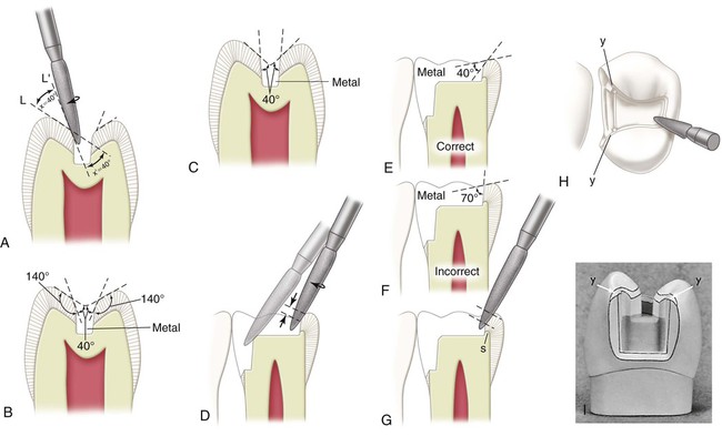
The diamond instrument also is used to bevel the axiopulpal line angle lightly (see Fig. 17-14, D). Such a bevel provides a thicker and stronger wax pattern at this critical region. The desirable metal angle at the margins of inlays is 40 degrees except at the gingival margins, where the metal angle should be 30 degrees. The completed preparation is illustrated in Figure 17-15, A.
Modifications in Inlay Tooth Preparations
Mesio-occluso-distal Preparation
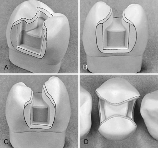
If a marginal ridge is severely weakened because of excessive extension, the preparation outline often should be altered to include the proximal surface. The disto-occlusal preparation illustrated in the previous section would be extended to a mesio-occluso-distal preparation (Fig. 17-16, A through C; see also Fig. 17-15, B through D). The decision to extend the preparation in this manner calls for clinical judgment as to whether the remaining marginal ridge would withstand occlusal forces without fracture. A fortunate factor in favor of not extending the preparation is that such ridge enamel usually is composed of gnarled enamel and is stronger than it appears. Caries present on both proximal surfaces would result in a mesio-occluso-distal preparation and restoration. The only difference in technique as described previously is the inclusion of the other proximal surface.
Modifications of Class II Preparation for Esthetics
For esthetic reasons, minimal flare is desired for the mesiofacial proximal wall in maxillary premolars and first molars in Class II cast metal preparations (see Fig. 17-15, D). The mesiofacial margin is minimally extended facially of the contact to such a position that the margin is barely visible from a facial viewing position. To accomplish this, the secondary flare is omitted, and the wall and margin are developed with (1) a chisel or enamel hatchet and final smoothing with a fine-grit paper disk or (2) a narrow diamond or bur when access permits.
Facial or Lingual Surface Groove Extension
Sometimes, a faulty facial groove (fissure) on the occlusal surface is continuous with a faulty facial surface groove (mandibular molars), or a faulty distal oblique groove on the occlusal surface is continuous with a faulty lingual surface groove (maxillary molar). This situation requires extension of the preparation outline to include the fissure to its termination (Fig. 17-17; see also Fig. 17-19, C). Occasionally, the operator may extend further gingivally than the fissure length to improve retention form. Such groove extensions, when sufficiently long, are effective for increasing retention. Likewise, this extension may be indicated to provide sufficient retention form even though the facial or lingual surface grooves are not fissured.
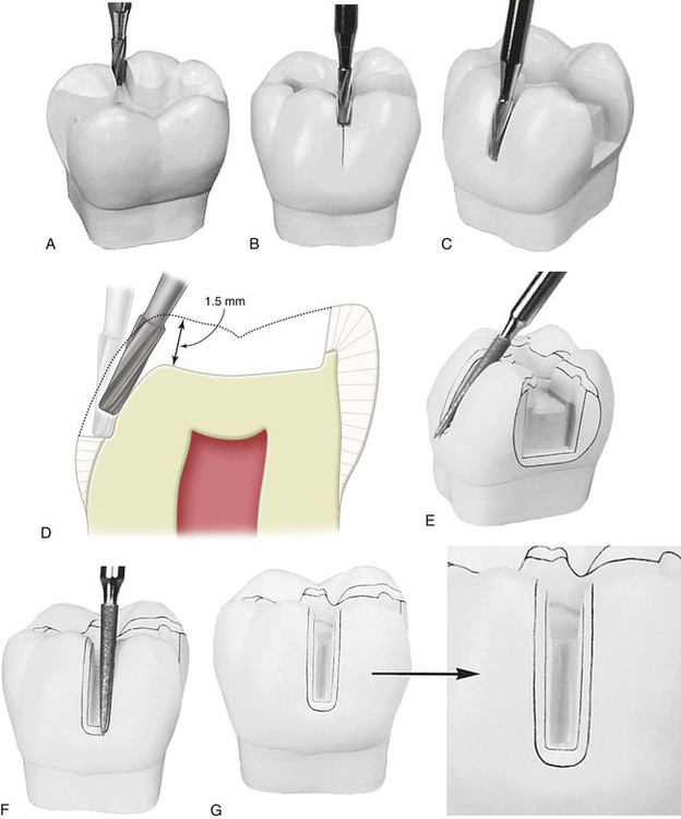
For extension onto the facial surface, the dentist uses the No. 271 carbide bur held parallel to the line of draw and extends through the facial ridge (see Fig. 17-17, A and B). The depth of the cut should be 1.5 mm. The floor (pulpal wall) should be continuous with the pulpal wall of the occlusal portion of the preparation (see Fig. 17-17, D).
With the bur still aligned with the path of draw, the dentist uses the side of the bur to cut the facial surface portion of this extension (see Fig. 17-17, C). The diameter of the bur serves as a depth gauge for the axial wall, which is in dentin. The blade portion of the No. 271 bur is 0.8 mm in diameter at its tip end and 1 mm at the neck; the axial wall depth should approximate 1 mm or slightly more. The bur should be tilted lingually as it is drawn occlusally, to develop the uniform depth of the axial wall (see Fig. 17-17, D). The same principles apply for the extension of a lingual surface groove.
When a facial or lingual groove is included, it also must be beveled. With the flame-shaped, fine-grit diamond instrument, the operator bevels the gingival margin (using no more than one third the depth of the gingival floor) to provide for 30-degree marginal metal (see Fig. 17-17, E). The operator applies a light bevel on the mesial and distal margins that is continuous with the occlusal and gingival bevels and results in 40-degree metal at these margins (see Fig. 17-17, F and G). The bevel width around the extended groove is approximately 0.5 mm.
Class II Preparation for Abutment Teeth and Extension Gingivally to Include Root-Surface Lesions
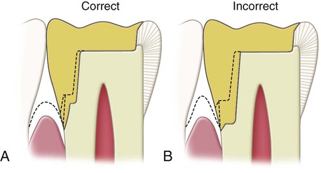
The following modified preparation is recommended when further gingival extension is indicated to include a root lesion on the proximal surface. The gingival extension should be accomplished primarily by lengthening the gingival bevel, especially when preparing a tooth that has a longer clinical crown than normal as a result of gingival recession. It is necessary to extend (gingivally) the gingival floor only slightly, and although the axial wall consequently must be moved pulpally, this should be minimal. If additional extension of the gingival floor is necessary, it should not be as wide pulpally as when the floor level is at a normal position (Fig. 17-18, A). These considerations are necessary because of the draft requirement and because the tooth is smaller apically. Extending the preparation gingivally without these modifications would result in a dangerous encroachment of the axial wall on the pulp (see Fig. 17-18, B).
Maxillary First Molar with Unaffected, Strong Oblique Ridge
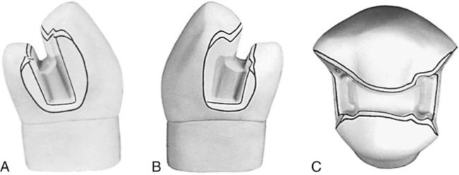
When a maxillary first molar is to be restored, consideration should be given to preserving the oblique ridge if it is strong and unaffected, especially if only one proximal surface is carious. A mesio-occlusal preparation for an inlay is illustrated in Figure 17-19, A and B. If a distal surface lesion appears subsequent to the insertion of a mesio-occlusal restoration, the tooth may be prepared for a disto-occluso-lingual inlay (see Fig. 17-19, H and I). The disto-occluso-lingual restoration that caps the distolingual cusp is preferable to the disto-occlusal restoration because it protects the miniature distolingual cusp from subsequent fracture. The disto-occluso-lingual preparation requires diligent application to develop satisfactory retention and resistance forms. Retention form is attained by (1) creating a maximum of 2-degree occlusal divergence of the vertical walls, (2) accentuating some line angles, and (3) extending the lingual surface groove to create an axial wall height in this extension of at least 2.5 mm occlusogingivally. The proper resistance form dictates (1) routine capping of the distolingual cusp and (2) maintaining sound tooth structure between the lingual surface groove extension and the distolingual wall of the proximal boxing.
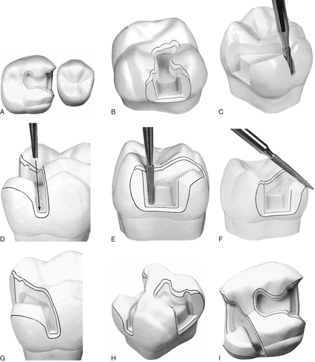
To prepare the disto-occluso-lingual preparation, the operator first reduces the distolingual cusp with the side of the No. 271 carbide bur. The cusp should be reduced a uniform 1.5 mm. Next, the operator completes the remaining occlusal step of the preparation with the No. 271 carbide bur. The operator prepares the proximal box portion of the preparation. The lingual groove extension is prepared only after the position of the distolingual wall of the proximal boxing is established. This permits the operator to judge the best position of the lingual surface groove extension to maintain a minimum of 3 mm of sound tooth structure between this extension and the distolingual wall; if this is not possible because of extensive caries, a more extensive type of preparation may be indicated (one that crosses the oblique ridge). One can use the side of the No. 271 carbide bur to produce the lingual surface groove extension (see Fig. 17-19, C). The diameter of the bur is the gauge for the depth (pulpally) of the axial wall in this extension, and the occlusogingival dimension of this axial wall is a minimum of 2.5 mm. With the end of this bur, the operator also establishes a 2-mm depth to the portion of the pulpal floor that connects the proximal boxing to the lingual surface groove extension. This additional depth to the pulpal floor helps strengthen the wax pattern and casting in later steps of fabrication. This should create a definite 0.5-mm step from the reduced distolingual cusp to the pulpal floor. Using the No. 169L carbide bur, the operator increases retention form in the disto-occluso-lingual preparation by (1) creating mesioaxial and distoaxial grooves in the lingual surface groove extension (see Fig. 17-19, D) and (2) preparing facial and lingual retention grooves in the distal boxing (see Fig. 17-19, E).
The dentist uses the flame-shaped, fine-grit diamond instrument to bevel the proximal gingival margin and to prepare the secondary flares on the proximal enamel walls and to bevel the lingual margins. A lingual counterbevel is prepared on the distolingual cusp that is generous in width and results in 30-degree metal at the margin (see Fig. 17-19, F). Occlusion should be checked at this point because the counterbevel should be sufficiently wide to extend beyond any occlusal contacts, either in maximum intercuspation or during mandibular movements. The bevel on the gingival margin of the lingual extension should be 0.5 mm wide and should provide for a 30-degree metal angle. The bevels on the mesial and distal margins of the lingual extension also are approximately 0.5 mm wide and result in 40-degree marginal metal.
Fissures in the Facial and Lingual Cusp Ridges or Marginal Ridges
In the preparation of Class II preparations for inlays, facial and lingual occlusal fissures may extend nearly to, or through, the respective facial and lingual cusp ridges, but not onto the facial or lingual surface. The proper outline form dictates that the preparation margin should not cross such fissures but should be extended to include them. For the occlusal step portion of the preparation, the dentist initially extends along the lingual fissure with the No. 271 carbide bur until only 2 mm of tooth structure remains between the bur and the lingual surface of the tooth. Additional lingual extension at this time is incorrect because it may remove the supporting dentin unnecessarily (Fig. 17-20, A and B). If this extension almost includes the length of the fissure, additional extension is achieved later by using the occlusal bevel; this bevel may be wider than conventional if the remaining fissure can be eliminated by such a wider bevel (see Fig. 17-20, C). Enameloplasty sometimes may eliminate the end portion of the fissure and provide a smooth enamel surface where previously a fault was present, thus reducing the extent of the required extension (see Fig. 17-20, D). If possible, the fissure should be included in the preparation outline without extending the margin to the height of the ridge. If the occlusal bevel places the margin on the height of the ridge, however, the marginal enamel likely is weak because of its sharpness and because of the inclination of the enamel rods in this region. The preparation outline should be extended just onto the facial or lingual surface (see Fig. 17-20, I and J). Such extension onto the facial or lingual surface also would be indicated if the fissure still remains through the ridge after enameloplasty (see Fig. 17-20, E).
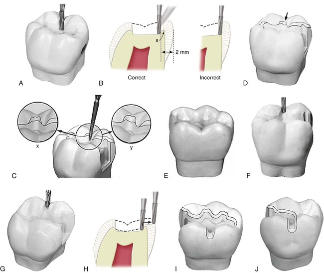
When necessary, extension through a cusp ridge is accomplished by cutting through the ridge at a depth of 1 mm with the No. 271 carbide bur (see Fig. 17-20, F and G). The dentist bevels the margins of the extension with the flame-shaped, fine-grit diamond instrument to provide for the desired 40-degree marginal metal on the occlusal, mesial, and distal margins and for 30-degree marginal metal on the gingival margin (see Fig. 17-20, C, D, I, and J). In the same manner, the operator should manage the fissures that may extend into or through a proximal marginal ridge, assuming that the proximal surface otherwise was not to be included in the outline form and that such fissure management does not extend the preparation outline near the adjacent tooth contact. This treatment particularly applies to a mesial fissure of the maxillary first premolar (Fig. 17-21). If this procedure extends the margin near or into the contact, the outline form on the affected proximal surface must be extended to include the contact, as for a conventional proximal surface preparation.
Cusp-Capping Partial Onlay
The term partial onlay is used when a cast metal restoration covers and restores at least one but not all of the cusp tips of a posterior tooth. The facial and lingual margins on the occlusal surface frequently must be extended toward the cusp tips to the extent of the existing restorative materials and to uncover caries (Fig. 17-22, B and C). Undermined occlusal enamel should be removed because it is weak; removing such enamel provides access for the proper excavation of caries. When the occlusal outline is extended up the cusp slopes more than half the distance from any primary occlusal groove (central, facial, or lingual) to the cusp tip, covering (capping) the cusp should be considered. If the preparation outline is extended two thirds of this distance or more, capping the cusp is usually necessary to (1) protect the weak, underlying cuspal structure from fracture caused by masticatory force and (2) remove the occlusal margin from a region subjected to heavy stress and wear (see Fig. 17-22, A and B). At this point in the preparation of the pulpal floor, depth can be increased from 1.5 mm to 2 mm. This additional pulpal depth ensures sufficient reduction in an area that is often under-reduced and results in imparting greater strength and rigidity to the wax pattern and cast restoration.
Stay updated, free dental videos. Join our Telegram channel
VIDEdental - Online dental courses


