Evolving Technologies in Implant Prosthodontics
David G. Gratton
University of Iowa College of Dentistry, Iowa City, Iowa, USA
Along the pathway of prosthodontics, a plethora of evolving technologies is available to the practitioner at each of the crucial intersections of treatment. These technologies are offered for diagnosis and treatment planning, mouth and tooth preparation, interim prostheses, impressions, jaw‐relationship records, prostheses fabrication, prostheses delivery, and patient maintenance. Yet, the clinician may be conflicted in determining if these evolving technologies provide a better patient experience and overall better treatment outcome compared with the conventional methods of prosthodontic treatment delivery. If one does not embrace these evolving technologies, is he or she practicing inferior dentistry? Asked another way, “What is wrong with the way I have always done it?” There are extrinsic factors, such as industry trends and patient perceptions, along with intrinsic factors, such as clinical efficiencies and clinical precision and accuracy, that must be analyzed when considering embracing these evolving technologies for everyday practice. An assessment of these various technologies will aid the clinician in the decision process of whether or not to disrupt current workflows to incorporate a few or many of these evolving technologies.
The flow of patient data in digital implant prosthodontics (the language of digital prosthodontics)
In consideration of the “virtualization” of the prosthodontic implant patient, there are three basic phases that comprise the digital workflow: data acquisition, data processing and manipulation, computer‐aided prosthesis fabrication. The success of the digital workflow is predicated upon the successful integration of the data at each of these phases (Figure 15.1). Multiple “languages” are spoken throughout the process; every instance in which translation is necessary may result in the loss of data trueness and precision. Digital dental systems are classified as open architecture or closed architecture, with some systems being a hybrid of the two. In a closed‐architecture system the data is locked with proprietary file extensions. The clinician is restricted to transferring the data among the three phases, using only the particular hardware and software supplied by the manufacturer. This may limit the clinical indications available to the clinician but should ensure a certain level of robustness of the workflow. In contrast, an open‐architecture system gives the clinician full access to the data, thereby providing unlimited possibilities to transfer the data among the three phases of the workflow. At this point the maximum clinical indications are realized, and there is literally global access to various design and manufacturing platforms. However, the clinician should be cautioned, as has been previously stated with the limited standardization of data language, that a process of workflow validation is required to ensure the clinically desired outcome is realized.
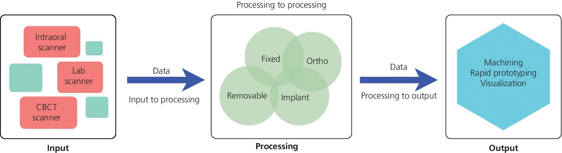
Figure 15.1 Digital prosthodontics platform flow of data.
For the data‐acquisition phase there is standardization of the digital radiographic data through the Digital Imaging and Communications in Medicine (DICOM). DICOM is a standard developed by American College of Radiology (ACR) and National Electrical Manufacturers Association (NEMA) for the handling, storing, printing, and transfer of information in medical imaging. However, for dental CAD/CAM systems, there is no equivalent standard. The industry has gravitated to using an STL (stereolithography) file format as a de facto standard. STL is a file format created by 3D Systems (3D Systems, Rock Hill, SC) in the 1970s; today it is also referred to as “Standard Triangulation Language” or “Standard Tessellation Language,” both misnomers, as it is not a true standard. Using this file format, the surface of a three‐dimensional (3‐D) object is defined by a series of triangles. A limitation of this file format in dentistry is that it has no representation of color or texture. The accuracy of representation of a curved surface is determined by the size and density of the triangles (Figure 15.2). In recognition of these limitations, other standard file formats are under development but as of yet have not been adopted. One such example is Additive Manufacturing File Format (AMF). This open source ISO/ASTM Standard 52915:2013 supports color, materials, lattices, and constellations.
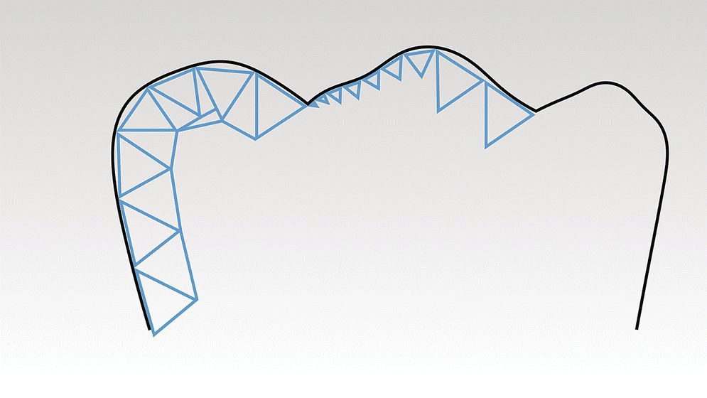
Figure 15.2 Three‐dimensional surface geometry as described by an STL (stereolithography) file. Black line is original tooth contour, blue line is STL model. Note how the size and density of the triangles will affect the trueness of the model to the original anatomy.
Technologies for implant diagnosis and treatment planning
The success of any prosthodontic treatment is predicated upon a sound diagnosis and treatment plan. Radiographic survey and mounted diagnostic casts form the foundation. Paramount to the evolving digital workflow for implant prosthodontics is the use of digital radiographs, whether planar films or three‐dimensionally reconstructed images (Figure 15.3). Digital radiography has been shown to result in decreased time and radiation dose for an equivalent diagnostic accuracy1–3 and image analysis time savings.4,5 Cone‐beam computed tomography (CBCT) allows for linear measurement, analysis of the 3‐D topography of potential implant sites, and determinations of proximity to critical anatomical structures (Figure 15.4). Ultimately, CBCT assists in the fabrication of implant surgical guides;6–9 however, deviations between planned and actual implant location have been noted, emphasizing the need for clinical care.6
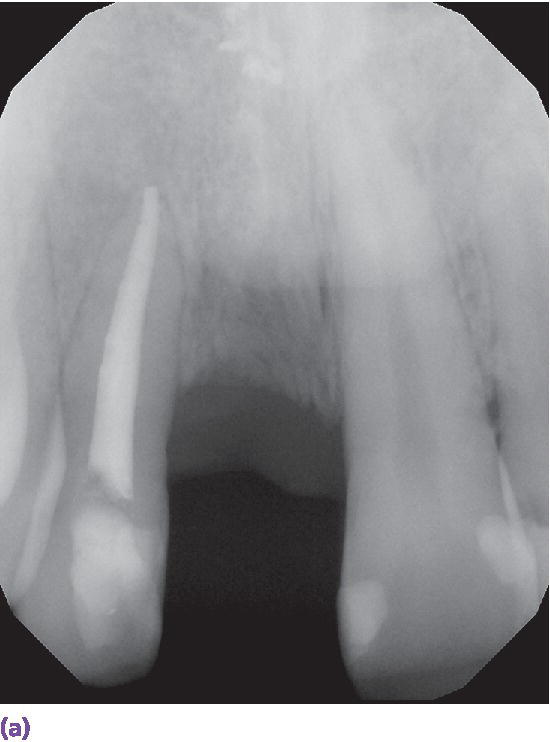
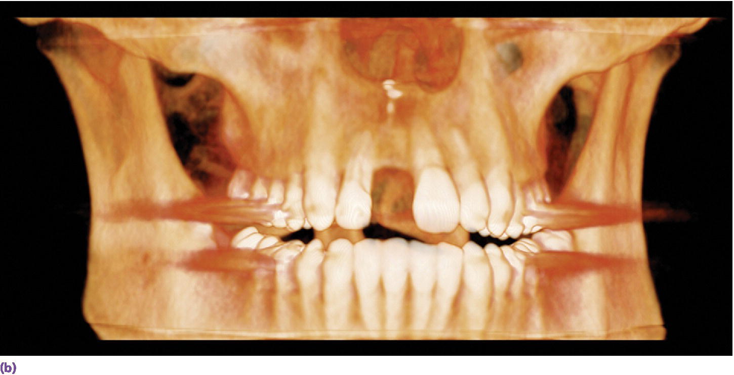
Figure 15.3 (a) Digital periapical radiograph of potential implant site. (b) Three‐dimensionally reconstructed CBCT image.
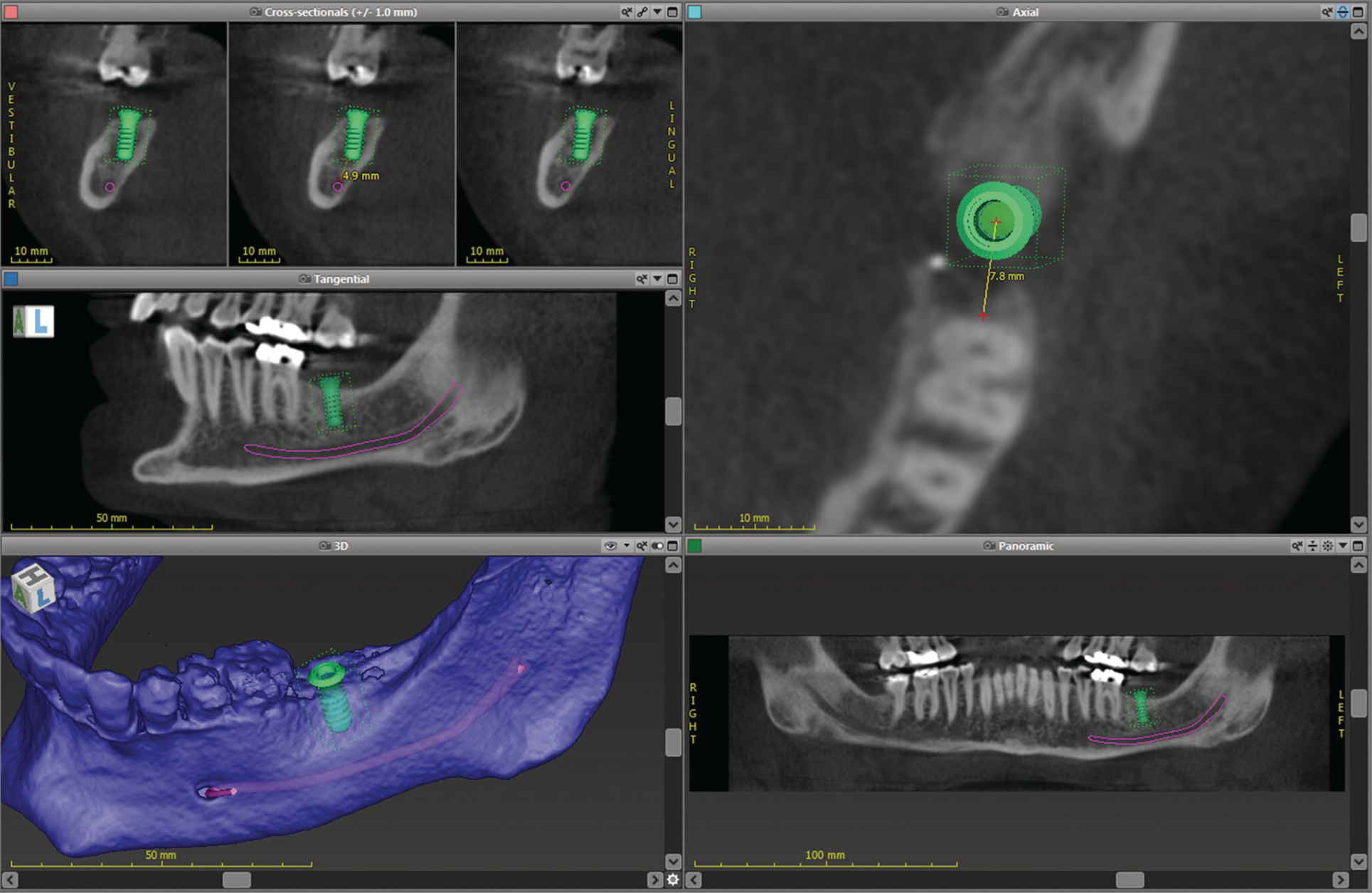
Figure 15.4 Implant‐planning software showing linear measurements, proximity to vital structures, and 3‐D surface topography.
Can the use of an intraoral scanner replace alginate and dental stone? Casts from an intraoral scanner can be produced through either a subtractive milling process or an additive 3D printing process (Figure 15.5). The Cadent iTero scanner (Align Technology, Inc., San Jose, CA) uses milled casts. Linear measurements of the mesial–distal, buccal–lingual, and occlusal–gingival dimensions of the digital models resulted in near‐perfect agreement (interclass correlation, 0.91–0.99) with caliper measurements on 60 dry skulls.10,11
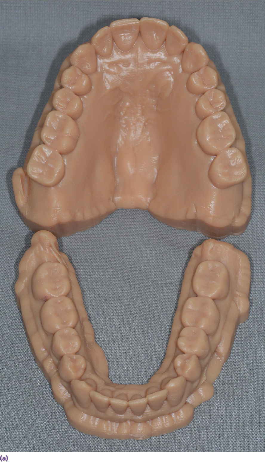
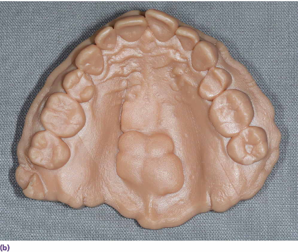
Figure 15.5 (a) An example of three‐dimensionally printed casts. (b) An example of three‐dimensionally printed maxillary cast with reproduction of maxillary torus.
The use of digital technologies has shown comparable results of pretreatment diagnostic wax‐up casts completed in a conventional wax‐up technique to those of a digital wax‐up in regard to axial tooth morphology (Figure 15.6).12
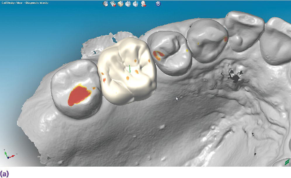
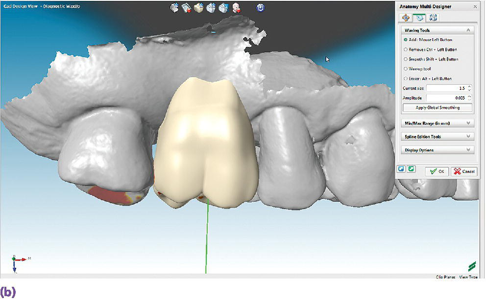
Figure 15.6 (a) A digital diagnostic wax‐up for a maxillary right first molar, occlusal view. (b) A digital diagnostic wax‐up for a maxillary right first molar, buccal view.
A third source of diagnostic data, not yet fully realized in implant prosthodontics, is the use of an extraoral 3‐D scanner (Figure 15.7). Not only are these devices able to capture static images but they can also be used to capture four‐dimensional images – the incorporation of real‐time motion of facial expression and features.13–15 The application of these four‐dimensional data sets in the diagnostic planning for the complex implant patient will allow for the virtual assessment of changes in vertical dimension of occlusion and facial esthetics as a result of prosthesis/tooth position. As of yet there is no software readily available to the clinician that incorporates the volumetric radiographic data, the intraoral scan data, and the extraoral four‐dimensional data.
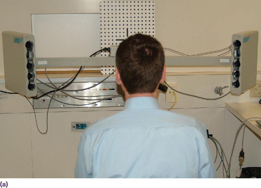
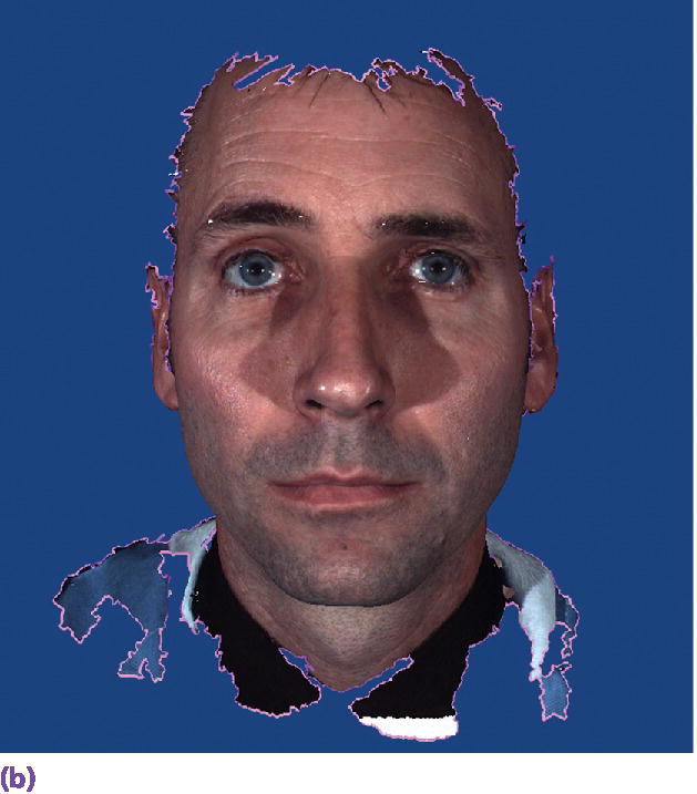
Figure 15.7 (a) Extraoral 3‐D camera set‐up. (b) Extraoral 3‐D facial image.
Technologies for implant placement
Although the use of surgical robotics is becoming more common in medicine, no such protocol exists for the routine use of surgical robotics for the placement of dental implants. The work on this in the dental arena is decidedly preliminary; however, initial studies have commenced with system validation and actual placement of implants.16,17
The more common approach is to use implant planning software such as NobelClinician® (Nobel Biocare, Yorba Linda, CA), SimPlant® (DENTSPLY Implants, Molndal, Sweden), coDiagnostiX™ (Dental Wings, Montreal, Canada), or Implant Studio™ (3Shape A/S, Copenhagen, Denmark). These software platforms allow the superimposition of CBCT data, intraoral scanner (or lab‐based cast scanner) data, and digital diagnostic plans of the final prosthesis for the planning of implant placement and the production of surgical guides.18–21 These guides can be produced using a subtractive process such as milling (Figure 15.8),22 or an additive process such as stereolithography or selective laser sintering.23,24 Recently, workflows have been developed for chairside dental CAD/CAM systems for milling of surgical guides in‐office.25–27 In vitro investigation has revealed an accuracy range of 0.17–1.3 mm for pilot drill preparation on stone casts for chairside‐milled CAD/CAM guides.28
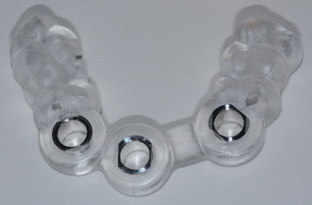
Figure 15.8 Milled implant surgical guide for a guided surgery protocol.
The use of CAD/CAM surgical guides is more accurate than a freehand approach for implant placement,29,30 and implants placed with the aid of a CAD/CAM surgical guide are positioned more accurately and with more consistent deviation from the planned location compared with those placed with conventional surgical guides.31 Comparing planned versus actual implant placement based on postoperative CT scans, the trend is toward tooth‐supported guides being more accurate with less deviation of implant position than mucosa‐supported guides.29,32–34 In vivo analysis of 111 implants placed in 24 patients revealed mean angular deviations of 1.72 ± 1.67° and 2.71 ± 2.58°, mean deviations in position of the implant neck of 0.27 ± 0.24 mm and 0.69 ± 0.66 mm, mean deviations in position at the implant apex of 0.37 ± 0.35 mm and 0.94 ± 0.75 mm, and mean depth deviations of 0.32 ± 0.32 mm and 0.51 ± 0.48 mm, for tooth‐ and mucosa‐supported stereolithographic guides, respectively (P < .05 for all).32 For mucosa‐supported guides, findings confirm that maximizing the supporting surface area and using rigid fixation improves the accuracy of implant placement. Additionally the reduced mucosal thickness of nonsmokers allows for less coronal and apical deviation of implant position as compared with smokers, and reduced bone density may affect accuracy negatively.35,36
In a study comparing implant surgical guides fabricated conventionally with acrylic resin, based on CBCT scan data only, or based on optical scan data, the fit of the conventional guides and those fabricated from the optical scan data had greater accuracy of fit than the guides fabricated from the CBCT scan.37 This is not unexpected due to the artifact scatter caused by metallic restorations, but also points to the potential for inaccuracies in the superimposition of intraoral scan data onto the CBCT data during implant planning. If such a malalignment has occurred, the planned implant placement will not be represented intraorally as the CAD/CAM guide is now positioned in a different 3‐D position than in the software. The clinician may still consider the value of a surgical guide try‐in with radiographs to confirm implant position and angulation, or, at a minimum, an initial scout radiograph at the time of implant surgery (Figure 15.9). The mean survival rate of implants placed using computer‐guided surgery with a follow‐up period of at least 12 months was 97.3% (n = 1941), which is comparable to implants placed following conventional procedures.38
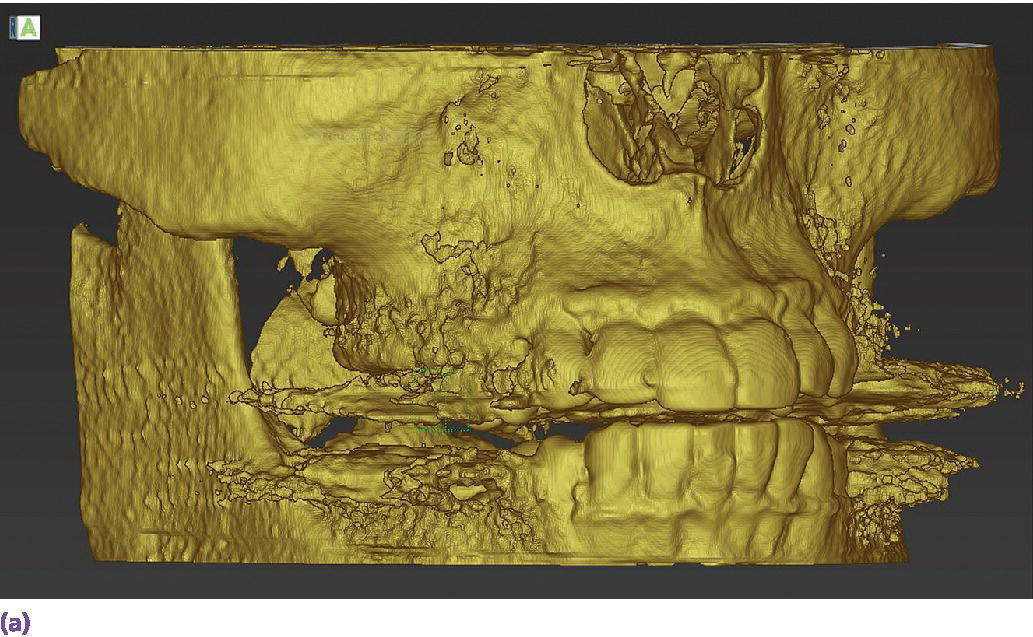
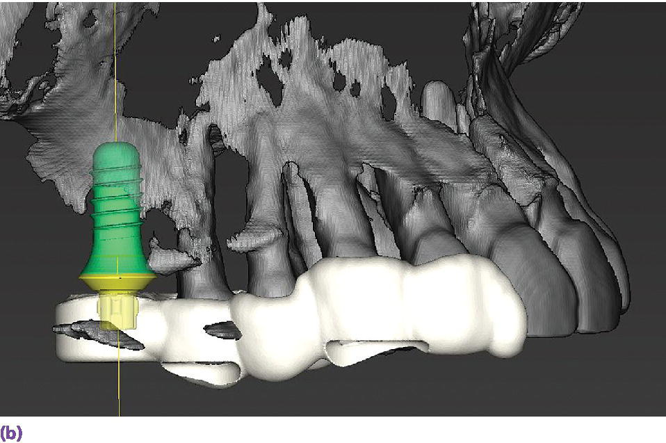
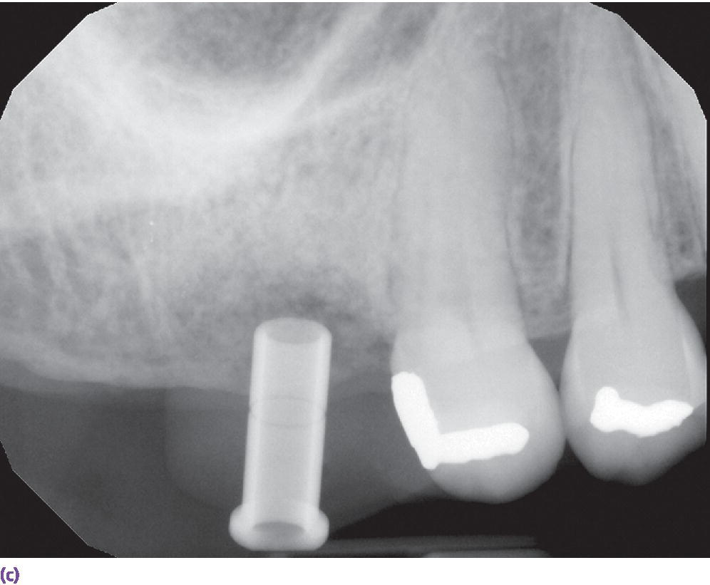
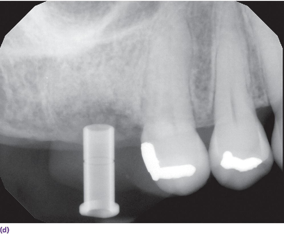
Figure 15.9 (a) Example of metallic artifact in CBCT data set. (b) Planned implant position for maxillary right first molar site. (c) Radiographic try‐in of milled surgical guide from digital implant plan showing angle deviation from original plan. This is most likely due to metallic artifact causing an inaccurate registration of the CBCT data set and the intraoral scan data set. (d) Corrected implant position and angulation after manual correction of surgical guide.
Technologies for implant interim prostheses
The rehabilitation of the implant patient may involve a period of time in which interim prostheses may be indicated. The use of the interim prosthesis is valuable in the validation of the diagnostic design,39–41 occlusal function,41 esthetics,39–42 contours,39–44 and patient phonetics41 that are ultimately duplicated in the definitive prosthesis.45–47 The interim prosthesis also allows for the monitoring of gingival tissue response and development of appropriate emergence profiles,44–46,48 allowing the gingival tissue to mature to the planned definitive prosthesis contours,42,49–51 all the while confirming osseointegration of the implant.51 This interim phase of treatment could be a relatively short period of time or could be quite lengthy, at which point the physical properties of the material become important (Figure 15.10).52
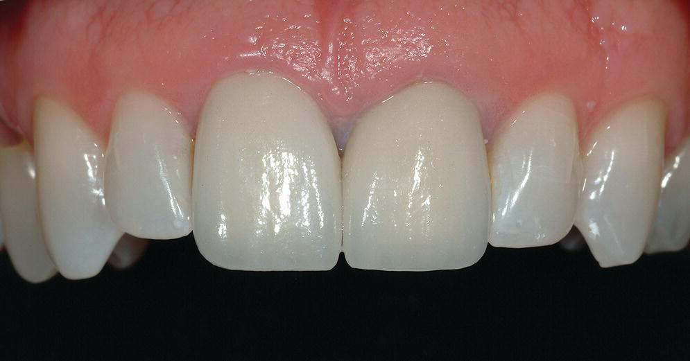
Figure 15.10 Long‐term milled CAD/CAM interim crowns for central incisor implants at the time of prosthesis delivery. Surface characterization and staining completed by hand.
An in vitro study of interim prosthesis materials for single‐unit interim premolar crowns demonstrated that CAD/CAM milled interim crowns from a polymethylmethacrylate material (Cercon Base PMMA blocks, DENTSPLY, York, PA) demonstrated enhanced color stability, higher mechanical properties, and better fit than the crowns made from a direct technique using autopolymerizing polymethylmethacrylate, automixing bis‐acryl compound, and thermoplastic highly crystalline acetal copolymer resins.53 Similar findings were reported for a study involving molar crowns, in which the two CAD/CAM materials, Vita Cad‐Temp (VITA North America, Yorba Linda, CA) and Telio CAD (Ivoclar Vivadent, Inc., Amherst, NY), demonstrated significantly less mean marginal gaps than the two direct‐fabrication materials, ProTemp 4 (3M ESPE, St. Paul, MN) and Structure 2 SC/QM (VOCO GmbH, Cuxhaven, Germany), both before and after thermal cycling.54 The authors also produced 25 × 2 × 2 mm bars from the four materials and subjected the specimens to three‐point bend tests both with and without thermal cycling. All groups exhibited significantly decreased flexural strength after thermal cycling, with the Telio CAD possessing the highest flexural strength. The authors concluded that CAD/CAM interim prostheses should be used for long‐term and long‐span clinical situations.54 In an investigation of interim fixed dental prostheses (FDPs), three‐unit FDPs milled from Telio CAD exhibited similar flexural strength to directly fabricated interim FDPs that were reinforced with a resin‐impregnated light‐polymerized glass fiber (GrandTEC, VOCO GmbH, Cuxhaven, Germany), which were significantly stronger than those fabricated without the reinforcing fiber.55
The digital implant workflow allows for the fabrication of interim abutments and prostheses prior to implant surgery.56 Through the use of CAD/CAM technologies, the cement margin can be optimally positioned in the sulcus to reduce soft tissue complications and maintain long‐term peri‐implant health.57,58 The role of crown contours, namely overcontouring, which could lead to bacterial biofilm accumulation and limits the patient and dental professional hygiene access, has been postulated as a potential cause of peri‐implant mucositis and peri‐implantitis.59 The authors go on to suggest that use of available 3‐D computer technology for implant prosthesis planning and design, along with enhanced communication among all members of the implant team, especially the dental technologists, may allow for a decreased incidence of peri‐implant disease.59
Technologies for definitive impressions
Although the focus of this chapter is on evolving technologies for implant prosthodontics, when it comes to the discussion of intraoral scanning for implants, much of the foundational data pertains to the use of intraoral scanners with natural teeth. It will be instructive to briefly review the natural tooth data that have established a baseline of accuracy and precision, allowing the expansion of scanning indications to include implant scanning. However, there are limitations unique to intraoral scanning of implants, especially with regard to large‐span edentulous regions.
Intraoral scanning for single‐tooth indications
In a unique clinical study involving three intraoral scanners and one lab‐based scanner that measured marginal gap using the established replica technique,60–65 the authors found the following marginal gaps: 88 μm (68–136 μm) [median/inter‐quartile range] for the True Definition (3 M ESPE, St. Paul, MN), 112 μm (94–149 μm) for the Heraeus Cara TRIOS (3Shape A/S, Copenhagen, Denmark), 113 μm (81–157 μm) for the laboratory scanner (3Shape D700, 3Shape A/S, Copenhagen, Denmark), and 149 μm (114–218 μm) for the CEREC AC Omnicam (Sirona Dental, Inc., Charlotte, NC). A statistically significant difference between the OmniCam group and all other groups (p < 0.05) was realized. The authors concluded that except for the one group, zirconia copings for single‐tooth restorations fabricated from intraoral scans and analog impressions combined with laboratory scans had comparable marginal fit.66
In summary, it has been demonstrated that intraoral scanning can produce single‐unit and multi‐unit dentate or implant prostheses of equal or better accuracy and precision of fit compared with prostheses fabricated from analog techniques.
Intraoral scanning for complete‐arch indications
Having earned a certain level of validity for single‐tooth intraoral scanning, the clinical indications may be expanded for impressions with the intraoral scanner. It is with these more complex clinical situations that differentiation between hardware and software may be realized. In an in vitro investigation that focused on the trueness and precision of four intraoral scanners used to scan a model arch with 14 units, the Lava COS (3M ESPE, St. Paul, MN) produced the most accurate results (trueness 38.0 ± 14.3 μm; precision 37.9 ± 19.1 μm) compared with the CEREC AC Bluecam (Sirona Dental, Inc., Charlotte, NC), which produced the least accurate results (trueness 332.9 ± 64.8 μm; precision 99.1 ± 37.4 μm). It was concluded that three of the tested systems – Lava COS, iTero, and Zfx IntraScan (Zfx GmbH, Dachau, Germany) – exhibited comparable results.67 The iTero datasets were converted to 3Shape (3Shape A/S, Copenhagen, Denmark) and Dental Wings (Dental Wings, Inc., Montreal, Canada) STL files. No differences were noted for the trueness of precision between the two software platforms (Figure 15.11).67
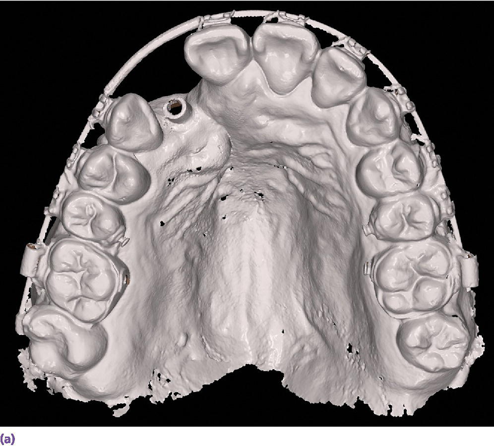
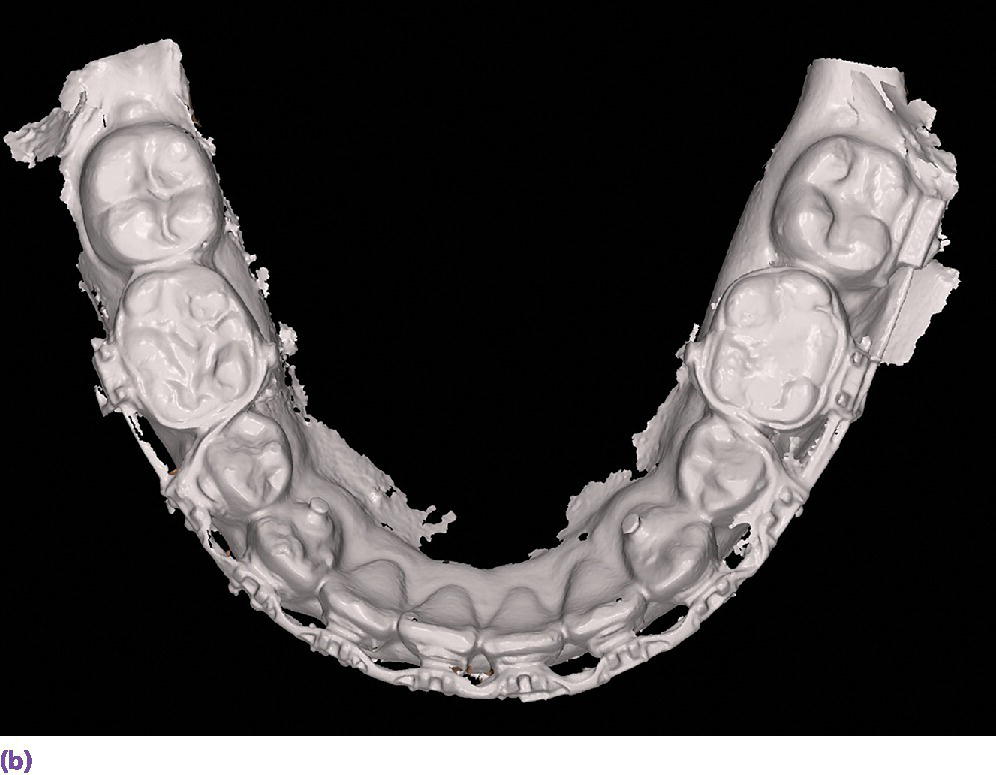
Figure 15.11 (a) Maxillary full‐arch digital diagnostic impression from an intraoral scanner. (b) Mandibular full‐arch digital diagnostic impression from an intraoral scanner.
Intraoral scanning for implant indications
To employ an intraoral scanner for the capture of an implant level impression, a surrogate means of registering the spatial 3‐D position of the implant and its rotational timing must be used. Currently, two fundamental approaches are applied. First is the use of a special healing abutment that is placed at the time of implant surgery; the second is the use of a scan body that is interfaced with the implant after the healing abutment has been removed.
The BellaTek® Encode® System (Zimmer Biomet, Warsaw, IN), launched in 200768 for conventional impressioning techniques, is one such system that uses unique patterns milled into the occlusal surface of the healing abutment that are used downstream to indicate the depth, rotational timing, platform diameter, and external versus internal connection type (Figure 15.12).69 Provided that there is no gingival overgrowth of the healing, this is a simplified clinical approach, as no removal of the healing abutment and placement of a unique scan body is required.70–72 However, it seems that the use of a coded healing abutment produces implant‐definitive casts that are less accurate than those produced from conventional open and closed tray techniques.73–75 More recently the coded healing abutment has been advocated with the use of intraoral scanners;76,77 however, no in vitro or in vivo data have been reported.
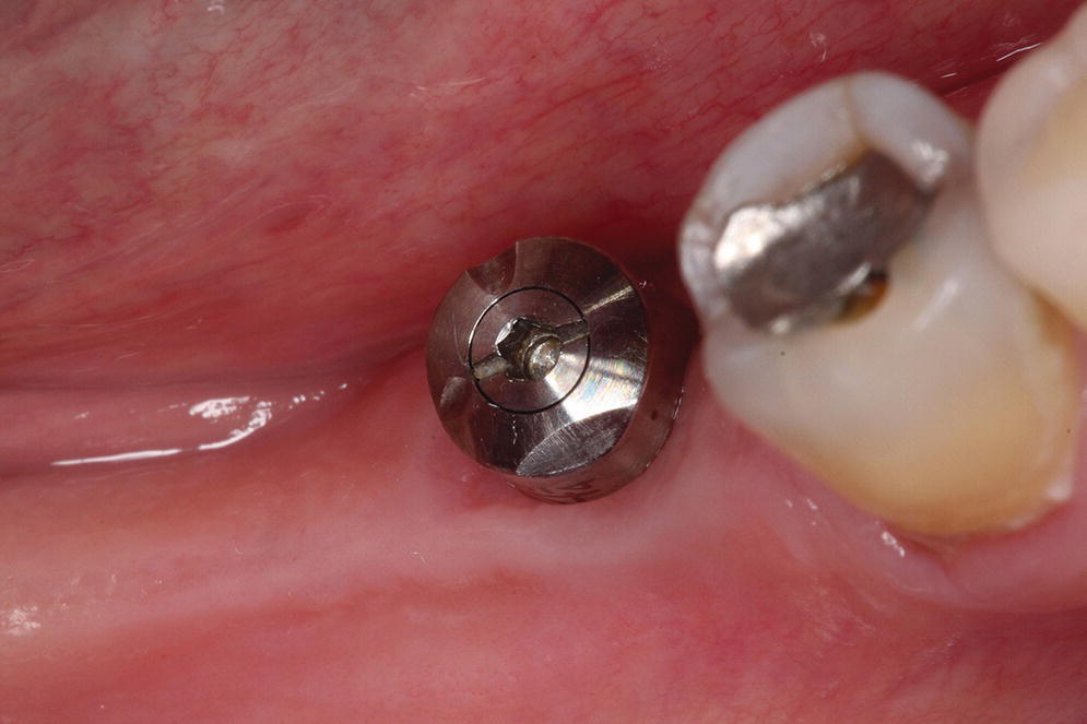
Figure 15.12 Specialized healing abutment with milled patterns to indicate implant depth, rotational timing, platform diameter, and external versus internal connection type.
Source: reproduced with permission from Dr. Abraham Stein, DMD, MS.
The more common and rapidly evolving method for intraoral scanning involves the use of unique scan bodies (Figure 15.13). These scan bodies can be procured from the original implant manufacturer or from a third party manufacturer. Through the application of the digital workflow, analog casts can be fabricated through either a milling or printing process (Figure 15.14). It has been shown that milled casts from data sets obtained from the iTero intraoral scanner are comparable to gypsum casts obtained from conventional impression materials. Variation was noted in the secondary anatomy features of grooves and fossae, with gypsum casts exhibiting more detail and prominent anatomy.78 It was noted that both gypsum and milled casts had a significant (P = 0.020) discrepancy in the vertical axis of the implant position as compared with the master model, with the gypsum casts having an apical position (–0.088 ± 0.044 mm) of the implant analog whereas the milled casts from the intraoral scanner had an occlusal position (0.093 ± 0.061 mm) of the implant analog compared with the master model.78 The clinical implication one might derive from this study is that implant crowns fabricated from either cast will have occlusal inaccuracies; those from gypsum casts would be in hyperocclusion and those fabricated from the milled cast in hypoocclusion clinically. Crowns in hypoocclusion would require a laboratory procedure to achieve occlusal harmony.
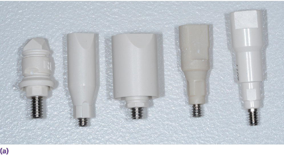
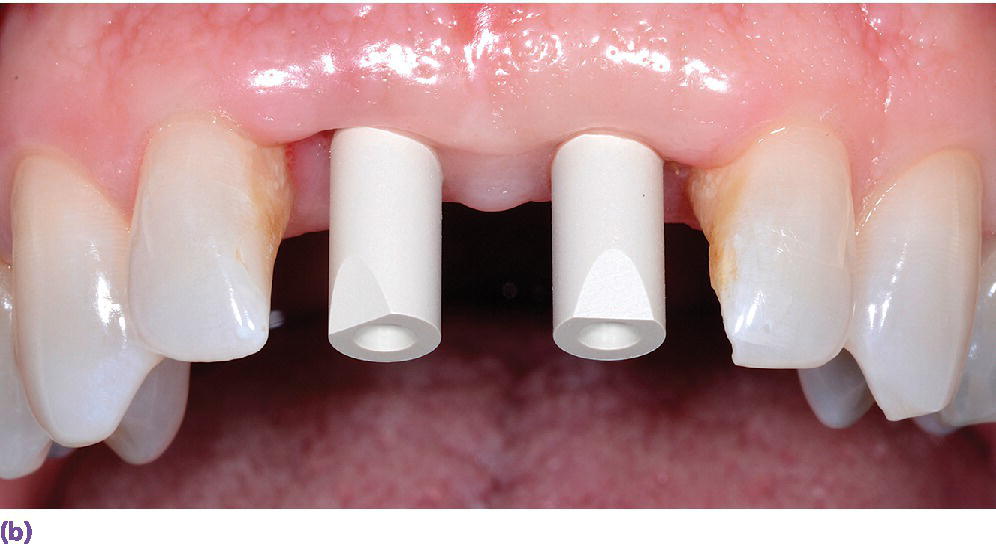
Figure 15.13 (a) Various scanbody geometries from different manufacturers. (b) Intraoral implant scanbodies for digital impressioning systems. Note the incisal bevel that must be oriented to the facial for proper CAD software registration.
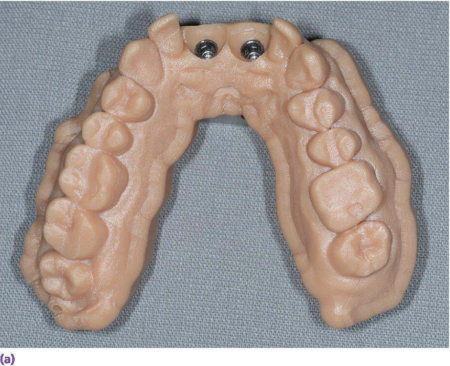
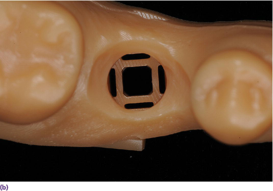
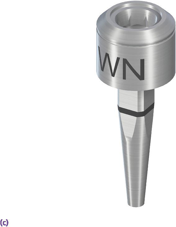
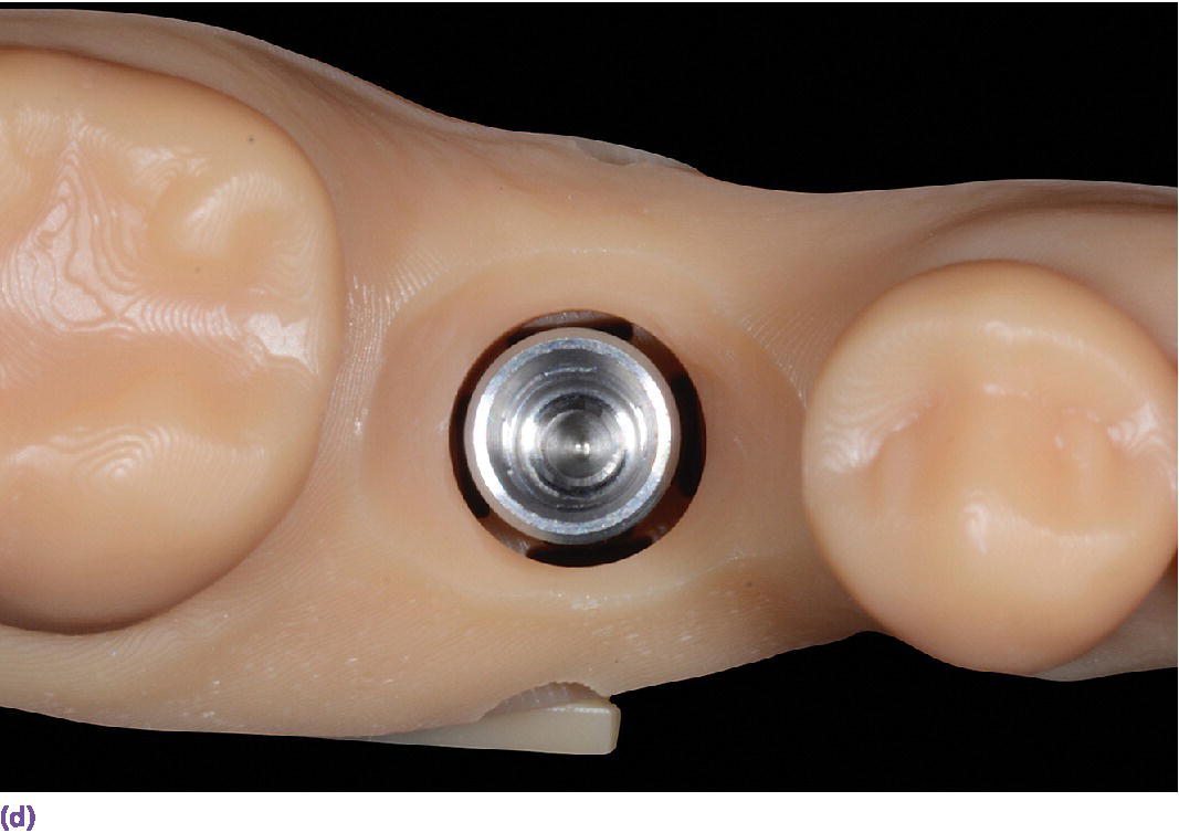
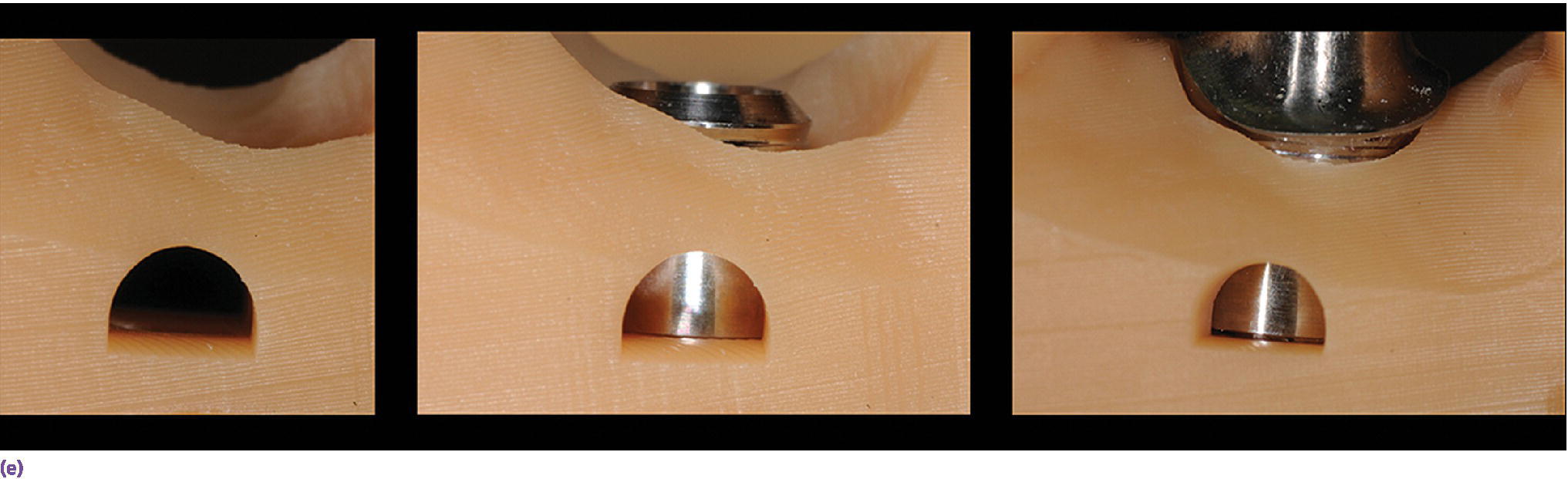
Figure 15.14 (a) Three‐dimensionally printed implant definitive cast. (b) Close‐up of the printed detail of the socket to receive the implant analog. (c) Implant analog for milled or printed casts. (d) Implant analog inserted into printed cast. (e) Verification window in printed casts to confirm complete seating of implant analog and/or abutment.
The accuracy of implant impressions generated from the use of intraoral scanners may be hardware/software dependent as well as clinical‐indication dependent. An investigation that involved complete‐arch scanning of a dentate model that had three reference scan bodies positioned in the mandibular first molar positions and right central incisor position realized differences in mean distance and angular errors among the three scanners tested. The scanner that used video capture technology and a high‐accuracy scanning protocol had smaller and more consistent errors compared with the two point‐and‐click scanners in regard to mean distance errors.79
Intraoral scanning for edentulous indications
Limited data exist pertaining to the use of intraoral scanners for edentulous arches. One in vitro study of four intraoral scanners (iTero, Lava COS, CEREC AC Bluecam, and Zfx IntraScan) used to digitize maxillary and mandibular edentulous reference models found mean trueness values ranging from 44.1–591.8 μm and mean precision values ranging from 21.6–698.0 μm. The greatest visual deviations of the superimposed data sets occurred in the maxillary arch, with digital mismatches in the palatal region.80 Although the Lava COS scanner achieved the highest level of accuracy in the study, the authors concluded that, because of the high degree of inaccuracy found in the study, the expectation was that even less accuracy would be realized due to saliva and mobile tissue intraorally. Therefore further enhancements were required before a clinical recommendation could be given to use these scanners for clinical edentulous arch scanning.80 New hardware and software have been released, but this study has not been replicated to validate manufacturer claims of the ability to scan soft tissues.
A unique in vivo study evaluated 25 patients who had mandibular bar overdentures fabricated previously. The original definitive master casts for each patient were digitized and served as the reference comparison for the intraoral scan data sets obtained with an iTero scanner.81 The authors concluded that the distance errors and the mean angular errors were too large to fabricate a well‐fitting superstructure for the two implants in the edentulous mandible. In fact, for four of the 25 patients, no clinically acceptable scan could be achieved. This was discussed as a limitation of the scanner technology and hardware. The intraoral scanner captures a maximum area of 14 × 18 mm.82 Stitching of the photographs was not possible if there was a large distance between the implants and a lack of definitive mucosal landmarks to function as reference points.81 However, some patients with large inter‐implant distances could be scanned because of the presence of stable mucosa that had adequately variable tissue height, allowing for appropriate reference for the software calculations.81 The authors demonstrated stitching errors in 10 of the 21 patients, four of the 21 patient scans exhibited deformation of the scan abutments, and one patient had both stitching and deformation errors. Five scans appeared to be optically correct; however, only one of those scans had acceptable errors (distance error of 60 μm and angle error of 0.342°).81 As discouraging as these results may seem, one must consider that at the time of the study this particular scanner was not indicated for this type of clinical situation; it has since gone through multiple software and, more recently, hardware updates. Highlighting the evolving nature of technology related to implant prosthodontics is important to assess the impact of new developments on the comparative accuracy with conventional techniques.
Intraoral scanning systems can be differentiated on the basis of whether or not an agent is required on the tissues to be scanned. The use of powder or other contrast media is required for different purposes, but in general is used to combat the challenges faced while scanning intraorally,83–85 and could prove beneficial in assisting the scanning of edentulous arches. The optical properties of the target surface, such as the translucency and reflectivity, vary between enamel, dentin, restorative materials, gingiva, and mucosa, and influence the accuracy of the scan. The geometry of the target surface, sharp line angles, and presence or lack of a supragingival margin are challenges for intraoral scanners, as are the moisture and humidity present in the oral cavity. Random relative motion can create artifacts in the dataset. The development of scan spray application has resulted in thinner coatings, enhanced image acquisition, and improvement in marginal fidelity of milled prostheses over conventional powdering techniques.85 The original CEREC Redcam and Bluecam (Sirona Dental, Inc., Charlotte, NC) required essentially a complete surface coating of the tissue in question, so that the projected striped light pattern could be reflected off the tissue surface and captured by the optical sensor. The 3M ESPE Lava COS and, more recently, True Definition scanners rely on the distinct macro‐features of the powder in the various images captured to allow aligning of the images in creating the 3‐D image (Figure 15.15). These contrast media typically consist of some combination of titanium dioxide, zirconium dioxide, and zinc stearate. The powder is used to reflect light and to minimize the scattering of the light off the target surface.86 These compounds are commonly found in food coloring and dyes. It has been shown that the neither the optical properties, composition, nor form of titanium and alumina oxides found in various contrast media had an impact on the marginal gaps of zirconia crowns fabricated using a lab‐based scanner.86 Similar results have been realized with infrared laser CEREC 3/RedCam and LED CEREC AC/BlueCam (Sirona Dental, Inc., Charlotte, NC) and different powdering techniques, as no differences were found on internal adaptation and marginal precision.87,88
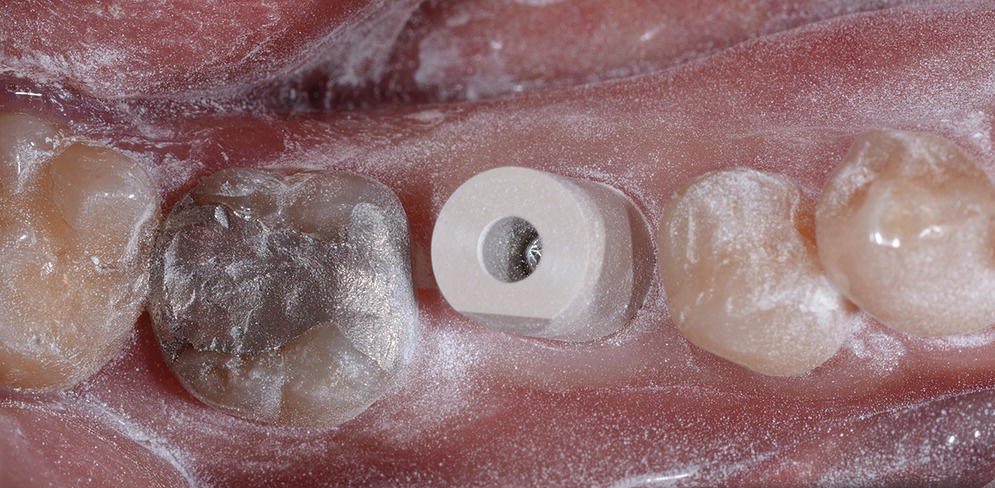
Figure 15.15 Proper isolation, field control, and contrast medium application for intraoral scanning of implant scanbodies.
The consistency of application of the contrast media has been shown to be operator dependent. An in vitro
Stay updated, free dental videos. Join our Telegram channel
VIDEdental - Online dental courses


