The purpose of this article was to report a procedure for using 3-dimensional cone-beam computed tomography imaging, computer-aided design, computer-aided manufacturing, and rapid prototyping to design and produce a retainer.
Advances in digital technology are vividly modeling our lives. The orthodontic specialty is no different; new technology has changed the way we practice orthodontics today. Coupling a digital replica of the teeth with the appropriate 3-dimensional (3D) software yields endless possibilities. The time when custom orthodontic appliances are made instantly by a simple procedure is coming closer.
The use of computer-aided design (CAD) and computer-aided manufacturing (CAM) techniques to design and fabricate an appliance has been reported in the orthodontic literature. Removable appliances, customized lingual brackets and archwires, orthodontic dental models, occlusal splints, and titanium Herbst, Andreasen, and sleep-apnea appliances have all been attempted.
The different techniques reported in the process of designing and fabricating an orthodontic appliance comprise similar basic phases. This first step commences with the acquisition of the digitized dental models. Various methods are available; however, laser scanning of the dental models is the gold standard for this acquisition. Next, 3D software is used to fabricate the orthodontic appliances virtually on the computer screen. Among the tools used for virtual construction of the appliance is the sophisticated construction phantom device arm. The virtual appliance is fabricated through either subtractive manufacturing technology or additive manufacturing technology. Subtractive manufacturing technology is the procedure of milling the appliance to the shape specified from a block of the desired material, and additive manufacturing technology adds material layer by layer until the 3D object is built.
Stereolithography is the additive manufacturing 3D printing technology. Three-dimensional printers are superior to subtractive technologies regarding cost, speed of manufacturing, quality, and the ability to fabricate complex structures that are not feasible with subtractive manufacturing technology.
The esthetic, retentive, and compliance advantages of the vacuum-formed Essix retainer are clearly stated in the orthodontic literature, and have made it among the first choices of retainers for postorthodontic retention.
In this article, we introduce a technique for integrating cone-beam computed tomography (CBCT), CAD/CAM, rapid prototyping, and additive manufacturing/stereolithography for designing and fabricating a retainer, using a simple, noncustom-made, commercially available 3D software.
Material and methods
The procedure starts with obtaining the digital replica of the patient’s teeth. After debonding, the patient’s dentition is scanned using CBCT (i-CAT; Imaging Sciences International, Hatfield, Pa); the area of interest (maxilla or mandible) is centralized in the machine’s focal trough. The patient is first instructed to bite on 2 or more tongue blades to separate the maxillary from the mandibular teeth. This ensures an easy and accurate separation of the dentition later on the 3D software.
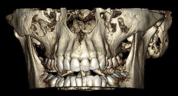
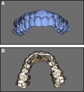
The CBCT data are exported in a DICOM format. The DICOM images are imported into the software (Invivo Dental; Anatomage, San Jose CA) ( Fig 1 ). The DICOM data are then used to generate a 3D model of the skull. The threshold desired is one that maximizes the visualization of the dentition while eliminating the soft tissue and any noise artifacts. Then the region of interest (maxillary or mandibular dentition) is cropped out of the whole 3D skull ( Fig 2 ); this is facilitated by the intermaxillary separation done during scanning. The 3D model for the area of interest is then exported as a .stl format file, which is later converted to .obj format.
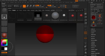
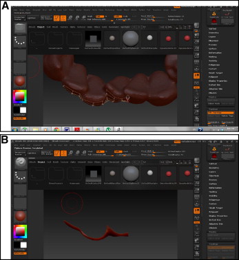
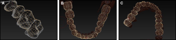
The data in .obj format are opened via another 3D handling software, ZBrush (version 4R4; Pixologic, Los Angeles, Calif). In ZBrush, the retopology concept is applied. Retopology is creating or modifying a new object on the surface of another object that accurately conforms to the old object. The ZSphere tool (Pixologic) ( Fig 3 ) is used to create a base mesh with clean topology. The ZSphere starts out with a simple sphere that one can extract from until obtaining the basic shape of the model to be sculpted on. The topology (surface contour) of the dentition is drawn via selection of points contoured to the surface of the teeth ( Fig 4 ). The points are placed on the teeth intended for the future retainer and according to the desired extensions needed to avoid soft-tissue impingement of the future retainer ( Fig 5 , A ). These points are connected to each other forming polygons ( Fig 5 , B and C ). An important criterion while placing the points is to preserve the symmetric geometry that allows creating a uniform mesh. The more symmetric and uniform (rectangular or square) the polygons are, the better the topology that is created, and the more uniform and accurate the mesh will be. No triangles or unsymmetrical polygons should be drawn. This topology forms the mesh or framework ( Fig 6 ), which is the foundation of the future virtual retainer.
Stay updated, free dental videos. Join our Telegram channel
VIDEdental - Online dental courses


