This report describes a novel concept of relocating orthodontic mini-implants during dental distalization to provide unrestricted distal movement of the full maxillary dentition. The patient was an 18-year old Korean woman with a full-step Class II Division 1 malocclusion and mandibular deficiency. Mini-implants were initially placed bilaterally between the maxillary second premolar and the first molar. Sliding jigs were used to distalize the maxillary first and second molars. After the maxillary molars were distalized to a Class I molar relationship, the mini-implants were removed and immediately relocated distally to provide space for retraction of the anterior teeth. The occlusion was completed with Class I molar and canine relationships with optimal overjet and overbite. The 2-year posttreatment records showed a stable treatment with retention.
Within the last decade, the use of mini-implants as temporary anchorage devices has greatly expanded the boundaries of orthodontic tooth movement. Individual teeth or an entire dental arch can now be moved accurately in 3 planes of space with minimal loss of anchorage. Many articles have discussed the different biomechanical designs integrating the concepts of mini-implants, risk factors associated with mini-implants, and parameters that can increase or decrease the stability of mini-implants. Mini-implants, if used properly, can serve as an alternative treatment option for patients who require orthognathic surgery by assisting in full-arch distalization or changing the occlusal plane with full-arch intrusion.
The treatment for patients with Class II Division 1 malocclusion and mild skeletal mandibular deficiency can be camouflaged by distalization of the entire maxillary dentition. Numerous designs for molar distalization appliances have been reported in the literature including the Hilgers pendulum appliance, the Cetlin headgear and removable appliance, the Jones jig distalization apparatus, and open nickel-titanium (NiTi) push coils. Most of these devices suffer from a loss of anterior anchorage and relapse after removal of the distalization appliance. Although the use of mini-implants to overcome these problems has been reported in the literature, separate and multiple mini-implants are usually necessary for successful distalization of the maxillary molars and retraction of the anterior teeth.
This case report describes a novel biomechanical technique for distalizing the entire maxillary dentition by relocating the mini-implants immediately after their removal. This technique helps to reduce the cost of using several mini-implants during treatment and expedites the overall orthodontic treatment progress.
Diagnosis and etiology
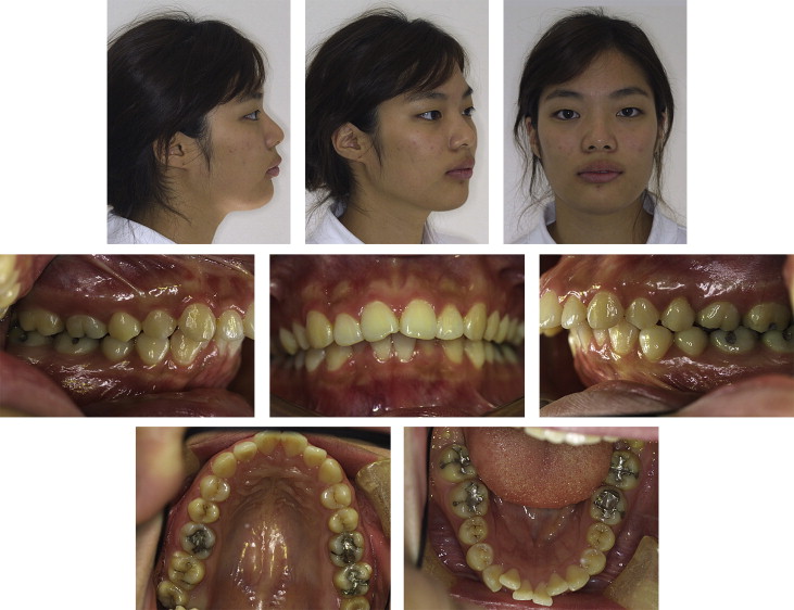
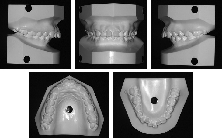
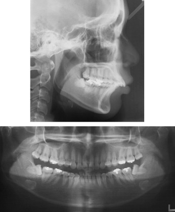
The patient was an 18-year-old Korean woman whose chief concern was “crooked front teeth.” The intraoral examination showed a full-step Class II Division 1 malocclusion with bidentoalveolar protrusion and moderate-to-severe crowding of the anterior teeth ( Figs 1 and 2 ). The cephalometric analysis showed a skeletal Class II pattern with an ANB angle of 5°, excessive proclination of the maxillary and mandibular incisors with a U1-NA angle of 36°, an L1-NB angle of 41°, and an interincisal angle of 98° ( Fig 3 , Table ).
| Female average ∗ | Pretreatment | Posttreatment | 2 years retention | |
|---|---|---|---|---|
| SNA (°) | 81.6 | 79.4 | 80.3 | 80.4 |
| SNB (°) | 79.2 | 74.5 | 74.9 | 74.3 |
| ANB (°) | 2.4 | 4.9 | 5.4 | 6.1 |
| PFH/AFH (%) | (66.8%) | 66.1 | 67.4 | 68.9 |
| SN-OP (°) | 17.9 | 16.5 | 20.5 | 19.3 |
| FH-UI (°) | 116.0 | 124.5 | 111.3 | 111.9 |
| FMA (°) | 24.3 | 24.4 | 22.5 | 20.4 |
| IMPA (°) | 95.9 | 113.1 | 110.3 | 111.8 |
| FMIA (°) | 59.8 | 42.5 | 47.2 | 47.8 |
| UL-E plane (mm) | –0.9 | 2.9 | 0.2 | –0.4 |
| LL-E plane (mm) | 0.6 | 3.1 | 0.2 | 0.2 |
| Interincisal angle (°) | 123.8 | 98.0 | 115.9 | 115.8 |
| Mx 1 to NA (mm) | 7.3 | 9.8 | 2.4 | 2.7 |
| Mx 1 to NA (°) | 25.3 | 35.8 | 21.7 | 22.0 |
| Mn 1 to NB (mm) | 7.9 | 9.1 | 7.25 | 7.8 |
| Mn 1 to NB (°) | 28.4 | 41.3 | 37.0 | 36.0 |
| SN to PP (°) | 10.2 | 6.4 | 6.1 | 5.7 |
∗ For Korean women, data from Korean Association of orthodontists.
Treatment objectives
The treatment objectives were to (1) camouflage the skeletal malocclusion by distalization of the entire maxillary arch, (2) correct the molar and canine relationships to Class I with mutually protected canine guidance, (3) achieve optimal overjet and overbite, and (4) improve the facial balance.
Treatment alternatives
Based on the above objectives, 2 treatment options were proposed. Both plans required the extraction of all third molars. The ideal treatment option involved the extraction of both maxillary and mandibular first premolars. However, the patient adamantly refused extraction of any permanent teeth. Therefore, the second treatment option was accepted by the patient; it required the use of temporary skeletal anchorage devices (mini-implants) to distalize the entire maxillary arch to correct the molar relationship, overjet, and overbite with extraction of only the third molars. The patient was also informed that this process would occur in several stages: (1) upright the mandibular posterior teeth and resolve the crowding of the mandibular incisors, (2) distalize the maxillary posterior teeth, (3) retract the maxillary anterior teeth, and (4) coordinate both arches to achieve ideal overbite and overjet in the final detailing.
Treatment progress
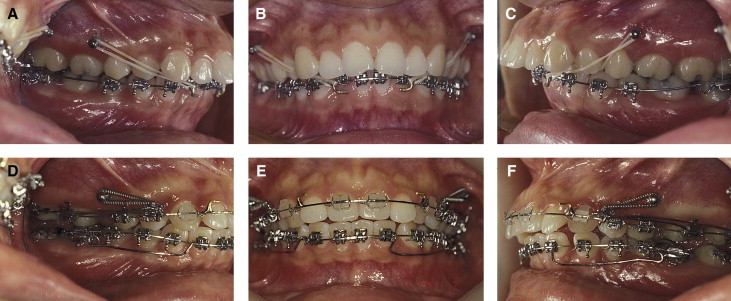
A 2-component mini-implant (diameter, 1.8 mm; length, 8.5 mm) (C-implant, CIMPLANT, Seoul, Korea) was placed bilaterally in the interradicular position between the maxillary second premolar and the first molar. The patient was then referred for removal of the third molars before the placement of the orthodontic appliances. Fixed appliances were first placed in the mandibular arch with omega loops mesial to the second molars to serve as stops in the tip-back mechanics. Mandibular molar uprighting began by using Class III elastics connecting the maxillary mini-implants to hooks soldered mesially to the mandibular canines on a 0.017 × 0.025-in mandibular stainless steel archwire ( Fig 4 , A-C ). The maxillary fixed appliance was then placed, and closed-coil NiTi springs were used bilaterally, connecting the mini-implant to a sliding jig for distalization of the maxillary first and second molars into a Class I molar relationship ( Fig 4 , D-F ). Concurrently, molar uprighting springs were used to continuously upright the mandibular molars by creating a coupling moment in bite-opening mechanics. The completion of this step generated a significant amount of interdental space between the second premolar and the first molar that would be used for retraction of the anterior dentition. The mini-implant was then relocated to a more distal position in the interradicular space between the maxillary right first and second molars and mesially to the maxillary left first molar.
The distalization technique started with placement of the mini-implants in the interradicular region between the maxillary first molars and second premolars. The maxillary molars were first distalized with either Class I intramaxillary elastics or NiTi closed-coil springs in combination with sliding jigs. After the maxillary molars were fully distalized into a Class I molar relationship, the need for relocation of the mini-implants to provide space for retraction of the anterior teeth was carefully evaluated. Periapical x-rays and panoramic radiographs or cone-beam computed tomography can be used to determine the availability of interradicular space between the maxillary first and second molars.
Local anesthesia was administered with approximately a quarter ampule of lidocaine (about 0.45 mL) near the initial mini-implant sites. The mini-implant head was removed by passing a dental explorer tip through the hole of the head and turning it in a counterclockwise direction ( Fig 5 , A ). After removal of the mini-implant head, the body of the mini-implant was manually unscrewed with a hand screwdriver ( Fig 5 , B ). The surface of the removed mini-implant was gently irrigated with saline solution, and the mini-implant was kept in a sterile isolation capsule. After mini-implant removal, a small cortical perforation was made at the new placement site by using a 1.5-mm diameter guide drill (Stryker Leibinger, Freiburg, Germany) at 1000 rpm ( Fig 5 , C ). When a small, continuous stream of blood was observed during the pilot drilling, the preparation for the placement of the mini-implant at the new location was considered complete. The clinician must ensure that the hex of the mini-implant body is always firmly engaged by the screwdriver to prevent disengagement of the mini-implant body while placing it in the new location. The diameter of the mini-implant body was 1.8 mm, and the mini-implant screw had self-tapping properties. Therefore, gentle but firm pressure with clockwise rotation of the screw was necessary during placement of the mini-implant in the new interradicular space ( Fig 5 , D-F ). No irrigation or suction is recommended during mini-implant placement, since maximum contact between the patient’s blood and the surface of the mini-implant seems to work more favorably in achieving stability of the mini-implant in the cortical bone. Another set of periapical radiographs was taken immediately after mini-implant placement to verify its successful relocation ( Fig 5 , G and H ). After verification, the mini-implant head was then gently tapped back into the mini-implant body with a small mallet. The newly placed mini-implants were immediately loaded by using Class I intramaxillary elastics with a force of approximately 150 g, connecting the mini-implants to the soldered hooks of the maxillary archwire mesially to the canines to initiate retraction of the maxillary anterior teeth ( Fig 5 , F ). Most clinical relocation procedures do not require antibiotic prophylaxis and high levels of analgesics.


