Introduction
The objective of this study was to demonstrate the potential of 3-dimensional modeling and finite element analysis as clinical tools in treatment planning for orthodontic tooth movement. High stresses in bone and miniscrew implants under load can cause fractures and trauma for orthodontic patients, and treatments are typically planned by using clinical experience or simple 2-dimensional radiographs.
Methods
Anatomically accurate 3-dimensional models reconstructed from cone-beam computed tomography scans were used to simulate the retraction of a single-rooted mandibular canine with a miniscrew placed as skeletal anchorage. Detailed stress distributions in the implant and peri-implant bone were found, in addition to the effect of the orthodontic bracket hook length and the angulation of retraction force on stress response in the periodontal ligament (PDL).
Results
The numeric results showed that the equivalent von Mises stress on the miniscrew under a 200-cN tangential load reached 42 MPa at the first thread recession, whereas von Mises stress in the peri-implant bone only reached 11 MPa below the neck. High tightening loads of 200 N·mm of torsion and 460 cN of axial compression resulted in much greater bone and implant von Mises stresses than tangential loading, exceeding the yield strengths of the titanium alloy and the cortical bone. Increasing the hook length on the orthodontic bracket effectively reduced the canine PDL stress from 80 kPa with no hook to 22 kPa with a hook 7 mm long. Angulating the force apically downward from 0° to 30° had a less significant effect on the PDL stress profile and initial canine deflection. The results suggest that stresses on miniscrew implants under load are sensitive to changes in diameter. Overtightening a miniscrew after placement might be a more likely cause of fracture failure and bone trauma than application of tangential orthodontic force. The reduction of stress along the PDL as a result of increasing the bracket hook length might account for steadier tooth translation by force application closer to the center of resistance of a single-rooted canine. The relatively minor effect of force angulation on the PDL response suggests that the vertical placement of miniscrews in keratinized or nonkeratinized tissue might not significantly affect orthodontic tooth movement.
Conclusions
This model can be adapted as a patient-specific clinical orthodontic tool for planning movement of 1 tooth or several teeth.
Anchorage is an important consideration for orthodontists and is often an essential component in treatment planning. Of particular clinical value is the situation in which absolute anchorage is required for retraction of anterior teeth or protraction of posterior teeth. Such anchorage can be provided extraorally with headgear or intraorally by using adjacent teeth or dental implants. The advantage of intraoral anchorage is reduced patient compliance for treatment. This is an important factor, considering that 19% of orthodontic visits in 2004 were by children under 12 years of age, and nearly 77% were by minors less than 18. Adults can also be averse to the use of headgear for esthetic or professional reasons.
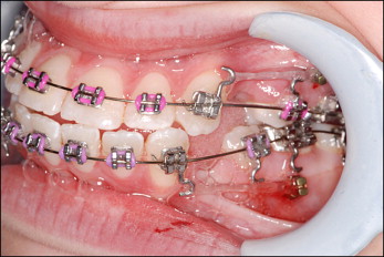
Temporary skeletal anchorage devices such as miniscrew implants have become increasingly popular in orthodontic tooth movement because of their biocompatibility, small size, and placement versatility. Figure 1 shows the placement of miniscrews between the roots of the mandibular second premolars and first permanent molars to retract the anterior canines without forward movement of the posterior molars. Miniscrews provide the option of early or immediate loading without a lengthy initial latency period. Other advantages include placement versatility because of the relatively small diameter of the endosseus body and relatively simple procedures for placement and removal. The smooth surface and minimal osseointegration reduce torsional resistance. Miniscrews can be placed between teeth with sufficient bone density and root clearance, giving orthodontists a variety of placement options. However, interference with the root or periodontal ligament (PDL) can cause significant anchorage loss and mobility or patient trauma. Heightened stresses in peri-implant bone from orthodontic loading, miniscrew orientation, surrounding bone quality and quantity, or miniscrew design might result in soft-tissue inflammation, microfractures in the bone or implant, or bone resorption. Such failures can compromise anchorage stability and increase the risk of pain or injury. Low stresses in bone at placement can also result in low primary stability of the implant or bone atrophy. High torque might also cause bone damage or miniscrew fracture, requiring corrective surgery.
Currently, the planning of miniscrew placement is limited to the use of clinical judgment in addition to 2-dimensional panoramic radiographs. The use of digital radiography can overcome some problems of image distortions resulting from magnification or image noise and reflections, but stress and strain distributions under orthodontic force application cannot be determined. Modern medical imaging, modeling, and finite element (FE) analysis solutions can provide powerful tools for optimizing 3-dimensional (3D) morphology from radiographic scans and determining stress and deflection distributions for complex anatomic geometries such as bone. Previous FE studies on miniscrews have used artificial, nonspecific bone-block geometries, finding critical stress areas and the effects of miniscrew length, diameter, and cortical bone thickness on stress response. Motoyoshi et al performed nonspecific simulations to test the effects of thread pitch and abutment attachment on miniscrew stresses. Pollei et al conducted FE analyses of miniscrews on various commercial implant designs with patient-specific bone geometry, defining a rigidly bonded implant-bone contact for linear simulation. Gracco et al performed nonspecific 2-dimensional FE simulations of a miniscrew with varying lengths and degrees of osseointegration, reporting that stresses decreased with greater osseointegration. Most FE studies focused solely on simulations with either miniscrews or teeth from different, isolated models. The objective of this study was to determine the stress profile on the miniscrew implant and peri-implant bone caused by both a tangential orthodontic force and tightening loads by using 3D modeling and FE analysis. In addition, the effects of orthodontic bracket hook length and force angulation on resulting stress response of the canine PDL were determined. The long-term goal was to determine the potential of 3D modeling and FE analysis in treatment planning for patient-specific tooth movements.
Material and methods
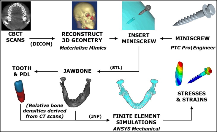
Figure 2 shows the procedures for 3D modeling and FE analysis in planning for patient-specific tooth movement with a miniscrew. First, a cone-beam computed tomography (CBCT) scan of a patient’s maxilla and mandible was acquired in vivo. Images with a square pixel size of 0.41 mm and a total size of 512 pixels per square were used. A total of 128 layered slices were saved in DICOM format with a 21-cm field of view and imported into Mimics software (version 12.1, Materialise, Plymouth, Mich). The voxel size was approximately 0.41 × 0.41 × 0.6 mm with a maximum smoothing error of half of this voxel volume. A global threshold was defined to isolate bone from soft tissues. Then automatic segmentation operations were performed on the morphology to reduce noise and artifacts. The mandibular left canine was isolated with its root for treatment by using local thresholding on the CBCT images. Scaling and Boolean operations were then carried out to model the PDL as a thin enclosure around the root with an average thickness of approximately 0.3 mm. Models were smoothed before the Boolean subtractions to ensure an even fit. One miniscrew implant design was chosen as anchorage for retraction of the mandibular canine and modeled with the ProEngineer Wildfire software (version 4.0, PTC, Needham, Mass). Dimensions and thread design were based on an implant (ACR OAS-T1207, BioMaterials Korea, La Mirada, Calif) with a thread diameter of 1.2 mm and a total length of 8.7 mm. This implant is constructed from Ti-6Al-4V titanium alloy for biocompatibility and designed for mandibular placement. The model was exported from ProEngineer in stereolithography format into the Mimics software and placed buccally approximately 1.4 cm down from the alveolar ridge between the first and second molars, normally to the cortical surface. Although possibly in unattached mucosa, which increases the risk of inflammation, this location eliminated interference of adjacent roots, and the objective of this study was to analyze detailed miniscrew stress behavior in patient-specific bone. This allowed us to cut out the bone block around the implant for separate simulation. The cortical layer at this location was also clearly defined in the CBCT images so that patient-specific geometric accuracy would be preserved. A subtraction operation was performed to create a matching drilled hole in the mandibular model. The reconstructed mandible, canine, PDL, and miniscrew were exported into the Mimics-Remesh module as stereolithography models. A volumetric mesh was then created and optimized by using tetrahedral elements. The optimized meshes of all models including mandible, miniscrew, PDL, and canine were exported from Mimics as ANSYS (version 11.0, ANSYS, Canonsburg, Pa) input files.
The model input files were read into ANSYS as volumetric element meshes by using 4-noded 6-degrees of freedom tetrahedral elements. Model coordinates and positioning of each component into the assembly were also saved. Four contact pairs ( Table I ) were created for each of the 4 interfaces: miniscrew-bone, PDL-tooth, PDL-bone, and tooth-bone. The PDL was glued to the canine root and the mandibular socket at the inner and outer surfaces, respectively, to prevent slippage or separation. Contact between the titanium-alloy miniscrew and the mandible was defined with a coefficient of friction equal to 0.37 as the average value reported by Mischler and Pax, whereas a coefficient of friction equal to 0.30 was assumed for any possible tooth-bone contact upon excessive PDL compression.
| Material | Elastic modulus E (GPa) |
Poisson’s ratio ν |
Yield strength (MPa) |
|---|---|---|---|
| Trabecular bone | 1.50 | 0.30 | 2 |
| Cortical bone | 14.7 | 0.30 | 133 |
| Tooth | 20.7 | 0.30 | — |
| Miniscrew (Ti6Al4V) | 114 | 0.34 | 880 |
| PDL (linear model) | 6.89 × 10 −5 | 0.45 | — |
After importing the models into ANSYS, the material properties were defined from literature references ( Table II ). All materials used in this study were defined as homogeneous, isotropic, and linearly elastic. Our value for the PDL’s elastic modulus was close to correctly documented values from original studies. The distribution of bone and tooth elements was determined in the Mimics software by the intensity or gray values of the CBCT scans reported in Hounsfield units (HU). With no loss of generality, the tooth was considered as a homogeneous material. Cortical bone elements were assigned according to an average value of 1400 to 2200 HU, and trabecular bone below 600 HU. These ranges fall within reported HU material limits for CBCT scans. Views of the final FE assembly with individual models and coordinates are shown in Figure 3 .
| Interface | Contact behavior |
|---|---|
| Miniscrew-bone | μ = 0.37 |
| PDL-tooth | Bonded |
| PDL-bone | Bonded |
| Tooth-bone | μ = 0.30 |
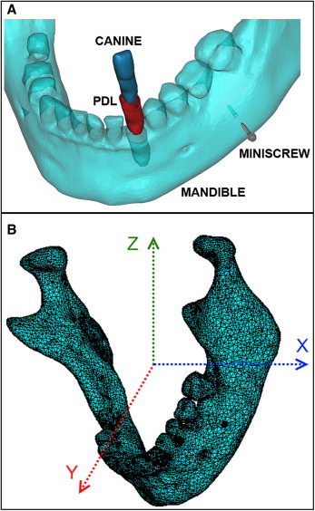
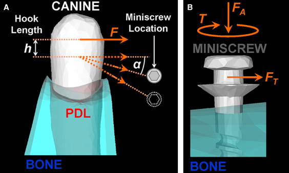
Figure 4 illustrates the simulated load cases of this study. A 200-cN tangential force was applied perpendicular to the miniscrew axis on a central node of the notch in accordance with the reported clinically safe limit for immediate loading. A compressive axial force of 460 cN and tightening torque of 200 N·mm were also applied on the miniscrew to simulate maximum placement loading measured experimentally. A 100-cN distal horizontal tipping force was applied in 50 load substeps on the buccal crown surface of the canine. The point of application of the distal force was varied down the long axis of the tooth to simulate the changing hook length. Angulation of the force was varied apically from the occlusal plane to simulate the changing vertical placement of the miniscrew and the angled line of action for an attached spring or elastic band. Nodes at the outer edges of the bone block were fixed to eliminate rigid body motion. Modeling the bone at a distance greater than 4.2 mm from the site of implant placement yields no significant increase in FE analysis accuracy in the implant region. The volumetric meshes of the miniscrew and the surrounding bone were refined near the interface, and stress profile paths were plotted down the length of the miniscrew from neck to tip, down the tooth, and along the inner PDL surface.
Results
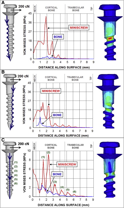
Figure 5 shows the equivalent von Mises stress in the miniscrew implant and surrounding bone under a 200-cN tangential force applied at a center node of the miniscrew notch parallel to the cortical bone surface. Implant stresses were plotted along the surface from the neck to the tip, and corresponding von Mises stress distribution contours are shown to the right of each graph. The greatest implant stresses appeared around the neck and at the smallest diameter cross-sections of the upper threads. The tension side of the miniscrew ( Fig 5 , A ) exhibited the highest stress magnitudes, with a maximum von Mises stress of 42 megapascals (MPa) concentrated in the recession of the first thread and steadily decaying farther down the implant. The peri-implant bone experienced considerably lower stresses on the tension side. Little stress appeared in the trabecular bone layer. The compression side of the miniscrew ( Fig 5 , B ) showed lower stress magnitudes and a broader stress distribution. The maximum von Mises stress of 26.5 MPa on the compression side appeared in the first thread. Bone stresses on the compression side were greater than on the tension side, with a distinct peak von Mises stress of 11 MPa above the first bony thread. On the shear side of the miniscrew ( Fig 5 , C ), the local maximum von Mises stresses in the implant can be clearly seen to correspond to the top 6 threads, with the maximum von Mises stress on this path appearing in the second thread recession. Bone stress on this path also showed smoothly decaying behavior.
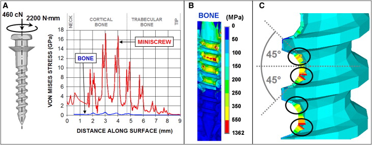
Relative to the tangential load, the miniscrew experienced much higher stresses under a torque of 200 N·mm and compressive axial force of 460 cN to simulate tightening loads ( Fig 6 ). Maximum von Mises stress in the miniscrew was about 17.3 GPa and appeared in the second thread ( Fig 6 , A ). Similar to the tangential loading miniscrew stress distribution, maximum von Mises stresses under tightening occurred at the top threads and decayed farther down the screw. The peri-implant bone carried a much lower portion of the total stress under the tightening loads than under the tangential loading, although stress magnitudes were significantly higher under tightening. Maximum bone stress approached 1.4 GPa ( Fig 6 , B ). The twin-peak behavior of the local maximum von Mises stresses in the implant shown in Figure 6 , A , corresponds to the implant surfaces oriented at 45°, as shown in the stress profile contour in Figure 6 , C . These surfaces correspond to the orientation of the principal planes for maximum compressive or tensile stresses.
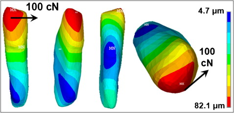
In the canine-PDL simulation, a 100-cN distal retraction force was applied at the middle of the buccal crown surface. The displacement distribution plotted in Figure 7 indicated crown-distal tipping and a slight twisting deflection of the canine. Maximum displacement of the tooth under this load was 82.1 μm at the top of the crown. The center of rotation can be seen by qualitative inspection around the top third of the root.
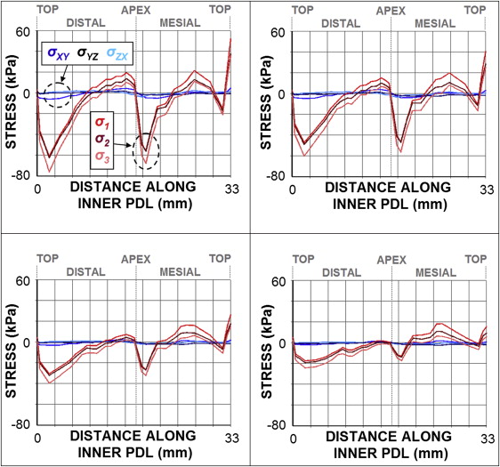
The changes in stress distributions in the PDL with variable bracket hook lengths are shown in Figure 8 . The graph was plotted along the inner PDL surface from the distal side to the mesial side with a distal force of 100 cN. The compressive and tensile regions can clearly be seen by the stress curves and correspond to crown-distal tipping, with compressive stresses showing higher magnitudes than tensile stresses. These stresses were much more pronounced than shear stresses. As the hook length (or vertical location of the force application point) was increased from 0 mm at the middle crown surface to 7 mm down the length of the canine, stress magnitudes in the PDL were significantly reduced along most regions. Tensile stress in the mesial PDL region remained relatively unchanged, although the stress magnitude was slightly reduced and spread over a larger area along the path. Maximum compressive stresses along the distal-mesial inner PDL path decreased from nearly 80 to 22 kPa when the hook length varied from 0 to 7 mm, respectively. Shear stress magnitudes were largely negligible in comparison.