Introduction
Archwire rotation is used in orthodontic treatment to alter the labiolingual orientation of a tooth. Measurement of the 3-dimensional (3D) motion of the orthodontic brackets requires a new configuration of the orthodontic torque simulator.
Methods
The orthodontic torque simulator was coupled with a stereo microscope and 2 cameras to allow for the 3D bracket motion to be determined during wire twisting. The stereo camera images were processed with a 3D digital image correlation technique to determine the 3D deformation of the orthodontic brackets. Three self-ligating brackets (Damon Q, Ormco, Orange, Calif; In-Ovation R, GAC, Bohemia, NY; and Speed, Strite Industries, Cambridge, Ontario, Canada) were compared by using the 3D digital image correlation method to demonstrate the difference in 3D motion of self-ligating brackets components.
Results
Contour plots of the 3 brackets demonstrate the 3D motion of the bracket tie-wings and the archwire retentive component. The 3D motion of the bracket tie-wings and archwire retentive component were quantified. The displacement values of the archwire retentive component measured with the 3D orthodontic torque simulator were found to be 2.0 and 3.5 times less for the In-Ovation and Damon Q brackets than the values in previous studies that examined the compliance of the archwire retentive component.
Conclusions
The 3D digital image correlation method used to quantify bracket deformation showed the 3D motion of the bracket tie-wings and the motion of the archwire retentive component. The use of a 3D optical measurement system is useful to understand the motion of the archwire retentive component but is not necessary to quantify bracket tie-wing motion. This measurement technique can be used to evaluate brackets of varying designs.
Archwire rotation is used in edgewise orthodontic treatment to alter the labiolingual orientation of a tooth by the interaction of a rectangular archwire and a bracket slot. Tooth movement is achieved through pressure applied to the tooth by the archwire. The resulting tooth movement depends highly on the magnitude of torsion applied through archwire rotation, the material properties of the archwire and the bracket, bracket and archwire geometry, and the location of the bracket on the tooth. These factors will affect the speed and efficacy of treatment, since torque applied to the archwire can result in permanent deformation of the bracket tie-wings. Permanent deformation to an orthodontic bracket will cause it not to function as expected; consequently, treatment time could be affected. Therefore, it is desirable to quantify the motion of bracket tie-wings caused by archwire rotation.
An orthodontic torque simulator was designed to simulate the clinical situation of archwire rotation and presented by Badawi et al. The orthodontic torque simulator was expanded upon through the development of an optical method of measuring bracket deformation by Lacoursiere et al. The optical bracket deformation method has indicated that the loads applied to an orthodontic bracket through archwire rotation can result in both plastic and elastic deformations. The optical bracket deformation method uses digital image correlation to determine the motion of the bracket tie-wings. Digital image correlation is a well-established optical measurement technique that has been widely used for both displacement and strain measurement. It has been applied in orthodontics to measure the shrinkage of resin-based dental composites. The optical bracket deformation measurement method developed by Lacoursiere et al has since been used to measure the deformation of both conventional brackets and self-ligating brackets.
The measurement of bracket–tie-wing deformation by using 1 camera is limited to measuring only 2 dimensions of the brackets. Major et al compared the 2-dimensional deformations of 3 self-ligating brackets and determined that In-Ovation R brackets (GAC, Bohemia, NY) plastically deform less than Speed (Strite Industries, Cambridge, Ontario, Canada) and Damon Q (Ormco, Orange, Calif) brackets for a maximum torquing angle of 63°. The maximum torque angle used by Major et al was well beyond the clinically relevant range. Orthodontic brackets and archwires move and interact in 3 dimensions; therefore, it is necessary to determine whether significant motion of the orthodontic brackets occurs in all 3 dimensions. The previous studies were limited to measuring only in-plane motion of orthodontic brackets; errors in bracket measurement could occur because of out-of-plane bracket motion. The addition of a second camera will allow the 3-dimensional (3D) motion of orthodontic brackets to be measured with a 3D digital image correlation technique to determine whether there is significant motion in all 3 directions. The ability to measure 3D deformation of orthodontic brackets will enable the archwire-bracket interaction to be fully described.
The addition of a second camera to the orthodontic torque simulator measurement system will also allow for the motion of the movable component used to secure the archwire of self-ligating brackets to be measured. The movable component used to secure the archwire is often referred to as a spring clip or a slide, depending on the bracket design, but for the remainder of this discussion the movable component will be called the archwire retentive component. Measurement of the archwire retentive component motion will allow for comparison of active and passive ligation brackets designs. Currently, the motion of the archwire retentive component has not been evaluated to determine whether compliance of active and passive ligation archwire retentive component designs can affect treatment. The goal of this study was to examine the deformation of self-ligating brackets in 3 dimensions by using the 3D digital image correlation version of the orthodontic torque simulator and the motion of the archwire retentive component.
Material and methods
A schematic of a tooth, self-ligating bracket, and archwire is shown in Figure 1 . Figure 1 , A and B , shows the coordinate system assigned to the bracket (x*, y*, z*) where the x* axis is defined as parallel to the archwire, the y* axis is the direction of lateral motion of the bracket tie-wings from archwire rotation, and the z* axis defines the direction from the base of the orthodontic bracket to the top of the bracket tie-wings. This coordinate system will be used to quantify the deformation that occurs to the bracket from archwire rotation. Archwire rotation occurs about the x* axis, and the angle of archwire rotation is defined as . The angle of archwire rotation, , is shown in Figure 1 , C . The neutral position of the archwire is when the archwire is parallel to the base of the bracket slot, shown in Figure 1 , C .
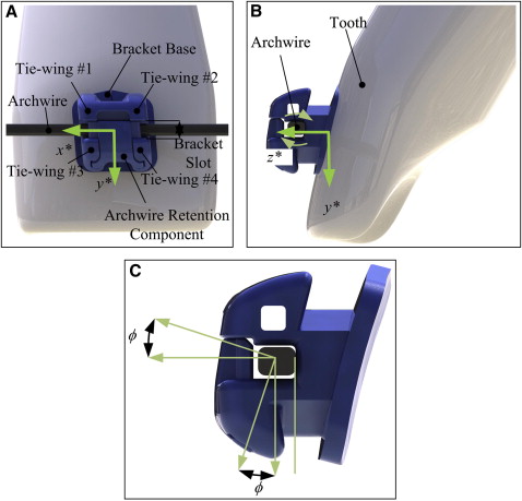
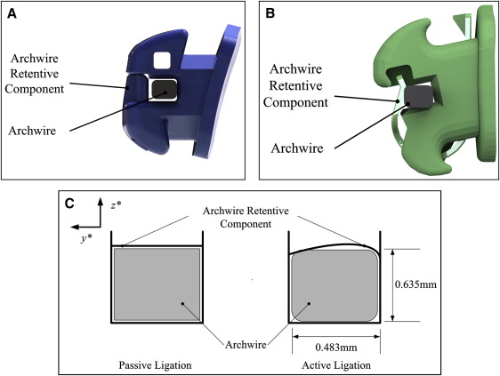
Archwires are maintained in the bracket slot by 3 main methods: elastomeric or steel ligatures, or self-ligating brackets. Self-ligating brackets are advantageous because the archwire can be ligated in the bracket slot more quickly than conventional elastic or steel ligation. Also, the archwire retentive component is not prone to degradation as elastic ligatures are because of the temperature and chemistry in the mouth. Active and passive self-ligating brackets will be compared by using the 3D orthodontic torque simulator to show the 3D motion of the bracket tie-wings and the motion of the archwire retentive component. Active ligation brackets are designed with a curved leaf spring type of archwire retentive component that encroaches in the bracket slot to maintain contact with and apply force to the archwire. Contact between the archwire and the archwire retentive component will help to maintain the alignment of the wire in the bracket slot. The curved leaf spring archwire retentive component is shown in the side images of the In-Ovation R and Speed brackets. Passive ligation brackets have a more rigid archwire retentive component that does not maintain contact with the archwire.
A comparison of active and passive ligation brackets is shown in Figure 2 . Figure 2 , A , shows the clearance between the archwire and the archwire retentive component for the Damon Q bracket; Figure 2 , B , shows that the archwire retentive component is in contact with the archwire for the In-Ovation R bracket.
The 3D deformation of orthodontic brackets was measured by using a modified version of the orthodontic torque simulator. Control of the orthodontic torque simulator stepper motor, acquisition of data from the load cell, and image acquisition are automated by using custom-designed software (LabWindows/CVI; National Instruments, Austin, Tex). The complete details of the orthodontic torque simulator design and the archwire rotation mechanism have been described.
The image acquisition system collects images of orthodontic brackets by using a stereo microscope (SteREO Discovery.V8; Carl Zeiss MicroImaging, Göttingen, Germany) with a 60-mm working distance objective lens (1.0X Zeiss V8 Plan Apo; Carl Zeiss MicroImaging). Images were collected by using 2 charge-coupled device cameras (Imager Intense, LaVision, Göttingen, Germany) at 1376 × 1040 pixels and 12-bit resolution. The cameras were connected to the stereo microscope with an intermediate phototube (Intermediate Phototube S 50:50 ports; Carl Zeiss MicroImaging). The brackets were imaged at 2.0 times magnification to maximize the bracket in the camera field of view. Test specimens were illuminated by using a ring light (2.64-in, variable frequency; Edmund Optics, Barrington, NJ) and a 365-nm black light (black replacement bulb, 365-nm peak; Edmund Optics) to provide even illumination across the field of view.
Images collected with the orthodontic torque simulator were acquired and postprocessed by using a commercial software package (StrainMaster 3D, DaVis 8.06; LaVision, Göttingen, Germany). Image subsets, or window size, used to determine the 3D displacement of the brackets were 64 × 64 pixels as a compromise between vector precision and maximization of the number of interrogation windows for each tie-wing. The field of view for the brackets was 1376 × 1040 pixels, or 4.25 × 3.2 mm; therefore, the resolution for this camera setup with a 64 × 64 subset size will be 0.07 μm. Digital image correlation displacement measurement comprises 4 consecutive steps: (1) specimen preparation, (2) calibration of the imaging system for a defined field-of-view, (3) collection of specimen deformation before and after loading, and (4) postprocessing of the images to determine displacement or strain. A specimen is prepared by applying a random pattern to the object surface. Images are calibrated to convert from pixels to physical space (eg, millimeters or inches) by acquiring an image of a target with a grid of known spacing. Each digital image is segmented into evenly spaced subsets, and an image correlation algorithm is performed for each image subset. Deformation is measured by tracking contrast features on the specimen surface between subsequent images. The displacement of a subset is determined by maximizing a cross-correlation equation for the images collected before and after deformation.
Orthodontic brackets were prepared before testing by coating the surface of the bracket with fluorescent airbrush paint (5404 fluorescent green; Createx Colors, East Granby, Conn). The paint was reduced at a ratio of approximately 2:1 to improve its flow through an airbrush (Wicked W100 Reducer; Createx Colors). Fluorescent paint was chosen for the speckle pattern to reduce reflection from the metallic bracket surfaces that can introduce errors in the digital image correlation processing. The use of an airbrush and fluorescent particles for digital image correlation was described by Berfield et al. Previously, bracket deformation measurements have used a microetcher to produce a random speckle pattern on the bracket surface, but fluorescent paint allows for a speckle pattern to be produced on the surface of the brackets without affecting its material properties.
Deformation of the bracket will be assessed by determining the relative motion between the 4 bracket tie-wings. The displacement vector fields generated by using the 3D digital image correlation software were further processed with a custom code to determine the motion of the bracket tie-wings and archwire retentive component (MATLAB; MathWorks, Natick, Mass). Equation 1 details the calculation of the bracket displacement in the x*, y*, and z* directions. In this equation, ¯DTieWing
D T i e W i n g ¯
denotes the average displacement of the defined regions for tie-wings 1, 2, 3, and 4 for the i = x*, y*, and z* directions. LHSD is the displacement between tie-wings 1 and 3, and RHSD is the displacement between tie-wings 2 and 4.
L H S D i = [ D T i e W i n g 1 ¯ − D T i e W i n g 3 ¯ ] i R H S D i = [ D T i e W i n g 2 ¯ − D T i e W i n g 4 ¯ ] i
Stay updated, free dental videos. Join our Telegram channel
VIDEdental - Online dental courses


