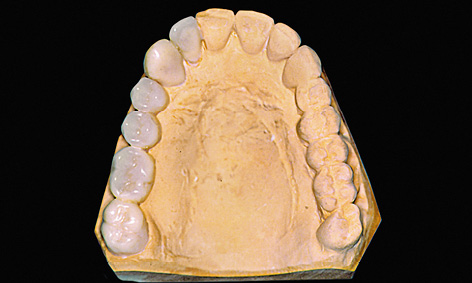
Fig 5-1b Teeth set up onto the cast.
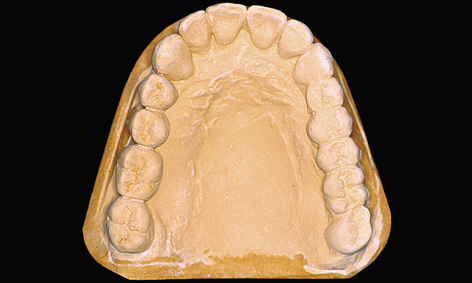
Fig 5-1c The duplicated cast.
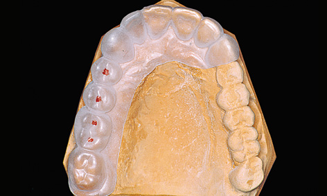
Fig 5-1d Thermoplastic foil on the starting casts with implant positions marked.
Even at the diagnostic stage, the factors that take priority in the posterior maxilla differ from those in the anterior maxilla. The esthetic component plays an important role here also, but the main focus is on the available bone supply and its quality. Typically, the loss of teeth brings with it a reduction in the bone bed, so that implant-based restorations of larger gaps or free-end situations are often possible only with the aid of augmentative measures. Single dental implant placement tends to be a rarity in the posterior maxilla; consequently, it will only be given brief consideration here. The failure risk of single implant placement is higher in the molar region, as the bone here is usually softer and subjected to greater physical forces than in the anterior maxilla.
Diagnosis
Conventional diagnosis
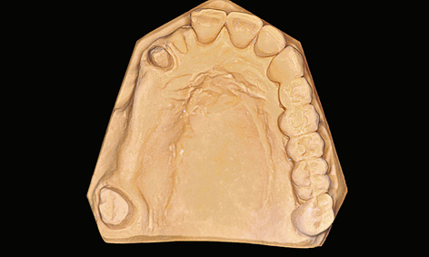
The diagnostic stages involved in a multi-tooth gap and a free-end situation are virtually identical. For prosthetic reasons, the implants should be inserted exactly where the natural teeth were originally located, or would have been located in the ideal-case scenario. These positions are reconstructed by setting up prosthetic teeth onto the maxillary cast in articulation (Figs 5-1a and 5-1b). If ground-down abutment teeth are present, these must also be waxed up (Fig 5-1b).
Fabrication of a radiologic or surgical template
A surgical drill template is constructed from a transparent plastic to allow the implant positions as determined on the cast to be accurately transposed to the patient. Initially, the wax-up needs to be duplicated in plaster, so that a template base can be fabricated using a thermoplastic foil (Figs 5-1c and 5-1d); otherwise, the wax-up would be altered by the heat in the deep-drawing device. The desired implant positions are marked in with a marker pen (Fig 5-1d). The marked sites are drilled and the parallelization pins attached to both the cast and the thermoplastic foil in accordance with the desired implant axes (Fig 5-1e). The pins must be so securely attached to the cast that they remain aligned exactly as required when the thermoplastic foil is removed (Fig 5-1f). Titanium sleeves are incorporated into the template at the specified positions to allow the planned implant sites to be identified in the radiograph. The sleeves are placed onto the parallelization pins, so that the channel of the sleeve reproduces the ideal implant position (Fig 5-1f). Generous openings are cut into the occlusal side of the thermoplastic foil and the latter is placed on the model (Fig 5-1g). The spaces thus created are filled with cold-curing polymer, securely anchoring the titanium sleeves in the template. The resultant template is worked up for the radiologic diagnosis (Fig 5-1h). A panoramic radiograph is taken or a cone beam computed tomography (CBCT) scan prepared with the template (Fig 5-1i). Since the sleeves are made out of titanium rather than steel, the template can also be used for a CT scan.
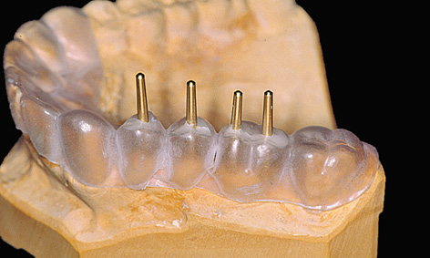
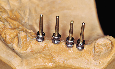
Fig 5-1f Titanium sleeves placed onto the pins.
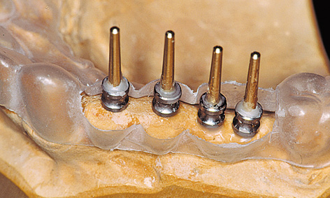
Fig 5-1g Thermoplastic foil with the occlusal surface reamed away.
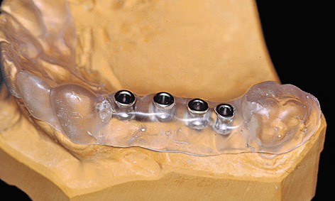
Fig 5-1h Titanium sleeves polymerized into the template.
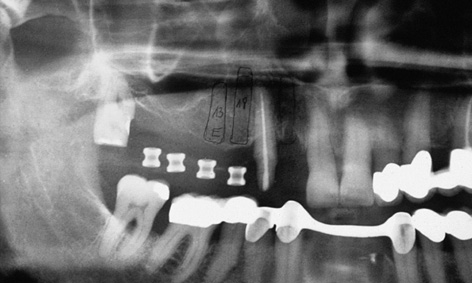
Fig 5-1i Panoramic radiograph with the template.
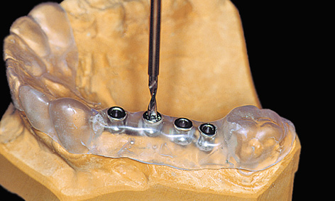
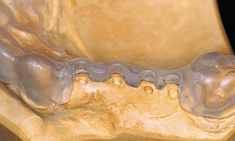
Fig 5-1k The template following removal of the titanium sleeves.
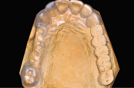
Fig 5-1l Completed surgical template.
The inserted sleeves restrict the drilling to a specific course (Fig 5-1j). However, the sleeves can be removed to allow a change in angle if the bone situation is unfavorable (Fig 5-1k). The entire buccal wall of the template should also be removed to give a better view of the operation area. The desired implant positions are still clearly determined by the notches in the palatal part of the template. During the course of implant placement, a template prepared in this way (Fig 5-1l) can be disinfected with, eg, alcohol or chlorhexidine, but must not be sterilized in the autoclave under any circumstances due to the risk of deformation.
For the treatment course, see page 327.
Note
Shaping the surgical template
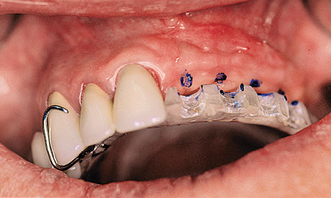
Fig 5-2a Stabilizing the template with a denture clasp.
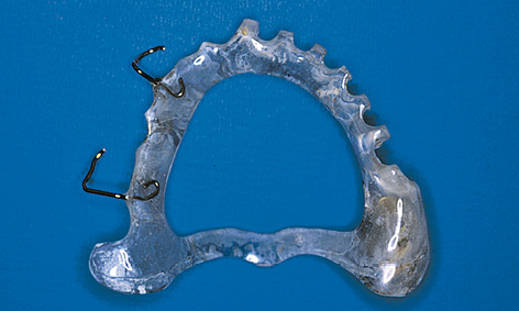
Fig 5-2b The palatal part of the template has been cut out.
The template can be anchored by supporting it on the incisal or occlusal surfaces of the remaining dentition. It is also possible to fasten the surgical template to the teeth with clasps, like a denture (Fig 5-2a). In cases of more extensive tooth loss, rests on the maxillary tuberosities and a transpalatal arch can help stabilize the template (Fig 5-2b). If a buccal incision is planned, space must be made for the palatal flap to be created, which requires the palatal part of the template to be cut out generously (Fig 5-2b).
Three-dimensional (3D) diagnosis in the posterior maxilla is already of significance in the overall treatment plan. The first decision to be made is whether direct implant placement is possible or whether the bone bed must be augmented first (sinus floor elevation). In the latter case, two CT scans and two sets of 3D planning are likely to be needed: one of each before sinus elevation and one after the bone has been augmented, but before implant placement. In the case presented here, we concentrate on the implant planning following preparation of the bone bed, ie, after sinus elevation (Fig 5-3a). The extent of the augmentation is clearly apparent in the panoramic section (Fig 5-3b). The detailed planning for each individual implant begins on the cross-sectional images (Fig 5-3c). In this projection, the proposed implant is placed into the maxilla virtually, either as a solid image or in outline (Fig 5-3d). On the other hand, the placement and distribution of all the implants can be seen best in the panoramic section (Fig 5-3e). The planned positions of all the implants are then checked in other planes and projection over the entire image surface area (Fig 5-3f). The 3D reconstruction provides the most vivid visualization and is best suited for the patient information procedure (Fig 5-3g). For the purposes of accurate analysis and documentation, the bone quality around each individual implant should also be determined by bone densitometry (Figs 5-3h to 5-3l). Implant 1 (region 23) is to be anchored in the existing local bone and shows the highest density values in the central region (Fig 5-3h). As an approximation, implant 2 (region 24) is to be anchored half in existing and half in augmented bone (Fig 5-3i). The difference between existing local bone and the bone substitute Bio-Oss (Geistlich) in the sinus floor elevation area becomes even more marked around implant 3 (region 25; Fig 5-3j). According to the available calculations, the augmented new bone, rich in Bio-Oss, shows much higher bone density than the autologous bone. Implants 4 and 5 (regions 26 and 27) also show a continuing decrease in the quality of both local and augmented bone in the distal direction (Figs 5-3k and 5-3l). This tendency toward a distal decrease in bone density is confirmed clinically in most cases while the implant beds are being prepared.
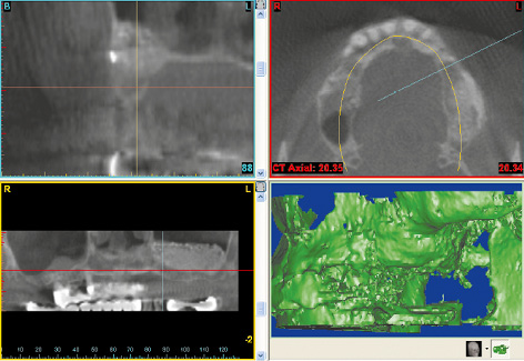
Fig 5-3a CBCT scan after the sinus floor elevation.
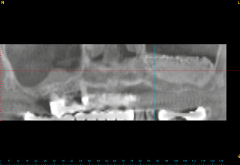
Fig 5-3b Left-sided sinus floor elevation in the panoramic section.
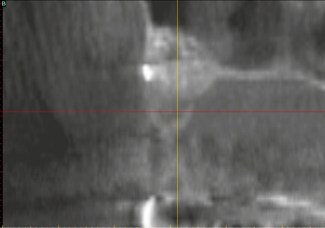
Fig 5-3c Cross section of the maxilla in region 24.
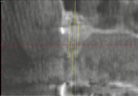
Fig 5-3d Outline of implant 24.
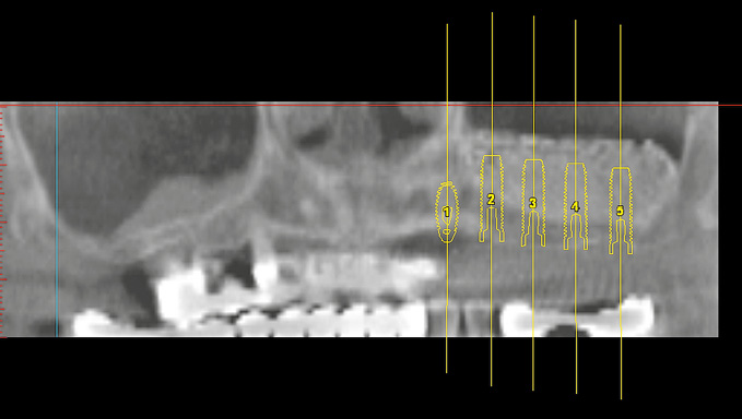
Fig 5-3e Distribution of the implants in the panoramic section.
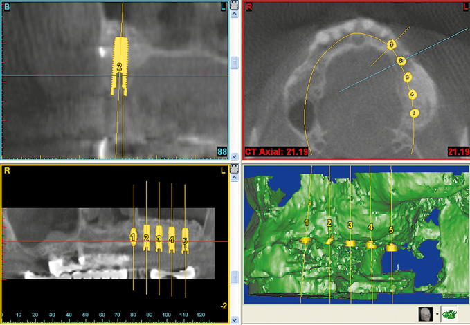
Fig 5-3f Overall planning in all the imaging planes.
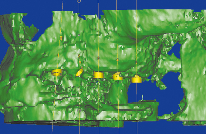
Fig 5-3g Vivid 3D reconstruction.
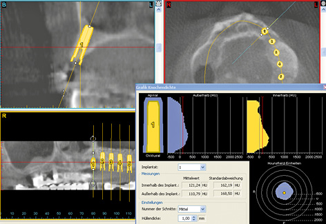
Fig 5-3h Bone densitometry around region 23.
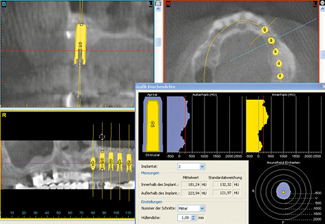
Fig 5-3i Bone densitometry around region 24.
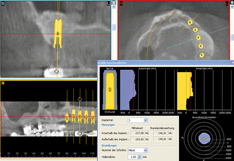
Fig 5-3j Bone densitometry around region 25.
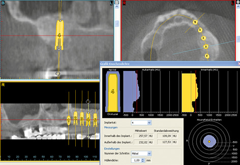
Fig 5-3k Bone densitometry around region 26.
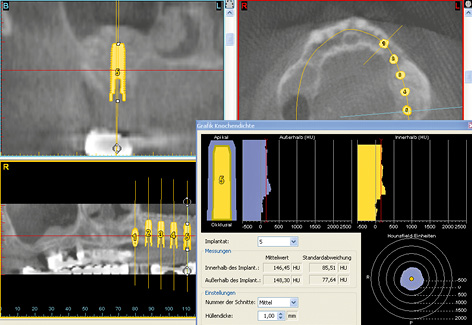
Fig 5-3l Bone densitometry around region 27.
For the treatment course, see page 378.
Restoration of single- and multi-tooth gaps
Typical treatment course
Fixed bridge with multiple abutments
The case report presented here is a continuation of the standard diagnostic investigations on pages 320–322.
Baseline situation
This female patient was to be provided with permanent replacements for teeth 12, 14, 15, 16 and 17. Her bridge 13 to 18 had a doubtful prognosis due to the root canal treatment on the canine and the periodontal weakening around the wisdom tooth (Fig 5-4a). In the edentulous segments – particularly distally – the residual ridge had already undergone extensive atrophy (Fig 5-4b). The panoramic radiograph showed that there was sufficient vertical space for implants 12, 14 and 15 (see Diagnosis on page 321; Fig 5-1i). Implant placement in regions 16 and 17 would require prior sinus floor elevation.
Diagnostic tools
- Clinical examination
- Panoramic radiograph
- Dental cast analysis
- Template
Treatment plan
1.Implant placement
2.Exposure
3.Definitive prosthetic loading
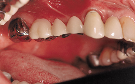
Fig 5-4a Fixed bridge 13 to 18 is to be reconstructed.
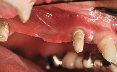
Fig 5-4b Situation following removal of the bridge.
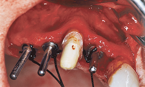
Fig 5-4c Direction indicators show the axes of the implants.
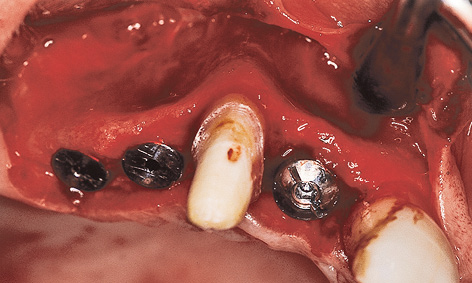
Fig 5-4d Inserted implants.
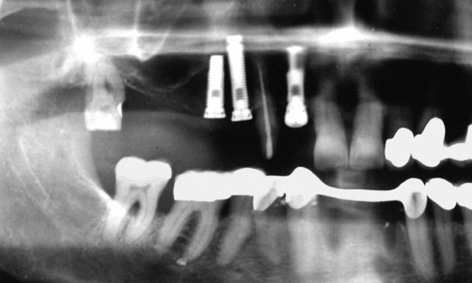
Fig 5-4e Three implant types to ensure optimal anchorage, dependent on bone quality.
Implant placement
Since the patient did not agree to a sinus floor elevation due to the increased operation time and complexity and the prolonged healing time, it was necessary to find a compromise solution. Positions 12, 14 and 15 were chosen for implant placement. The implant axes were adjusted to the anatomical situation (especially the implant in region 15; Fig 5-4c). Implants 14 and 15 were fitted with cover screws; implant 12 was fitted with a healing abutment for better mucosal support (Fig 5-4d). The postoperative radiograph shows three different implant types (Fig 5-4e). In region 12, where the bone was at its hardest, a self-tapping Brånemark System MK II fixture (15-mm long, 3.75 mm in diameter) was inserted to extend into the cortical bone of the floor of the nasal cavity. In region 14, where the bone was somewhat softer, a standard fixture (18-mm long, 3.75-mm in diameter) was placed parallel to the canine and inserted, without prior thread-cutting, to extend into the cortical bone of the floor of the maxillary sinus. The Brånemark System MK IV fixture has been developed especially for soft bone. It is slightly conical in shape (apical diameter 3.75 mm, coronal diameter 4 mm), has a double thread and thus provides very high primary stability.
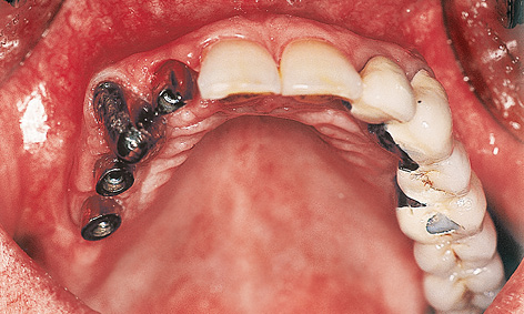
Fig 5-4f Cement-retained telescopic crown on tooth 13.
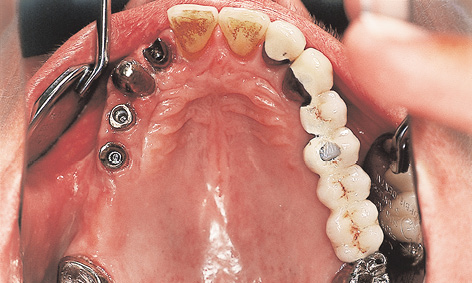
Fig 5-4g Customized abutments screwed onto the implants.
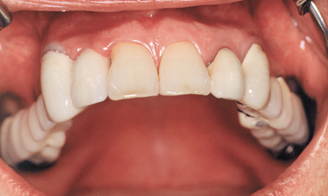
Fig 5-4h The fixed bridge has been provisionally cemented on.

Fig 5-4i Patient following treatment completion.
Exposure and prosthetic restoration
The patient was able to wear a provisional fixed bridge, supported on teeth 13 and 18, throughout the healing period. The mucosal situation in region 12 was optimized further by the incision used during implant exposure and by the suturing technique (the cosine curve technique, see Note on page 330). The same cosine curve technique was used for the exposure of implants 14 and 15. Copings were fitted both onto the implants in region 12, 14 and 15 and onto natural teeth 13 and 18 (Fig 5-4f). Custom-cast abutments were screwed onto the implants, while copings were cemented onto the natural teeth (Fig 5-4g). The telescopic fixed bridge was now provisionally secured onto all five abutments with TempBond Kerr; Fig 5-4h. The pale veneer was applied to the denture at the express request of the patient (Fig 5-4i).
Treatment course
- Implant placement (1997)
- 6 months to exposure
- 4 weeks to prosthetic loading
Treatment
|
Surgery: |
Dr Christoph T. Sliwowski |
|
Prosthetics: |
Dr Michael Weber |
|
Dental technology: |
Horst Mosch |
Cosine curve technique to improve the gingival situation
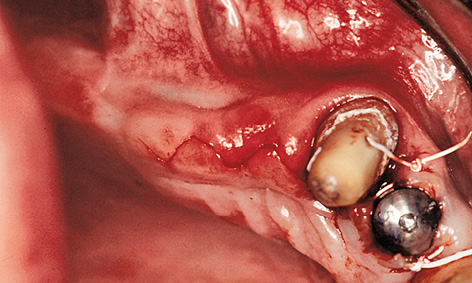
Fig 5-5a Incision shaped like a cosine curve.
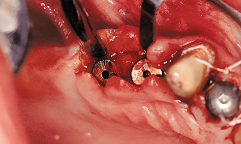
Fig 5-5b Mobilization of the buccal and palatal flaps.
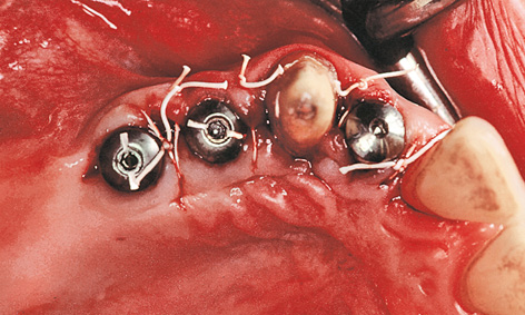
Fig 5-5c The peaks of the cosine curve have been adapted in the interdental spaces.
The subsequent gingival situation around the implants is determined primarily by the incision made at the time of exposure. Punching out the soft tissue over the implants must be avoided at all costs, as this would negate the optimal requirements for correction. One way of improving the gingival situation at the time of exposure is to use the cosine curve technique. In this technique, the incision is made centrally on the residual ridge and centrally over the implants, as well as slightly toward a palatal direction. The incision is shaped like a cosine curve (Fig 5-5a). Both the palatal and the buccal flap should then be mobilized slightly (Fig 5-5b). Once the cover screws are removed, healing abutments of the desired height and diameter are screwed on in their place. After this, the peaks of the cosine curve of each of the mobilized flaps are adapted in the interdental spaces – as in the lateral sliding flap technique – and stabilized with sutures (Fig 5-5c). This procedure is virtually atraumatic and makes optimal use of the available soft tissue. The sutures can be removed once the initial gingival stabilization has taken place (after approximately 7 to 10 days).
Atypical treatment course – problematic baseline situation
Restoration in a case of pronounced, one-sided residual ridge atrophy
Baseline situation
This male patient was to be fitted with a fixed prosthetic restoration of a large gap, which extended from wisdom tooth 18, across the middle and up to lateral incisor 22. The residual dentition in the maxilla was as follows: teeth 18 and 28 are free-standing, while teeth 22, 24 and 26 had been fitted with a fixed partial denture with a distal cantilever extension (Fig 5-6a). The patient was wearing a simple clasp prosthesis, which was very prone to fracture. Rehabilitation with a fixed restoration was planned. The shape of the residual ridge in the first quadrant was no longer ideal due to the prolonged toothlessness and the associated bone atrophy. The baseplate with optimal implant positions, as determined during the diagnostic procedure, clearly demonstrates this problem (Fig 5-6b).
Diagnostic tools
- Clinical examination
- Panoramic radiograph
- CT
- Dental cast analysis
- Surgical template and baseplate
Treatment plan
1.Implant placement and recording of the implant positions
2.Exposure and incorporation of the provisional restoration
3.Definitive prosthetic loading
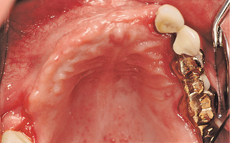
Fig 5-6a Atrophied residual ridge in the first quadrant.
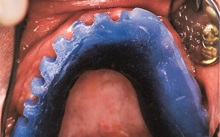
Fig 5-6b Discrepancy between the baseplate and the residual ridge.
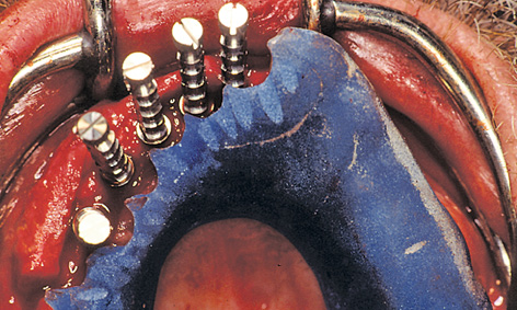
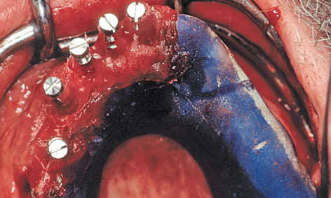
Fig 5-6d Impression copings, polymerized into the baseplate.
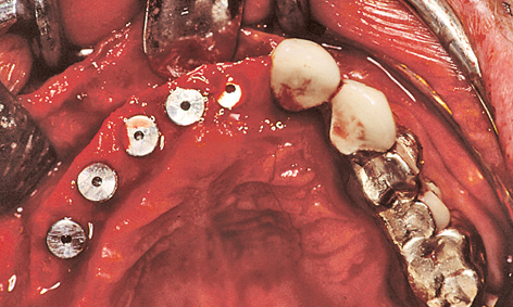
Fig 5-6e Inserted implants.
Implant placement and recording of the implant positions
It proved possible to insert the implants in positions 14, 13, 12, 11 and 21 into the existing local bone. As the buccal and labial atrophy of the residual ridge could not be fully reconstructed, at the request of the patient, the implants were placed further palatally than planned from the prosthetic point of view. To allow the superstructure to be prepared before exposure, it was necessary to record exact the exact positions of the implants and their relationships to one another and to the residual dentition.
For this purpose, impression copings were screwed onto the implants after the latter were inserted. The prepared baseplate was corrected accordingly, due to the greater than expected residual ridge atrophy (Fig 5-6c). The impression copings were integrated into the template with Pattern Resin (GC America)(Fig 5-6d). Once the baseplate was removed, cover screws were screwed onto the implants (Fig 5-6e). The mucoperiosteal flap was mobilized by periosteal slitting. This was followed by tight closure of the wound by suturing. The provisional restoration was prepared during the healing phase (see Note on the laboratory method on page 338).
Exposure with incorporation of the superstructure and gingival augmentation of the residual ridge
Very careful planning is needed for the exposure technique and the incision, especially in the anterior maxilla. The gum line over the future crowns is a key factor in the planning. The prosthesis teeth (without pink acrylic) show the buccal and labial course of the crowns (Fig 5-6f). In this case, all the implant penetration sites were located in the unattached mucosa of the buccal and labial vestibule. The exposure operation was used to gather more attached gingiva around the implants and to correct the mucosal situation.
On the palatal side of the implants, the incision extended only into the mucoepithelium. The epithelialized gingiva was dissected away from the connective tissue towards the palatal direction over a length of approximately 10 mm; this needs to be done without any perforations, if at all possible (split-flap technique). The periosteum was cut through at the end of the mucosal flap (approximately 10 mm palatally of the implants). The long flap extending toward the palatal direction had to be detached from the bone, working toward the labial and buccal vestibule (Fig 5-6g). Once the cover screws were removed, the prepared sterile inner crowns were screwed into place. The implant abutment lying furthest distally was screwed on first with the aid of the transfer (Fig 5-6h). The key could then be used to place the other abutments in any desired sequence. A method that has proved useful is to mark the components on the labial/buccal side so that they can be put into the correct order quickly during the procedure (Fig 5-6i). Once the screws were tightened, the provisional crowns were attached using a little TempBond with added Vaseline and the cement residues removed under visual control (Fig 5-6j).
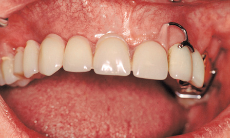
Fig 5-6f Unattached mucosa in the cervical region of the future crowns.
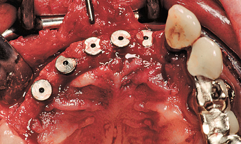
Fig 5-6g Split-flap technique.
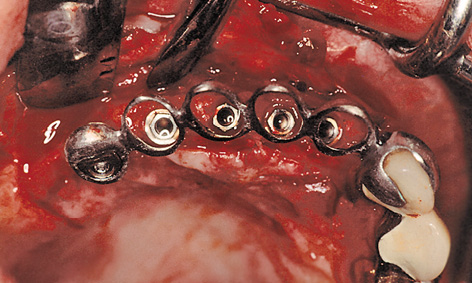
Fig 5-6h Fitting the abutments with the transfer key.
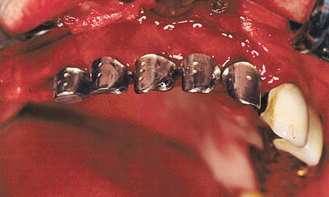
Fig 5-6i Markings on the abutments.
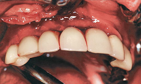
Fig 5-6j The long-term provisional implant bridge has been inserted.
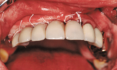
Fig 5-6k Stabilization of the pedunculated palatal flap.
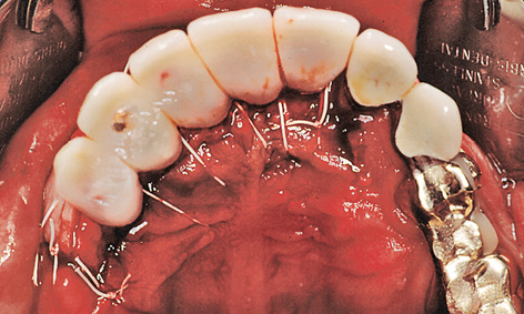
Fig 5-6l Adaptation of the thinned-out palatal flap.
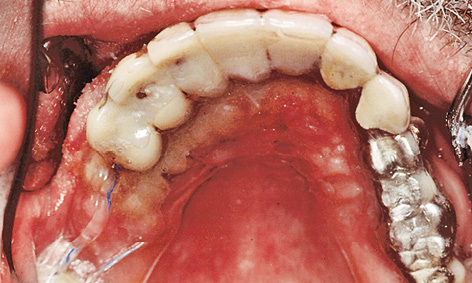
Fig 5-6m Dressing made of thermoplastic foil.
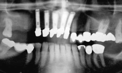
Fig 5-6n Postoperative panoramic radiograph.
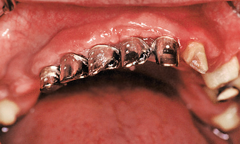
Fig 5-6o Clinical situation following the healing phase.
Attention: When tightening the retaining screws, it is essential to stop the abutments from twisting to the right on their own axes. Even the slightest twist causes tension, the result being that the transfer can only be removed with difficulty and that the superstructure no longer fits.
On the buccal/labial side, the roll flap was adapted to the implant abutments and secured with sutures (roll flap technique; Fig 5-6k). When suturing, the thinned palatal mucosal flap also had to be securely adapted to the bone (Fig 5-6l). Solcoseryl dental adhesive paste was applied and a prepared thermoplastic foil with a palatal cover put into place to allow the tissues to heal undisturbed (Fig 5-6m). The postoperative panoramic radiograph shows the exact fit of the abutments on the implants (Fig 5-6n). The healing phase was uncomplicated (Fig 5-6o).
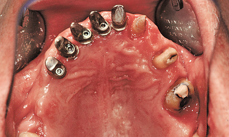
Fig 5-6p Repeat preparation of the teeth.
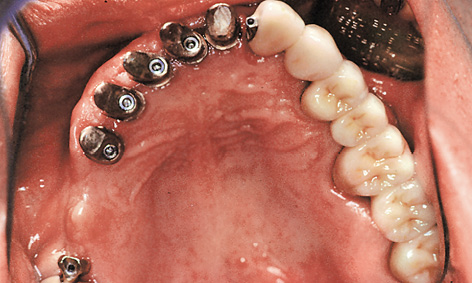
Fig 5-6q Cement-retained fixed dental bridge and crown 18.
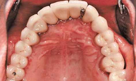
Fig 5-6r Securing the implant-supported section with mini-screws.
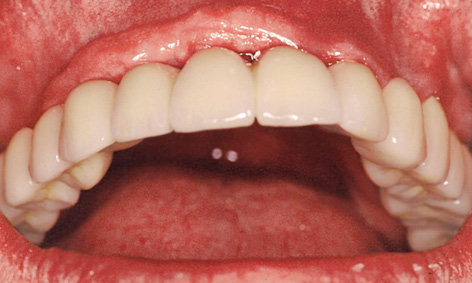
Fig 5-6s Overall rehabilitation.
Prosthetic restoration
More prosthetic steps followed once the situation had stabilized after about 6 to 8 weeks. For the overall rehabilitation, the bridge 22 to 27 was first removed (Fig 5-6p) and the abutment teeth prepared again. This was followed by impression taking. In the laboratory, the split structure was fabricated on the overall cast. The tooth-supported components that were to be cemented on were fitted with attachments for external screw retention. The implant-retained portion was to be cemented on provisionally and screwed onto the rest of the restoration.
The dental bridge 22-24-26-28 and crown 18 were inserted first and retained with Harvard cement (Harvard Dental; Fig 5-6q). After the provisional cement retention, the implant-supported part of the restoration was secured to the external attachments between 21 to 22 and 17 to 18 (Fig 5-6r). Some atrophy of the slightly overcontoured attached gingiva in regions 14 to 21 also had to be taken into account (Fig 5-6s).
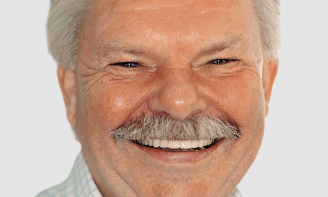
Fig 5-6t Patient following treatment completion.
The overall fixed maxillary rehabilitation from 18 to 28 was performed satisfactorily even without any bone augmentation (such as sinus floor elevation and posterior residual ridge augmentation). Figure 5-6t shows the patient after the treatment.
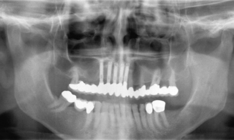
Fig 5-6u Follow-up panoramic radiograph taken after 14 years.
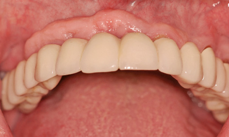
Fig 5-6v Clinical situation after 14 years.
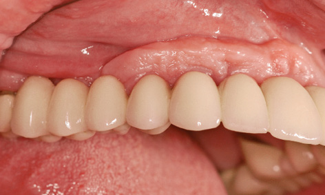
Fig 5-6w Excess attached gingiva over the implants.
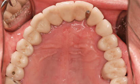
Fig 5-6x Virtually unchanged situation in the occlusal view.
Continued follow-up
The patient presented for a check-up 14 years after implant placement. A stable, virtually unchanged situation can be seen in the panoramic radiograph (Fig 5-6u). The fear expressed following incorporation of the restoration, namely that the roll flap on the buccal/labial side of the implants could degenerate, has not been realized even after many years (Fig 5-6v). The extent of the overcontoured attached gingiva, which has been preserved over the years, is particularly marked when compared to the course of the gingiva under the denture span in the molar region (Fig 5-6w). In the 14 years of use, there have been no complications, whether descent of the dental segment or damage to the screw-retained attachment (Fig 5-6x). The patient remains very satisfied with the outcome of the treatment and can laugh and smile freely at all times (Fig 5-6y).
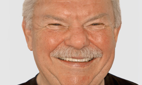
Fig 5-6y The patient can laugh freely with his securely fitting teeth.
Treatment course
- Implant placement (1997)
- 6 months to exposure
- 8 weeks to prosthetic loading
Treatment
|
Surgery: |
Dr Christoph T. Sliwowski |
|
Prosthetics: |
Dr Michael Weber |
|
Dental technology: |
Horst Mosch |
The cast coping laboratory method (relating to the case history on page 331)
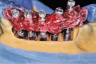
Fig 5-7a Placing the template onto the reamed-out cast.
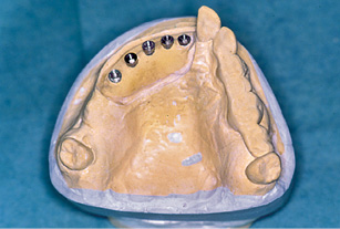
Fig 5-7b Embedded implant analogs.
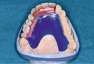
Fig 5-7c Wax-up.
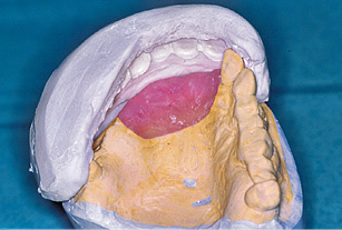
Fig 5-7d Preparing the matrix.
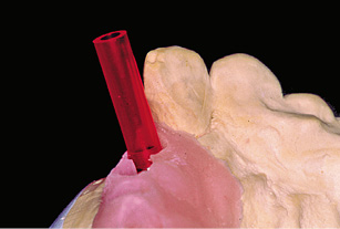
Fig 5-7e Plastic cylinders as supports.
Up-to-date casts are made up after exposure has taken place. After checking the impression copings for a tight fit in the template, the model implants are screwed into place. The cast is reamed out until the model implants are no longer in any contact with it and the template can once more be positioned precisely onto the cast (Fig 5-7a). The model implants are fixed into plaster, slightly below gum level.
After the template is unscrewed, the model implants remain in the cast, positioned analogously to the implants placed in the jaw (Fig 5-7b). A gingival mask is then fabricated. The cast is articulated and the prosthesis teeth set up. The positions of the prosthesis teeth on the cast (Fig 5-7c) are recorded with a plaster matrix (Fig 5-7d). The prosthesis teeth and palatal plate are removed, and the gingival mask perforated at the implant penetration sites.
The implant abutments are fabricated using the cast coping technique. The method is not new and is based on the University of California, Los Angeles (UCLA) abutment idea. In this technique, an individual abutment is modeled in wax on a burnout plastic cylinder, so that it can be cast in metal. Burnout acrylic cylinders/sleeves (Sub-Tec 2; BEGO) are selected as supports for the cast coping components and screwed onto the model implants (Fig 5-7e). These cylinders are ground to shape to fit the matrix.
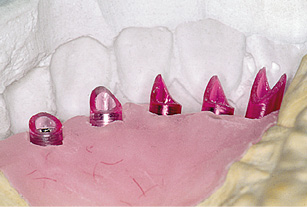
Fig 5-7f Shortened plastic cylinders.
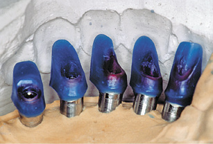
Fig 5-7g Modeled customized abutments.
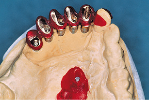
Fig 5-7h The modeled transfer.
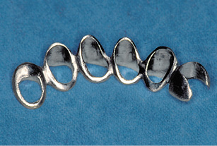
Fig 5-7i The cast metal transfer.
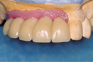
Fig 5-7j Provisional crowns on the customized abutments.
All the cylinders are adjusted in sequence (Fig 5-7f) and the custom abutments, which correspond to the inner crowns, are modeled in wax. The modeling is guided by the matrix (Fig 5-7g) and the gingival situation. Any discrepancies between implant position and crown can be compensated for by custom modeling. The modeled inner crowns are cast in metal and checked on the plaster cast.
To fix the definitive positions of the inner crowns relative to each other and to transfer them to the operation site, a transfer is modeled and cast in metal (Figsw 5-7h and 5-7i). Provisional crowns are then fabricated on the basis of the prosthesis teeth (Fig 5-7j).
Atypical treatment course – problematic baseline situation
Sinus floor elevation with vertical and horizontal augmentation and single-tooth implant with orthodontic treatment
Baseline situation
A 49-year-old woman required dental treatment in quadrants one to three, despite the good clinical appearance of her dentition (Fig 5-8a). Teeth 16, 22 and 28 needed to be extracted (Fig 5-8b). Tooth 22 had already received root canal treatment and developed an active fistula in the apical region (Fig 5-8c). The bone bed in the distal parts of the maxilla was not adequate for the stable, long-term anchoring of implants, so that bilateral sinus floor elevation needed to be performed first (Fig 5-8d).
Diagnostic tools
- Clinical examination
- Panoramic radiograph
- CBCT, SimPlant planning
- Dental cast analysis
Treatment plan
1.Extraction, bilateral sinus floor elevation with vertical and horizontal augmentation
2.Implant placement
3.Exposure and horizontal widening of the gingiva
4.Orthodontic mesialization of tooth 15
5.Definitive prosthetic loading
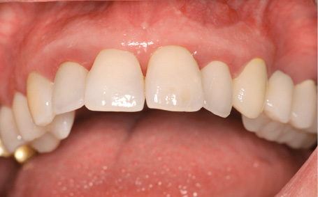
Fig 5-8a Clinical baseline situation.
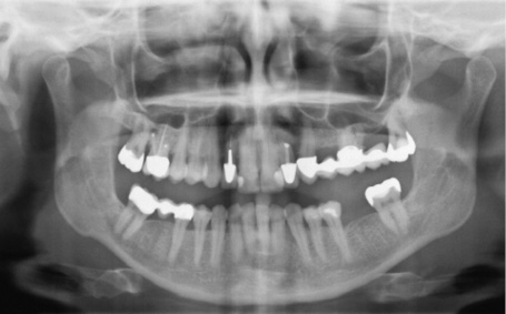
Fig 5-8b Panoramic radiograph before the treatment.
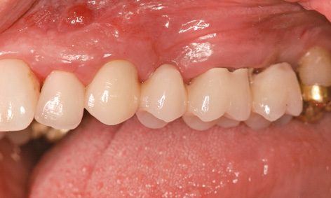
Fig 5-8c Fistula over tooth 22.
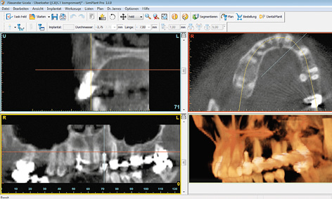
Fig 5-8d CBCT scan images before the sinus floor elevation.
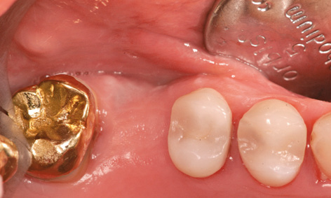
Fig 5-8e Gap left by the loss of tooth 16. The premolars are starting to migrate distally.
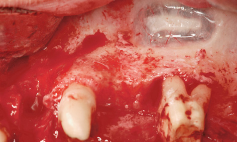
Fig 5-8f Fenestration over the root of tooth 26.
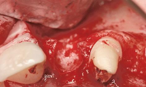
Fig 5-8g Extensive bone defect in region 22.
Sinus floor elevation and lateral augmentation
Working under general anesthesia, the procedure began with removal of the bridge on teeth 23, 26 and 28. This was followed by the extraction of teeth 22 and 28. Tooth 16 had already been extracted on a prior occasion, to ensure an intact mucosal layer for coverage after the sinus floor elevation (Fig 5-8e). An incision was made along the palatal surfaces of the teeth with a releasing incision distally of tooth 21. The access window to the maxillary sinus was created cranially of the root apices of tooth 26, without damaging them (Fig 5-8f). The prolonged inflammation around tooth 22 had led to an extensive bone defect, making implant placement impossible without prior augmentation (Fig 5-8g). Both sinus elevation and lateral augmentation were performed with Bio-Oss (particle size 1 to 2 mm) and the harvested bone chips. A large Bio-Gide membrane (Geistlich) (30 × 40 mm) was divided into smaller fragments for the two windows and for lateral augmentation in region 22. These membrane fragments were attached with titanium pins (Fig 5-8h). After the periosteal slitting, the flap was mobilized in such a way as to provide tension-free coverage of the whole operation area. It was attached with Gore-Tex and Mopylen 6-0 sutures (W. L. Gore and Resorba, respectively) using the simple interrupted and mattress stitch techniques (Fig 5-8i). An immediate provisional was fabricated out of Protemp (3M ESPE) over the stumps of teeth 23 and 26 with the aid of thermoplastic foiland incorporated (Fig 5-8j).
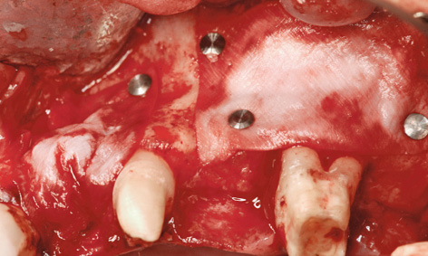
Fig 5-8h Augmentation.
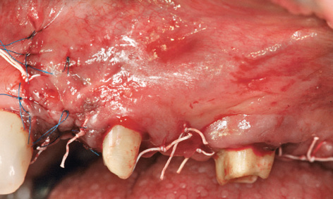
Fig 5-8i Tension-free wound suturing.
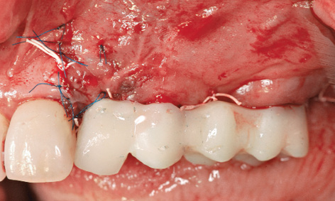
Fig 5-8j Short-term provisional restoration.
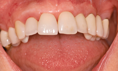
Fig 5-8k Stable healing course.
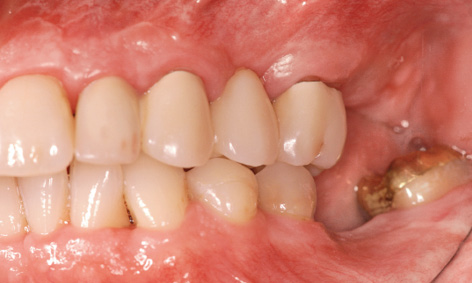
Fig 5-8l Long-term provisional
Implant placement
After the sutures were removed, the short-term provisional was exchanged for a metal-reinforced, long-term provisional (Fig 5-8k). This provisional replaced teeth 22 and 24, where the implants were to be inserted. Two additional implants were planned in region 27 and one in region 36 (Fig 5-8l). Implant placement took place 10 months after augmentation. The single implant in region 16 was inserted first (Fig 5-8m). Further migration of tooth 15 toward a distal direction is apparent in the occlusal view; this was to be corrected orthodontically (see Figs 5-8e and 5-8m).
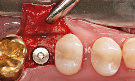
Fig 5-8m Inserted implant in region 16; distal migration of tooth 15.
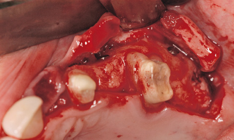
Fig 5-8n Creating the flap.
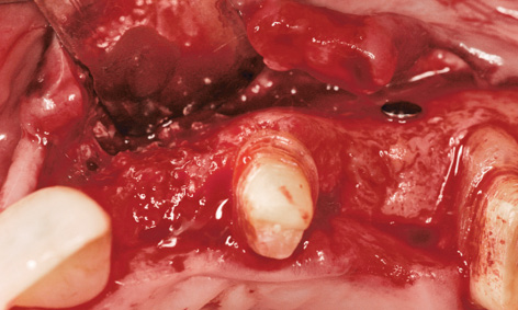
Fig 5-8o Result of the augmentation.
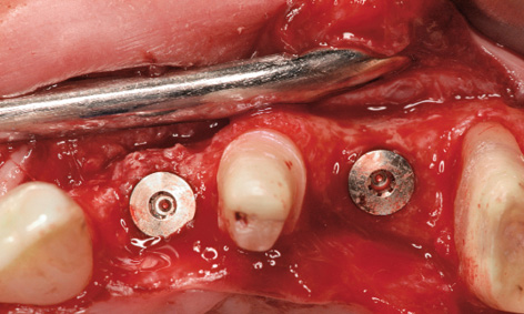
Fig 5-8p Bone spreading and insertion of implant 22.
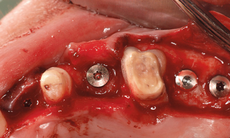
Fig 5-8q Insertion of further implants.
Fig 5-8r Concomitant insertion of implant 36.
On the left side, the incision was made along the palatal surface of the teeth. The releasing incision was made at the height of former tooth 28 (Fig 5-8n). Lateral augmentation in region 22 had also been very successful, and hardly any resorption of the augmentation material was apparent (Fig 5-8o). During preparation of implant bed 22, the bone bed was widened slightly by bone spreading and a 3.5-mm wide Neoss implant was inserted (Fig 5-8p). Further implants were inserted with primary stability in regions 24, 27 and 28 (Fig 5-8q). The single-tooth implant 11 mm in length and 4.5 mm in diameter was then inserted in the region of tooth 36 (Fig 5-8r).
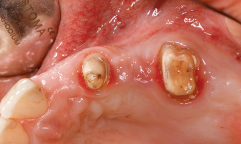
Fig 5-8s Clinical situation prior to exposure.
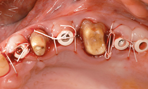
Fig 5-8t Exposed implants.
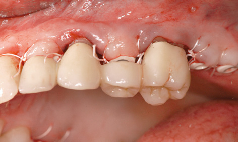
Fig 5-8u Modified long-term provisional.
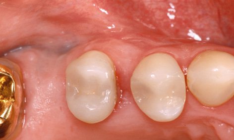
Fig 5-8v Distal migration of tooth 15.

Fig 5-8w Periodontal defect on the mesial side of tooth 15 and its treatment.
Exposure and orthodontic treatment
All the implants were exposed 1 year after insertion. The long-term provisional was still in use and was removed for the exposure (Fig 5-8s). The incision on the left side was shifted further palatally to widen the zone of keratinized gingiva. The cover screws were replaced with 5-mm high polyetheretherketone (PEEK) abutments and the flaps were adapted onto these (Fig 5-8t).
The long-term provisional needed to be adjusted to the new situation prior to incorporation (Fig 5-8u). On the right side, the gap between teeth 14 and 15 had grown because tooth 15 had migrated further distally. This condition needed to be corrected before the definitive restoration (Fig 5-8v). The large periodontal defect on the mesial surface of this tooth could have been a possible cause for the migration. In the exposure operation, the gingiva was reflected slightly more and this defect carefully cleansed by open curettage (Fig 5-8w). The surface of the root was mechanically cleaned and chemically decontaminated. The flap was fixed with Gore-Tex sutures without filling the defect (Fig 5-8x). The sutures were removed after 2 weeks (Fig 5-8y). After another 2 weeks, the healing abutment was replaced with a definitive titanium abutment, allowing the orthodontic straightening of tooth 15 to begin (Fig 5-8z). For the orthodontic treatment, a partial archwire on a ring was fitted around tooth 17, along with two brackets in regions 14 and 15. Abutment 16 was initially fitted with a provisional crown (Fig 5-8aa).
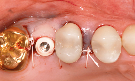
Fig 5-8x The wound has been sutured after the exposure.
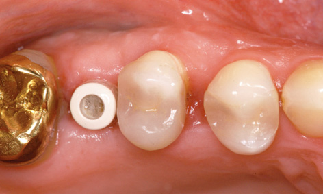
Fig 5-8y Healing on the right side.
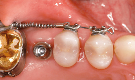
Fig 5-8z Start of the orthodontic treatment.
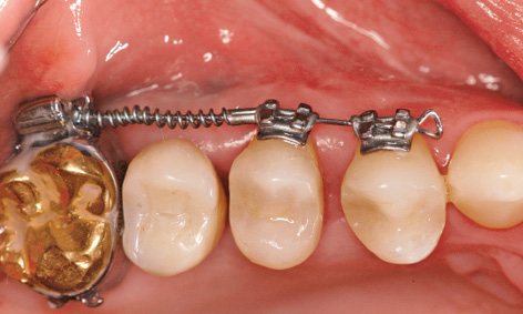
Fig 5-8aa Provisional crown on implant 16.
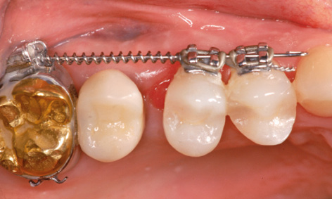
Fig 5-8bb The gap between teeth 14 and 15 has been closed by the orthodontic treatment.
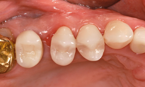
Fig 5-8cc The orthodontic apparatus has been removed.
Ten weeks later, the orthodontic straightening of tooth 15 was completed, allowing the definitive prosthetic restoration to start (Fig 5-8bb). The orthodontic apparatus was removed for this purpose (Fig 5-8cc) and an impression taken for definitive crown 16 (with the prefabricated framework). Until the incorporation of the crown on the following day (Fig 5-8dd), the position of tooth 15 was maintained with a simple spacer. An impression of the left side was taken 3 weeks after the exposure (Fig 5-8ee). Zirconia abutments were fabricated on implants 22 and 24, and titanium ones on implants 27 and 28 (Fig 5-8ff).
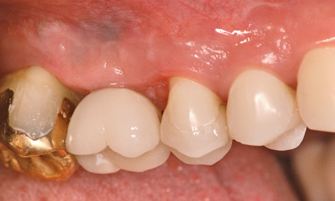
Fig 5-8dd Definitive crown on implant 16.
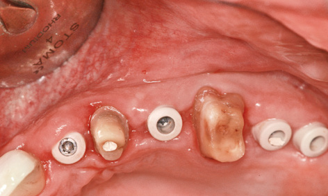
Fig 5-8ee The left side before impression taking.
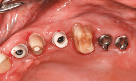
Fig 5-8ff Fitted abutments.
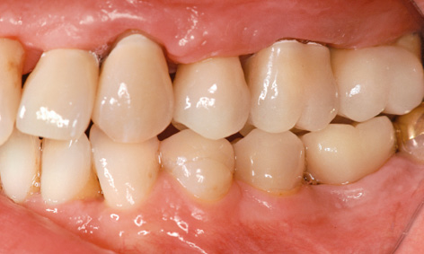
Fig 5-8gg Completion of the treatment.

Fig 5-8hh The patient can laugh again.
The ceramic individual crowns baked onto the zirconia caps were cemented on after the abutment screws were tightened. Crown 36 was also definitively inserted (Fig 5-8gg). After the 2-year treatment, the patient is very satisfied with the final result (Fig 5-8hh).
Treatment course
- Extractions and bilateral sinus floor elevation with posterior augmentation (2006)
- 10 months to implant placement
- 1 year to exposure
- 3 months’ orthodontic treatment before the definitive loading
Treatment
|
Surgery and prosthetics: |
Dr Christoph T. Sliwowski |
|
Orthodontic treatment: |
Dr Beata Sliwowska |
|
Dental technology: |
Dental technician Ludger Jansen, DentaLab |
Problems and complications
Sinus floor elevation with reconstruction of the residual ridge and gingiva
Baseline situation
This female patient had to have teeth 22, 23 and 25 extracted due to periodontal disease (Fig 5-9a). Teeth 23 and 25 had been used as abutments for a bridge. The severe periodontal loosening had resulted in extensive bone and soft tissue loss, creating unfavorable conditions for an implant-supported restoration (Fig 5-9b). In addition to the vertical and horizontal bone loss, the maxillary sinus extended far toward a mesial direction, so that too little bone was available in the premolar region to anchor implants in the long term. After the CT analysis, it was decided to perform sinus floor elevation (see page 383) plus vertical and horizontal residual ridge augmentation concomitantly with implant placement.
Diagnostic tools
- Clinical examination
- Panoramic radiograph
- CT, SimPlant planning
- Dental cast analysis
Treatment plan
1.Implant placement, left-sided sinus floor elevation with vertical and horizontal augmentation
2.Exposure and horizontal widening of the gingiva
3.Definitive prosthetic loading
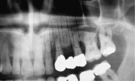
Fig 5-9a Panoramic radiograph before teeth were extracted.
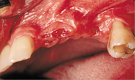
Fig 5-9b Residual ridge atrophy following the extraction of teeth 22, 23 and 25.
Implant placement and augmentation
After the palatal ridge incision and the dissection of a mucoperiosteal flap, a small window was cut into the apical premolar region of the maxillary sinus (Fig 5-9c). The maxillary sinus mucosa was detached and the implant beds prepared (Fig 5-9d). The gradual augmentation of the sinus floor with a mixture of Bio-Oss, autologous bone and autologous blood took place alongside the insertion of four implants (Fig 5-9e). The implants were placed so that they protruded approximately 2 to 3 mm above bone level, so that they would offer vertical support to the bone augmentation. The higher cover screw on the canine implant was to act as a zone of support for the membrane, preferably in the titanium-reinforced region. The large titanium-reinforced Gore-Tex TR9W membrane was adjusted and attached on the apical side. The prepared mixture of Bio-Oss and bone was then packed under it (Fig 5-9f).
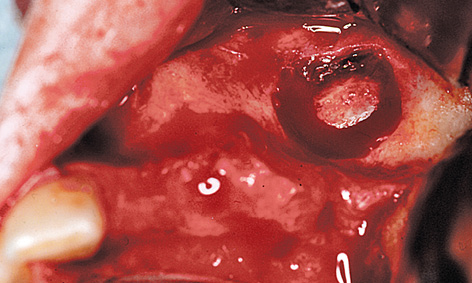
Fig 5-9c Fenestration of the maxillary sinus.
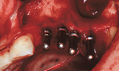
Fig 5-9d Preparation of the implant beds.
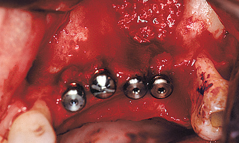
Fig 5-9e The cavity in the maxillary sinus has been filled and the implants inserted.
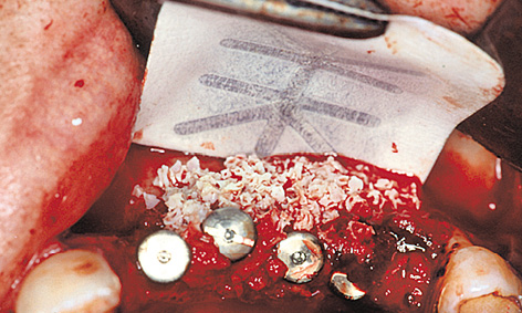
Fig 5-9f Membrane attached with pins on the apical side.
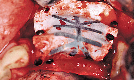
Fig 5-9g Adapted and stabilized membrane.
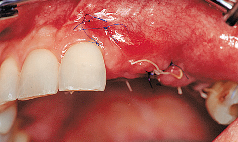
Fig 5-9h Mobilization of the buccal mucosa to cover the membrane.
Following shaping of the residual ridge, the membrane was adapted over the ridge to the palatal side and attached with titanium pins (Fig 5-9g). The flap needed to be repositioned by periosteal slitting without any tension and without exerting any pressure on the augmented area, before the wound was tightly closed with mattress and simple interrupted sutures (Fig 5-9h). The height of the implants above bone level is apparent on the panoramic radiograph, taken directly after the operation (Fig 5-9i). Since the vertical augmentation was undertaken with bone substitutes, a healing period of at least 9 months was required.
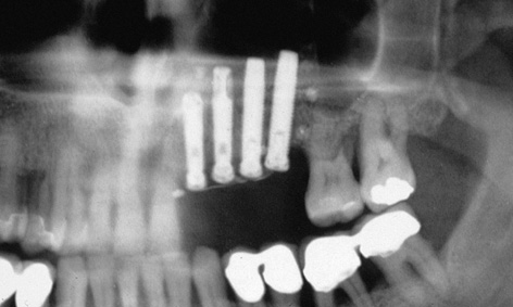
Fig 5-9i Panoramic radiograph after the procedure.
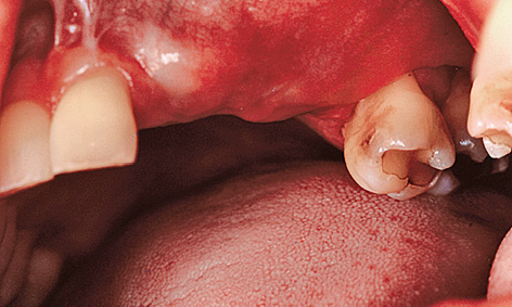
Fig 5-9j Unattached mucosa on the residual ridge.
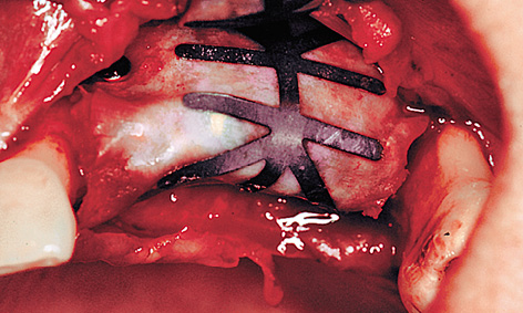
Fig 5-9k Exposure of the membrane.
Exposure and prosthetic restoration
As a result of the periosteal slitting and the displacement of the unattached mucosa in the coronal direction, there was no keratinized gingiva in the implant region (Fig 5-9j). For this zone to be reconstructed, connective tissue needed to be moved from the palate toward the vestibule. This was achieved with a combination of two methods: the split flap and the roll flap techniques (see pages 528 and 529). Following dissection of the flap, an access to the membrane and to the pins attaching it was created (Fig 5-9k). All the pins were taken out first to allow the membrane to be removed without tearing. To be on the safe side, the membrane was checked for intactness following removal.
The newly formed hard bone tissue had grown over all the cover screws apart from the supporting one, so that it had to be cut away to allow access to the implants (Fig 5-9l).
It had even been possible to reconstruct a bony support for the inter-implant papillae (Fig 5-9m). Healing abutments of reduced diameter were screwed onto the exposed implants to allow the mucosa to regenerate in the spaces between the implants (Fig 5-9n). The roll flap on the buccal/labial side needed to be tightly adapted to the abutments (Fig 5-9o).
The epithelial flap, which had been thinned out on the palatal side, was stabilized on the bone base with overlapping sutures (Fig 5-9p). The sutures were removed gradually over a period of 3 weeks (Fig 5-9q). The impression was taken after 5 to 6 weeks. Implant 22 was loaded with a CerAdapt (Nobel Biocare) abutment and an all-ceramic crown. Implants 23, 24 and 25 were loaded with the aid of the cast coping technique (Fig 5-9r). The follow-up radiograph (Fig 5-9s) shows good mineralization of the augmented bone compared to the baseline findings at the time of implant placement (see Fig 5-9i). Comparison of the intraoral images before and after the treatment makes it clear that not only the teeth, but also the residual ridge and the attached gingiva had been successfully restored (Figs 5-9t and 5-9u). The patient is very happy with this improvement (Fig 5-9v).
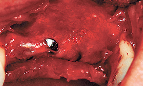
Fig 5-9l Regenerated bone under the membrane.
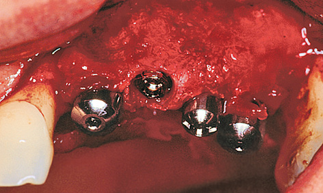
Fig 5-9m Bone support for the papillae.
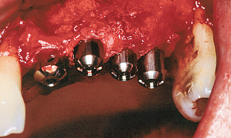
Fig 5-9n Healing abutments of reduced diameter.
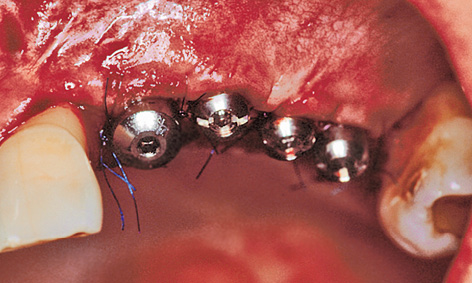
Fig 5-9o Palatal graft stabilized on the healing abutments.
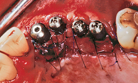
Fig 5-9p Adaptation of the thinned-out palatal flap.
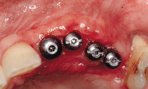
Fig 5-9q Clinical situation after 3 weeks.
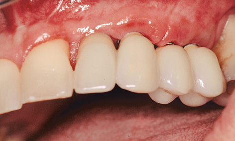
Fig 5-9r Prosthetic restoration.
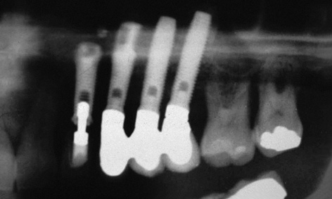
Fig 5-9s Check panoramic radiograph.
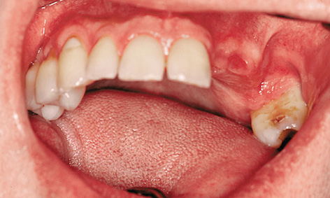
Fig 5-9t Maxilla before the procedure.
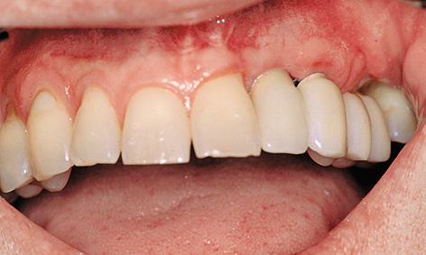
Fig 5-9u Fully reconstructed: residual ridge, attached gingiva and missing teeth.
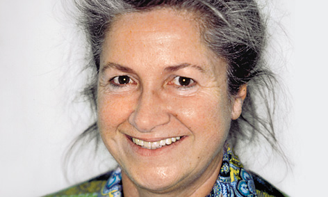
Fig 5-9v Patient following completion of the treatment.
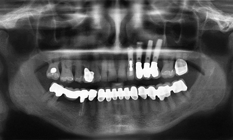
Fig 5-9w Follow-up panoramic radiograph after 13 years.
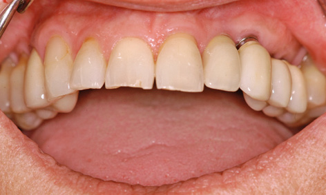
Fig 5-9x Overall view of the maxilla (cf. Fig 5-9t).
Continued follow-up
It is interesting to see how stable the treatment result remained after several years of functional use. The patient presented for a check-up after 13 years, and the clinical situation was documented at this point in time. The osseous situation appeared to be stable on the follow-up panoramic radiograph (Fig 5-9w). Implant 22, loaded with a ceramic individual crown, appears very natural in the overall view (Fig 5-9x).
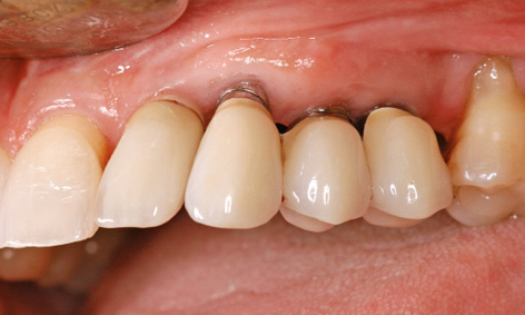
Fig 5-9y Visible metal on the distal implant superstructures. Healthy gingival situation after 13 years.

Fig 5-9z The patient’s long upper lip conceals the metal edges of the distal implants.
The implant positioned furthest toward the labial vestibule also shows the highest degree of recession and the highest overall proportion of metal in its superstructure (Fig 5-9y). However, the patient’s upper lip is long enough to allow her to smile broadly without revealing any metal parts (Fig 5-9z). The patient is not bothered by the visible metal edges and is more than satisfied with the final result.
Treatment course
- Implant placement, left-sided sinus floor elevation with vertical and horizontal augmentation (1999)
- 8 months to exposure and horizontal widening of the gingiva
- 6 weeks to the definitive prosthetic loading
- 8 months to exposure and horizontal widening of the gingiva
Treatment
|
Surgery: |
Dr Christoph T. Sliwowski |
|
Prosthetics: |
Dr Gregor Cwajgart |
|
Dental technology: |
Gerhard Makowski |
Problems and complications
Implant treatment after sinus floor elevation in two sessions
Baseline situation
This male patient’s maxilla exhibited a multi-tooth gap in the molar/premolar region on both sides (Fig 5-10a). A single-tooth gap was also present due to the loss of tooth 14 (still visible on the panoramic radiograph). Tooth 15, with grade II mobility, showed a loss of attachment of approx 70% (Fig 5-10b). The plan was to preserve the tooth for as long as possible despite its poor state and to extract it only once the superstructure was ready to be incorporated (Fig 5-10c). Both maxillary sinuses were so pronounced that they did not offer any secure anchoring potential for a simple implant placement. For this reason, bilateral sinus floor elevation was needed before any implants were placed (see page 383).
Diagnostic tools
- Clinical examination
- Panoramic radiograph
- CT, SimPlant planning
- Dental cast analysis
Treatment plan
1.Bilateral sinus floor elevation
2.Implant placement
3.Exposure
4.Definitive prosthetic loading
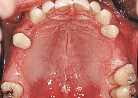
Fig 5-10a Baseline situation.
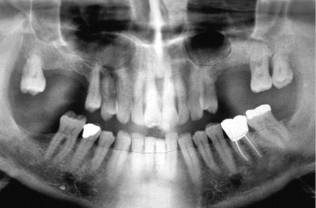
Fig 5-10b Panoramic radiograph.
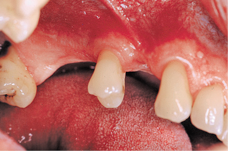
Fig 5-10c Gaps between the teeth in the first quadrant.
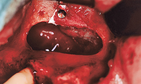
Fig 5-10d Sealing off the maxillary sinus mucosa with a membrane.
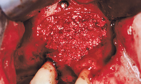
Fig 5-10e Lateral augmentation of the residual ridge.
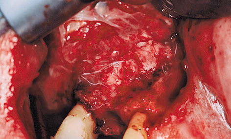
Fig 5-10f Atrisorb membrane.
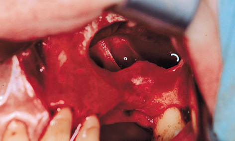
Fig 5-10g Bone septa in the left maxillary sinus.
< div class='tao-gold-member'>
Stay updated, free dental videos. Join our Telegram channel
VIDEdental - Online dental courses


