3D diagnosis and planning
Pronounced residual ridge atrophy
Radiologic and dental cast analyses are two key components of the preoperative diagnostic investigations. In the standard panoramic radiograph, the visualization of the anatomical structures in the anterior tooth region often lacks sharpness, so that it needs to be supplemented with a single-tooth radiograph. Far more reliable planning can be achieved with the aid of either conventional computed tomography (CT) or cone beam CT imaging (CBCT), also known as digital volume tomography (DVT). Both methods provide a metrically exact representation of the region, free of any superimpositions, thus allowing precise three-dimensional (3D) planning.
A CBCT image provides not only a pictorial overview of the situation, but also enables very detailed planning. The 3D reconstruction gives the best overview. In the case presented here, tooth 41 is sited far from the residual ridge and hangs loosely in the soft tissue (Fig 1-1a). The bone defect that has developed appears correspondingly extensive, and it may be assumed that augmentation will be necessary. The gap following the loss of tooth 31 has closed completely, so that only one incisor can be replaced, even though both the middle ones are missing. The distance between the roots of the neighboring teeth is relatively big, so that sufficient space is available in the mesiodistal direction (Fig 1-1a). For detailed planning, the data are input into a planning program, in this instance SimPlant (Dentsply). In the SimPlant program, the intended implant can be taken from a library (collection of all current implant types) and placed in the jaw. An abutment can also be selected after the positioning of the implant, and placed onto it. In this case, the program allows a Brånemark System implant (Nobel Biocare), 18-mm long and with a diameter of 3.75 mm, to be selected based on the available bone supply. The implant abutment (in this case, CeraOne (Nobel Biocare), height 5 mm) can be seen in all three dimensions and in the 3D reconstruction (Fig 1-1b). The distance between the implant and the neighboring teeth is best assessed on the consecutive panoramic sections (Fig 1-1c). The most important view when planning each individual implant is the cross-sectional view, which shows the width of the residual ridge (Fig 1-1d). It allows the transverse and vertical bone supply to be assessed accurately, providing a basis for the prognosis of the primary stability of the implant. Any bone deficits that are present can be identified and a need for augmentation already becomes apparent in the planning phase. The 3D reconstruction provides a good overview of the available bone supply and the positioning of the implant (Fig 1-1e). Better assessment of the position of the implant relative to the nerve (which needs to be marked manually; Fig 1-1f) is delivered by the semi-transparent view or full fade-out of the bone structures. The model, with the section going through the implant, may be rotated in any direction, giving a view of the planned implant position from all perspectives (Fig 1-1g). The bone densitometry function provides good guidance on the expected bone quality at the implant site (Fig 1-1h). However, because of the poorer quality of the detailed visualization compared to CT, this analysis is of limited use when applied to CBCT images.
For the treatment course, see page 13.
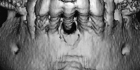
Fig 1-1a 3D reconstruction. Tooth 41 is now being retained only by the soft tissue.
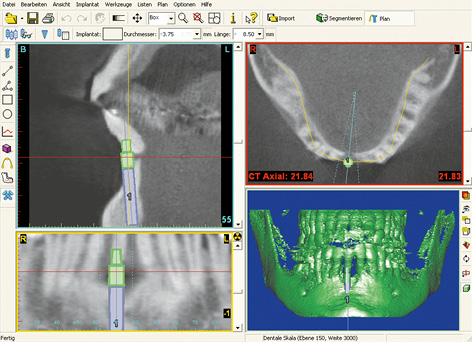
Fig 1-1b Implant planning with the SimPlant program: viewed in three aspects and 3D reconstruction.
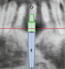
Fig 1-1c Panoramic section. Virtually inserted 3.75 × 18-mm Brånemark System implant with a 5-mm CeraOne abutment.
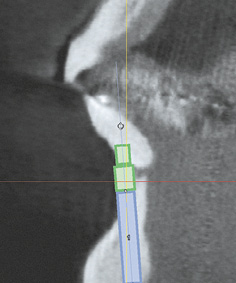
Fig 1-1d Cross-sectional view. Narrow residual ridge – labial bone deficit.
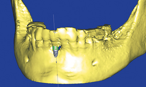
Fig 1-1e 3D reconstruction. Visualization of the position of the implant.
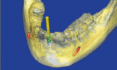
Fig 1-1f Semi-transparent 3D reconstruction with the nerves and longitudinal axis of the implant marked.
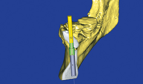
Fig 1-1g 3D visualization of the cross-sectional view.
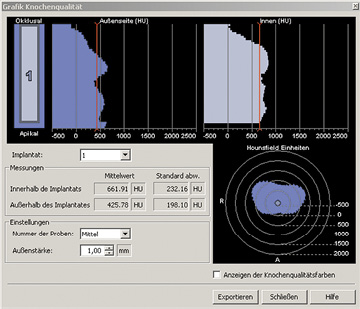
Fig 1-1h Bone densitometry around the planned implant.
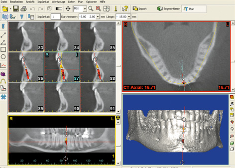
Fig 1-1j SimPlant planning.
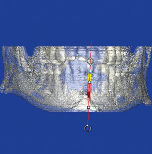
Fig 1-1k Semi-transparent 3D reconstruction with planned implant.
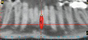
Fig 1-1l Panoramic section. Checking distance to neighboring teeth on the consecutive slices (from labial to lingual).
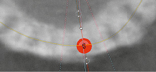
Fig 1-1m Axial section. Checking distance to neighboring teeth on the consecutive slices (from apical to coronal).
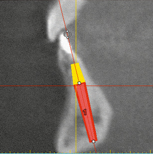
Fig 1-1n Cross section. Orientation of the implant taking account of anatomical and functional aspects.
Shortage of space, insufficient distance to the neighboring teeth
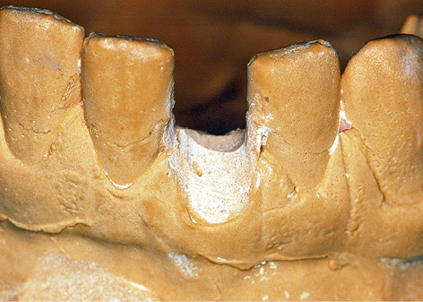
In this case, tooth 31 is not preservable due to painful internal resorption, and must therefore be extracted. This internal resorption has been confirmed on the CBCT images in all three planes. The width of the gap can be measured with high accuracy, not only radiologically, but also on the model after erasing tooth 31 (Fig 1-1i). The implant is planned using the SimPlant software (Fig 1-1j). One of the narrowest available implants, NobelDirect (Nobel Biocare), 16-mm long and with a diameter of 3 mm, has been selected due to the shortage of space. This implant is placed into the jaw virtually. The planning process is performed in all three planes and also with the aid of the 3D reconstruction. A visual representation of the positioned implant and its spatial relationship to the neighboring structures, particularly the teeth, becomes clearly apparent on the semi-transparent 3D reconstruction (Fig 1-1k). The panoramic section allows good assessment of the problem zones along the roots (Fig 1-1l).
It is advantageous to carry out an additional check of the spatial visualization on the horizontal (axial) section (Fig 1-1m). The most important evidence in most cases – the cross-sectional view – confirms that the dimensions of the residual ridge are adequate in this instance (Fig 1-1n).
For the treatment course, see page 16.
Single-tooth gap
The implant rehabilitation of a single-tooth gap in the anterior mandible, following the loss of one mandibular incisor, requires not only a special set of instruments, but also a particularly high level of precision from the implantologist. In most cases, the resultant gap is very narrow and the available space between the roots of the neighboring teeth extremely limited. Iatrogenic injury to the neighboring teeth can only be avoided with detailed preoperative radiologic investigations and by performing the surgical procedure with great care. If the residual ridge has healed, the freshly inserted implant can be loaded directly with a prosthesis, which is highly advantageous for both the patient and the dentist.
Because of the limited space, implants of reduced diameter, ie, narrow platform (NP) implants such as NobelActive (diameter 3.0 and 3.3 mm) and NobelDirect (diameter 3.0 mm) from Nobel Biocare, or Touareg (diameter 3.0 mm) from Adin or the K.S.I. Bauer screws, are particularly suitable for minimizing the risk of damage to the roots of neighboring teeth. Instruments required for implant placement include long shank drills, extra-long thread cutters and dental screwdrivers, as well as drill extensions, which can reach to the required depth in the narrow gap between the neighboring teeth (see page 16). Surgical guides or templates are used only in rare cases due to the limited space.
In the anterior tooth region, the single-tooth implant may be inserted directly after the tooth is extracted (immediate implant placement) or after the socket has fully healed (delayed implant placement). Requirements for immediate implant placement include: first, an adequate bone supply of good quality to anchor the implant with primary stability; and, second, the absence of any acute inflammation. After implant placement, the implant can be fitted with a cover screw and allowed to heal submerged, or with a healing abutment for transmucosal healing. In immediate implant placement, a healing abutment helps preserve the anatomical structures, such as the gingival margin and interdental papillae. Instead of a healing abutment, this function can also be performed by an interim crown on a provisional abutment, but these must be placed entirely out of both static and dynamic occlusion.
For the preoperative 3D investigations, see page 2.
Typical treatment course
Late implant placement with immediate loading
Baseline situation
Having lost teeth 31 and 43, this patient was fitted with a removable prosthesis that she had worn for many years, but that she found very uncomfortable and troublesome (Fig 1-2a). The patient wished to be rid of the prosthesis as soon as possible. Both gaps were very narrow and the jaw, particularly the region of tooth 43, had degenerated considerably (Fig 1-2b).
Diagnostic tools
- Clinical examination
- Dental cast analysis
- CBCT and SimPlant planning
Treatment plan
1.Implant placement, augmentation and immediate loading
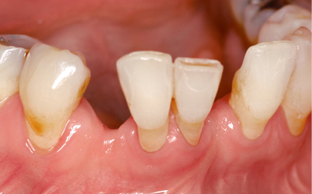
Fig 1-2a Missing teeth 31 and 43.
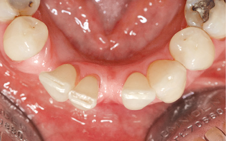
Fig 1-2b Horizontal atrophy.
3D analysis and SimPlant planning
A CBCT image was taken before implant placement and the implants were virtually positioned in the SimPlant program (Fig 1-2c). Because of the shortage of space and good bone quality, the plan was to use K.S.I. Bauer screws for both sites.
Attention: The advantage of K.S.I. Bauer screws is that they provide good primary stability and can be loaded immediately. They have been successfully used by the main author for many years as provisional implants for immediate loading. Despite earlier doubts, they are eminently suitable for use as definitive implants in extremely narrow gaps. They have a flexible section to allow the crown to be adjusted with regard to any prosthetic aspects.
Implant placement
Implant placement took place under general anesthesia and was performed in combination with the osteotomy of retained tooth 28 and bilateral sinus elevation. Before implant placement, the teeth located either side of the gaps were stripped slightly, to make more space for the crowns. The incision was made centrally over the residual ridge and extended further horizontally below papilla 41, 42 to provide a join. A labial flap was constructed, preserving the papilla, and both implants were inserted. The labial atrophy was treated with the harvested bone chips. Alignment of the implant heads was followed by tight closure of the incision with Gore-Tex (W. L. Gore and Associates) and Mopylen 6-0 sutures (Resorba) (Fig 1-2d). The first provisional crowns were manufactured and directly incorporated with the aid of theromoplastic foil. (Fig 1-2e).
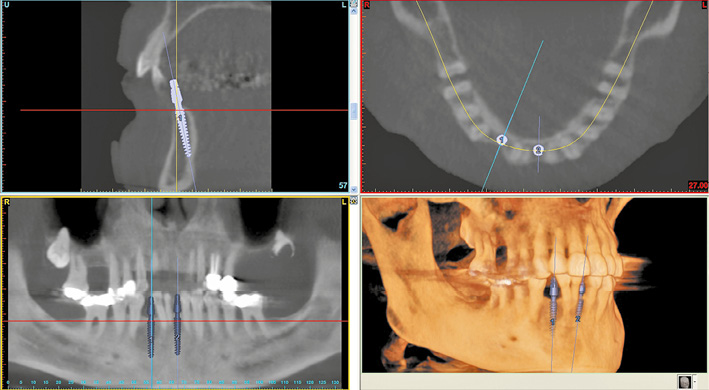
Fig 1-2c SimPlant planning of implants 31 and 43.
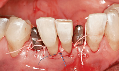
Fig 1-2d Inserted implants in the regions of teeth 31 and 43.
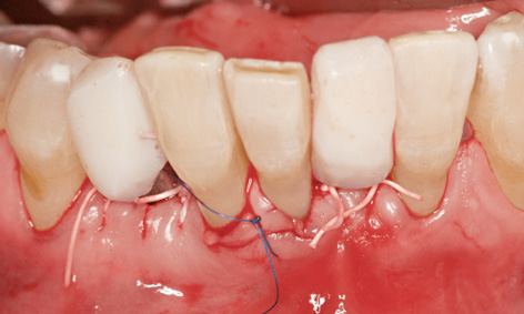
Fig 1-2e Provisional immediate crowns on the implants.
Prosthetic loading
One week later, the sutures were removed and the long-term crowns fabricated in the laboratory were incorporated (Fig 1-2f). The labial contour of the residual ridge looks considerably better even after simple augmentation (Fig 1-2g). Implant placement into the maxilla following sinus elevation was planned for 1 year later. The new CBCT image also provided a view of the peri-implant bone in the mandible in all three planes (Fig 1-2h). Comparison of the planned implant 31 (Fig 1-2i) with the implant already in situ (Fig 1-2j) in a cross-sectional view showed slight deviation of the apex of the positioned implant in the labial direction. This has resulted from the considerable resistance offered by the hard lingual cortical bone. The inclination of the implant head (Fig 1-2j) could be corrected by bending it. After 1 year, the bone and gingival situation around the implants continued to be stable. The patient was so happy with the appearance and function of the provisional crowns that she did not even want to have the definitive crowns fitted (Fig 1-2k).
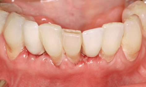
Fig 1-2f Incorporation of the long-term provisional crowns after 1 week.
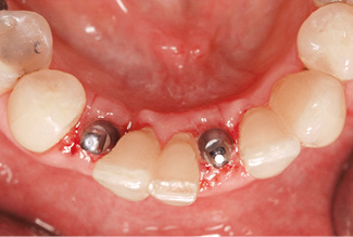
Fig 1-2g Residual ridge shaped by augmentation.
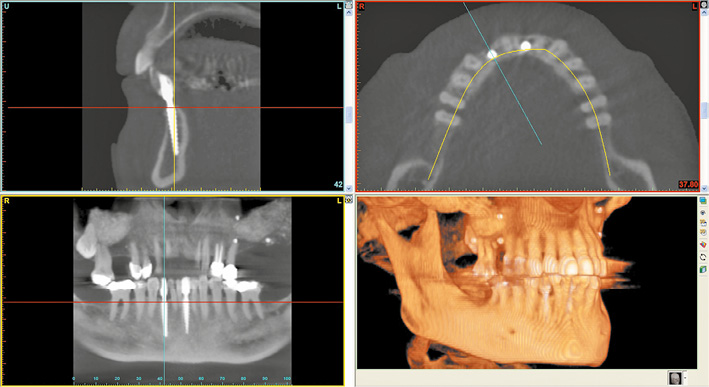
Fig 1-2h CBCT after 1 year and before the implant placement in the maxilla.
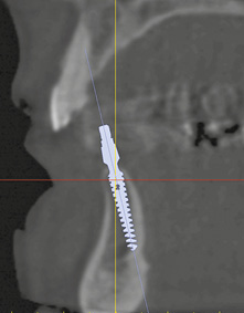
Fig 1-2i Planned position for implant 31.
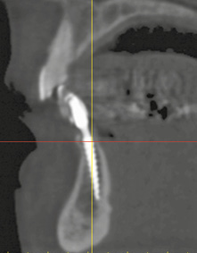
Fig 1-2j Cross-sectional view of implant 31 with a slightly bent head.
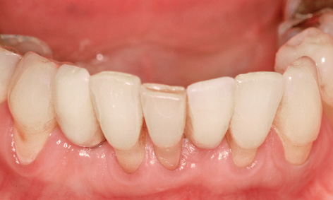
Fig 1-2k Provisional crowns (definitive at the patient’s request) after 1 year of functional use.
Treatment course
- Implant placement, augmentation and immediate loading (2010)
Treatment
|
Surgery and prosthetics: |
Dr Christoph T. Sliwowski, Dominika Sliwowska, DDS |
|
Dental technology: |
Dental technician Ludger Jansen, DentaLab |
Atypical treatment course – problematic baseline situation
Immediate implant placement following extraction
Baseline situation
Tooth 32, which shows little of note clinically but is very loose, can no longer be preserved due to a periodontal bone defect extending to its apex (Figs 1-3a and 1-3b).
Diagnostic tools
- Clinical examination
- Panoramic radiograph
- Single-tooth radiograph
- Dental cast analysis
Treatment plan
1.Extraction, immediate implant placement with augmentation
2.Secondary exposure
3.Cemented ceramic crown on a single-tooth implant
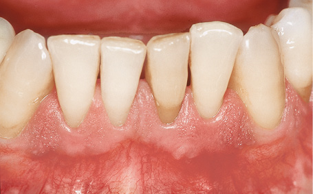
Fig 1-3a Tooth 32, no longer preservable.
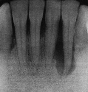
Fig 1-3b Periodontal bone defect extending to the apex.
Extraction and implant placement
Extraction of the tooth and creation of a mucoperiosteal flap exposed an extensive bone defect, which had also led to exposure of one root surface of tooth 31 (Fig 1-3c). A regular platform (RP) implant (diameter 3.75 mm), 21-mm long and with a conical neck, was inserted centrally into this defect and the underlying residual ridge (Fig 1-3d).
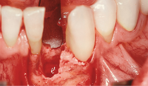
Fig 1-3c Exposed three-wall bone defect.
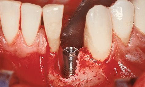
Fig 1-3d Inserted implant.
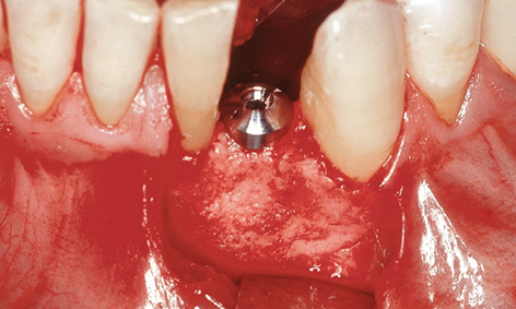
Fig 1-3e Augmentation with bone chips.
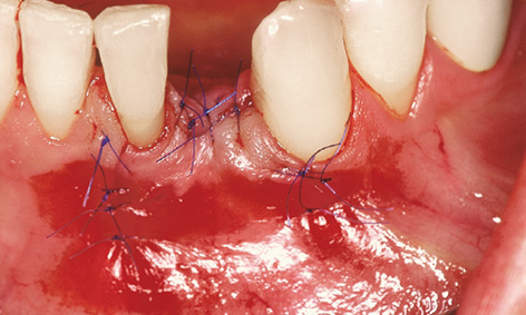
Fig 1-3f Wound closure with 6-0 sutures.
Instead of a cover screw, a 2-mm-high healing abutment was screwed onto the implant to act as a spacer. The remaining crevices in the bone defect were filled with the bone chips harvested during preparation of the implant bed (Fig 1-3e). Saliva-proof wound closure was performed following periosteal slitting and mobilization of a trapezoid flap, using monofilament, microsurgical 6-0 sutures (Fig 1-3f). Use of a membrane was not necessary for this three-wall bone defect.
Attention: Implants of reduced diameter (NP, approximately 3 mm) are best suited for replacing a lower incisor. Only narrow implants allow an adequate distance to be maintained from neighboring teeth. At the time (in 1998), the longest NP implant in the Brånemark System was 15 mm long; stable anchoring in the bone was doubtful at this length. The extraordinary implant length of 21 mm is an enormous advantage where a deep defect is present: it ensures stable anchoring in basal bone, which is so important in immediate implant placement, thus resulting in sufficient primary stability.
Exposure and prosthetic loading
After a 5-month healing period, the implant was exposed and the healing abutment exchanged for a higher one (Fig 1-3g). At this point, the panoramic radiograph showed stable anchoring of the implant in the bone, along with good regeneration of the former bone defect (Fig 1-3h). The implant was fitted with a CeraOne abutment and prosthetically loaded with an all-ceramic crown. In view of the very small distance between the implant and neighboring tooth 31 (one disadvantage of an RP implant) and the lack of bone before implant placement (Fig 1-3d), it was not possible to create an interdental papilla. However, this caused no impairment to the patient, even with his widest smile (Figs 1-3i and 1-3j).
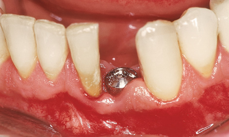
Fig 1-3g Displacement of the gum and interdental papilla 31 to 32.
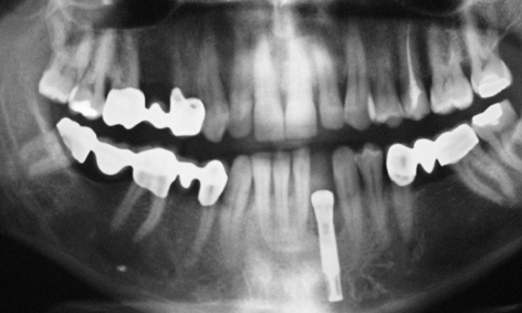
Fig 1-3h Panoramic radiograph prior to the prosthetic loading.
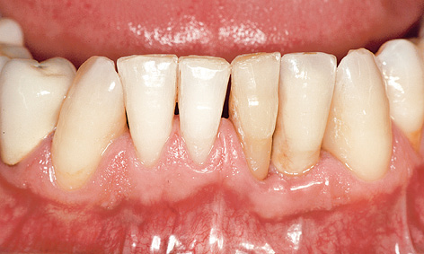
Fig 1-3i Clinical situation 4 years after the loading.
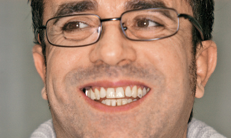
Fig 1-3j The patient 4 years after the loading.
Treatment course
- Implant placement (1998)
- 5 months to exposure
- 2 weeks to impression taking and fabrication
Treatment
|
Surgery: |
Dr Christoph T. Sliwowski |
|
Prosthetics: |
Dr Roland Althoff |
|
Dental technology: |
Ivonne Lewik |
Note
Narrow and high gap between neighboring teeth
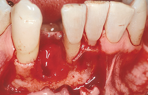
Fig 1-4a Exposure of the three-wall defect.
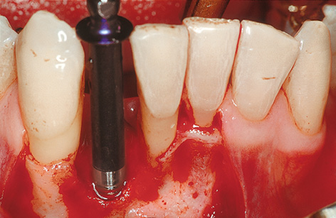
Fig 1-4b Insertion of the 3i Micro Mini implant with extra-long implant mount.
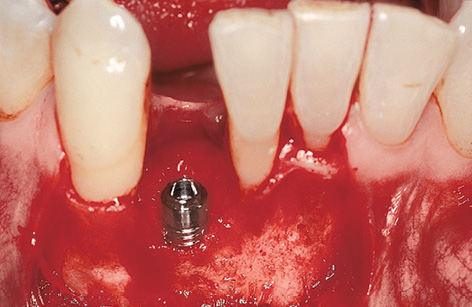
Fig 1-4c Inserted implant.
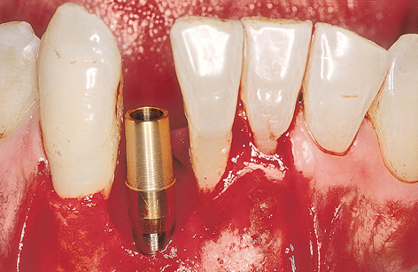
Fig 1-4d Provisional abutment.
The single-tooth gap following the loss of an incisor is very narrow at both crown and root (Fig 1-4a). This lack of space means that implants of reduced diameter should be inserted here, reducing the risk of injury to the neighboring teeth. Extra-long drills and thread cutters (possibly with an extension shaft) will need to be used when preparing the implant bed. An extra-long insertion driver or implant mount will also be necessary when placing the implant (Fig 1-4b).
The implant bed is prepared at the midpoint between the neighboring teeth, as an extension of the socket. Here, the gap is wide enough to insert a 3i Micro Mini (Biomet 3i) implant 3.25 mm in diameter with an extra-long implant mount (Fig 1-4b). Following insertion (Fig 1-4c), a cover screw or provisional abutment that will take the immediate crown is screwed onto the implant; this also requires the use of an extra-long screwdriver (Fig 1-4d).
Horizontal augmentation of a knife-edge residual ridge
This treatment course follows on from the 3D diagnostic investigations on page 2.
Baseline situation
This patient had only three mandibular incisors left following the closure of the gap left by tooth 31 (Fig 1-5a). Moreover, tooth 41 has suffered severe periodontal damage and is being retained only by an adhesive composite resin splint attached to the neighboring teeth (see Fig 1-5a). There is no attached gingiva whatsoever.
Diagnostic tools
- Clinical examination
- CBCT
- SimPlant planning
- Dental cast analysis
Treatment plan
1.Extraction, immediate implant placement, implant-supported single-tooth crown
2.All-ceramic crown on the CeraOne abutment
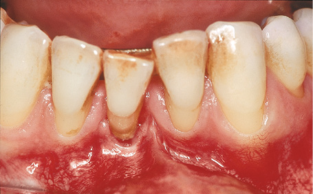
Fig 1-5a Tooth 41 is being retained only by a ligature splint.
Stay updated, free dental videos. Join our Telegram channel

VIDEdental - Online dental courses


