During syringe irrigation, a clinician applies tactile force to the syringe plunger. This force is transmitted to the irrigant into the syringe, where pressure is built up (Text Box
3.1). A clinician will need to apply different amounts of force and will feel different levels of difficulty to push the plunger when syringes of a different size are used, even if the actually developed pressure inside the syringe is identical; this results from the definition of pressure. Larger syringes are more difficult to depress and control. For the same reason, the clinician cannot draw reliable conclusions about the pressure.
While depressing the plunger, the pressure inside the syringe barrel remains considerably higher than the ambient pressure around the tip of the needle (which is nearly atmospheric). This pressure difference drives the irrigant through the needle and into the root canal, and that is why syringe irrigation is categorized as a
positive-pressure technique [
21]. The irrigant flow rate is proportional to this difference, but is also affected by the size of the needle and several other parameters (Text Box
3.1). So, for the same pressure difference, the flow rate through a smaller needle will be much less than through a larger needle. In other words, a larger pressure difference is required to achieve the same flow rate through a smaller needle.
A common mistake among clinicians which is also reproduced in several publications is that delivery of the irrigant at high flow rate is erroneously termed
forceful delivery or
delivery under pressure. Using a very large syringe combined with a fine-diameter needle would require a large tactile force, but the flow rate would still be low. In addition, it must be emphasized that the pressure of the irrigant delivered inside the root canal is always much lower than the pressure inside the syringe, because a significant pressure drop occurs along the needle. Thus, neither “force” nor “pressure” is an appropriate term to describe how fast the irrigant is delivered. Such information can only be provided by the flow rate [
8,
10], which can also be estimated clinically.
A 5-mL syringe has been recommended as a reasonable compromise between less-frequent refilling and ease of use. This syringe can be used to reach flow rates at least up to 0.20–0.25 mL/s even when combined with fine irrigation needles [
8]. Because of the very high pressures developed inside the syringe, a Luer Lock threaded fitting (Fig.
3.1) is always necessary to avoid accidental detachment of the needle during irrigation [
8].
Needles
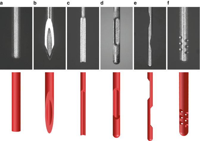
Over the years, several types of needles have been used to deliver irrigants into the root canals [
13,
37,
38,
50,
56,
66,
95,
112,
115]. These needles mainly differ in the presence of an open or closed tip and one or more outlets (Fig.
3.2).
Similarly to all other medical needles, the sizes of irrigation needles are most frequently described by the “gauge” system (Table
3.1) and seem to conform well to the relevant ISO specification [
9]. However, the “gauge” units cannot be directly compared to the size of instruments and obturation materials. The adoption of the millimeter as the standard metric unit to express needle size already recommended by the ISO for more than a decade [
52], and the development of a color code corresponding to that of the endodontic instruments could greatly assist clinical procedures [
9].
Table 3.1
Medical needle specifications according to ISO 9626:1991/Amd.1:2001 and corresponding size of endodontic instruments
|
21
|
0.80
|
0.800
|
0.830
|
0.490
|
80
|
|
23
|
0.60
|
0.600
|
0.673
|
0.317
|
60
|
|
25
|
0.50
|
0.500
|
0.530
|
0.232
|
50
|
|
27
|
0.40
|
0.400
|
0.420
|
0.184
|
40
|
|
28
|
0.36
|
0.349
|
0.370
|
0.133
|
40
|
|
29
|
0.33
|
0.324
|
0.351
|
0.133
|
35
|
|
30
|
0.30
|
0.298
|
0.320
|
0.133
|
30
|
|
31
|
0.25
|
0.254
|
0.267
|
0.114
|
25
|
In the past, large needles (21–25G) were commonly employed for irrigant delivery [
20,
24,
82,
87,
102]. Such needles could hardly penetrate beyond the coronal third of the root canal, even in wide root canals. More recently, the use of finer-diameter needles (28G, 30G or 31G) has been advocated, mainly because they can reach farther into the canal, even to working length (WL) [
6,
14,
19,
49,
69,
92,
117]. The effect of needle type and size on root canal irrigation will be discussed in more detail further on.
Physical Properties of Irrigants
Apart from the equipment (syringe and needle), the flow of irrigants is also affected by their physical properties, mainly density and viscosity (Text Box
3.2) [
67,
103,
113]. For commonly used endodontic irrigants, these properties are very similar to those of distilled water [
41,
105] because most irrigants are sparse aqueous solutions. The surface tension of endodontic irrigants (Text Box
3.2) and its decrease by wetting agents (surfactants) have also been studied extensively, under the assumption that they may have a significant effect on irrigant penetration in dentinal tubules and accessory root canals [
1,
36,
100] and on dissolution of pulp tissue [
97]. However, while density and viscosity affect the flow in all cases, the effect of surface tension is important only at the interface between two immiscible fluids [
58,
113]. Such an interface is formed between the irrigant and an air bubble, but not between the irrigant and the dentinal fluid, because these two liquids are miscible. Recent studies have confirmed that surfactants do not enhance the ability of NaOCl to dissolve pulp tissue [
25,
27,
55] or the ability of common chelators to remove calcium from dentin [
116] or to remove the smear layer [
26,
62]. In addition, bubble entrapment in the apical part of root canals is an unlikely event provided that certain guidelines are followed, as it will be discussed further on.
Irrigant Flow During Syringe Irrigation
Evaluating irrigant flow even in a simple straight and uniformly tapered root canal can be a very demanding task. It has been underlined that during irrigation, the root canal behaves mostly like a closed-ended system, so in
ex vivo and
in vitro experiments the apical foramen should be sealed [
10,
18,
47,
73,
101]. This seemingly minor detail has been overlooked in many experimental studies in the past, giving rise to doubt about the validity of their results, as pointed out by Tay et al. [
101]. In fact, a closed apical foramen results in a significantly more complicated flow pattern and adds considerable obstacles for irrigant penetration compared to a root canal open from both sides, even if no air bubbles are entrapped apically [
12,
109,
113].
Fluid flows are broadly categorized into
laminar and
turbulent ones (Text Box
3.3). In the case of root canal irrigation, turbulence would greatly assist irrigant penetration and refreshment due to the far more effective mixing [
34]. However, the development of turbulence inside root canals during syringe irrigation has not been verified experimentally yet. When the irrigant is delivered at very low flow rates (~0.01 mL/s) through a 30G needle, a steady laminar flow is developed within the root canal. At higher flow rates (up to at least 0.26 mL/s), the flow becomes unsteady, but it remains laminar [
10,
12,
109], contrary to previous reports [
56]. An unsteady flow changes smoothly over time, but it is not necessarily turbulent. It is likely that the formation of vortices (Text Box
3.4) and the unsteady flow during syringe irrigation could have been mistaken for turbulence in the past due to limitations of the visual assessment in real time. According to computer simulations, a higher, yet clinically unrealistic, flow rate (0.53–0.79 mL/s) may lead to the development of turbulence mostly close to the tip of the needle [
10]; however, these results have not been verified in experiments.
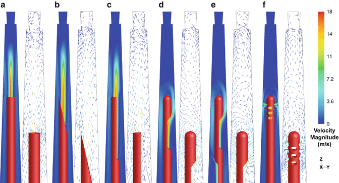
The type of the needle has also a substantial effect on the basic flow pattern developed in the root canal during syringe irrigation (Fig.
3.3), while other parameters such as needle insertion depth, root canal size, and taper have only a limited influence [
12–
16,
109]. Based on the needle design and the resulting flow, the available types of needles can be categorized into two main groups, namely, the
open–
ended and the
closed-ended [
13]. All needles create a jet (Text Box
3.4) at their outlet, but the exact position and shape of the outlet determines the orientation and, to some extent, the intensity of the jet.
In the case of the open-ended needles (flat, beveled, notched), the jet is very intense and extends along the root canal, apically to their tip (Fig.
3.3a–c). Within a certain distance, which depends on the geometry of the root canal, the insertion depth of the needle, and the flow rate, the jet appears to break up gradually. Reverse flow towards the canal orifice occurs near the canal wall. The jet formed by the flat and beveled needle is slightly more intense and extends further apically than that of the notched needle [
13,
109].
When closed-ended needles are used (side-vented, double-side-vented), the jet is formed near the apical side of the outlet (the one proximal to the tip for the double-side-vented needle), and it is directed apically with a slight divergence (Fig.
3.3d–e). The irrigant mainly follows a curved path around the tip and then towards the coronal orifice. A series of counterrotating vortices are formed apically to the tip, extending almost to the WL. Their size, position, and number may differ according to needle insertion depth, root canal shape, and flow rate. Despite the fact that irrigant can flow from one vortex to the next, the velocity decreases significantly towards the apex, so irrigant penetration becomes slower. The distal outlet of the double-side-vented needle has only a minor influence on the overall flow pattern because most of the irrigant (93.5 %) flows out through the proximal outlet; thus, it doesn’t provide any important advantage [
13,
109].
A special case of closed-ended needle is the multi-vented needle, suggested for root canal irrigation many years ago [
37,
38,
66]. Although this needle is not commercially available at the moment, it appears to develop a distinct flow pattern (Fig.
3.3f); several small jets are formed by the irrigant exiting the needle from the outlets proximal to the tip and they are directed perpendicularly to the canal wall. The most intense jets (73 % of the total flow) are formed through the pair of outlets most proximal to the tip. Most of the flowing irrigant is directed towards the canal orifice, while very low velocities are noted apically to the tip [
13].