(5.1a)
(5.1b)
Under a physiological medium with pH ∼7.2, like blood plasma, therefore, both H2PO4 − and HPO4 2− are not only the stable and predominant species but also present in a very similar content. The PO4 3− content is marginal if the dissociation equilibrium should apply. Hydroxyapatite and its derivatives are precipitated via nucleation and crystal growth processes. Permitting orthophosphate ions of a form HnPO4 3− (n: 0–2) to take part in the formation of stoichiometric HAp, Eq. 5.2 describes the overall precipitation reaction:

(5.2)
When two HPO4 2− ions replace two PO4 3− ions at the b-sites (XO4), one vacant Ca site is created due to the charge compensation principle. Unfortunately, powder X-ray diffractometry cannot discern such substitution, but 31P nuclear magnetic resonance (NMR) spectroscopy could distinguish PO4 from HPO4 owing to their different chemical shift values. The substitution of carbonate ions at either a- or b-site introduces further complexity. The atomic ratio Ca/P is a measure of the nonstoichiometry: it frequently happens that precipitated calcium phosphate crystallites give a set of X-ray diffraction lines assignable to HAp, but the ratio Ca/P is far below 1.67, even below the ratio (1.5) for TCP [2]. Appropriate imperfection should stabilize the lattice owing to entropy effects and hence reduces the solubility product Ksp. That is, when the imperfection is exceedingly high to cause strains in the lattice, the lattice will be destabilized and the crystallite size decreases to store the excess energy in a form of surface energy. Such smaller size and large specific surface area favor to stimulate dissolution of the calcium phosphates or the reverse reaction of Eq. 5.2. Dissolubility depends on the lattice energy itself and the energy of hydration: the net free energy ∆G = ∆Hhyd (the sum of the heat of hydration) + U (lattice energy). Since the calcium orthophosphate family members, such as dicalcium phosphate (CaHPO4; anhydrous form: DCPA, dihydrate: DCPD), octacalcium phosphate (Ca8H2(PO4)6•5H2O: OCP), tricalcium phosphate (Ca3(PO4); α- and β-TCP), and HAp, consist of the same ions, i.e., Ca2+ and PO4 3− or HPO4 2−, dissolubility is mostly a function of the lattice energy, while the energy of hydration of the component ions primarily depends on the pH of the medium. The solubility phase diagram given by Chow [3, 4] shows that HAp is least soluble among those members in the whole pH range 4.4–13, in accordance with the smallest value of Ksp (−log Ksp = 116.8), followed by α-TCP (−log Ksp = 28.9).
Our blood plasma is supersaturated in calcium and orthophosphate ions with respect to apatite precipitation. In other words, our blood contains calcium and phosphate ions more than enough in concentration for apatite crystallization. Then, may a question arise why not apatite should be precipitated in blood in our ordinary life. At this moment, no clear explanation is provided: one can say that our blood vessels or their endothelial tissues would not allow heterogeneous nucleation. The nucleation process of this kind is thermodynamically much advantageous than its counterpart process: homogeneous nucleation. Consider diamond dust (homogeneous nucleation of water) will require a temperature range far below the freezing temperature, say −10 °C or at much lower temperature in highly clean atmosphere, but frosting (heterogeneous process), on the other hand, is observed when temperature is just below 0 °C. In either case above, thermodynamic significance is the activity of the relevant species, but not their concentration. The incredibly small value of the solubility product Ksp, aforementioned, indicates that free calcium and phosphate ions can never coexist under the physiological pH. Then, one may interpret the apparent stability of blood plasma with respect to the apatite precipitation as showing that the activity of those ions is kept below the level for crystallization for some reasons: chelation with blood proteins or other molecules is possible to depress the activity. Yet, any trigger, like sudden change in pH from defective homeostasis, puts such latent potential into action. Probably, that applies to spontaneous apatite deposition on a few kinds of materials to be described below.
5.1.2 Materials Inducing Apatite Deposition Under Physiological Conditions
5.1.2.1 Bioactive Materials
Materials are classified into many groups in terms of specific properties. For biomedical applications, physicochemical reactions such as apatite deposition, biodegradation or in vivo resorption, or protein adsorption at the material surface under the body environment are of vital importance as well as biological material–cell interactions. Apatite layer deposition is one of the most crucial reactions of bone substitutes, partly because it assures them to form direct bonds to bone tissues. They are sometimes denoted as being bioactive. Table 5.1 gives examples of bioactive, inert, and resorbable materials. The materials classified as bioactive will spontaneously deposit apatite on their surface when in contact with blood plasma or implanted in bone tissues. Note here that the term “bioactive” is also used in a very different meaning to represent literary “biologically active,” e.g., to stimulate tissue regeneration, and hence, one should pay good attention on what the work really means.
Table 5.1
Some examples of ceramic biomaterials classified by interactions with living tissues
|
Interactions
|
Components, products
|
Applications
|
|
|---|---|---|---|
|
Bioinert
|
Oxides
|
Al2O3, ZrO2, ZrO2-toughened Al2O3
|
Hip-bone cup, head
|
|
Glass-ceramics/leucite, Li2Si2O5, F–(Na, K)2O– CaO–SiO2
|
Tooth crown, staining, layering
|
||
|
F–Na2O–Al2O3–SiO2
|
Filler: glass ionomer cement
|
||
|
Nonoxides
|
Colloidal SiO2, ZrO2
|
Filler: tooth cement
|
|
|
Pyrolytic carbon
|
Heart valves
|
||
|
Bioactive (Non-resorbable)
|
Silicate glasses
|
Bioglass® and those with similar compositions
|
Ear ossicles, coatings
|
|
Borosilicate glasses
|
13-93B1, 13-93B2
|
Bone regeneration scaffolds
|
|
|
Silicate glass-ceramics
|
Ceravital®
|
Bone substitutes, defect filler
|
|
|
BIOVERIT®
|
Bone substitutes
|
||
|
A-W GC®
|
Bone substitutes
|
||
|
Sol-gel glasses
|
Ca silicates
|
Gene stimulating
|
|
|
Oxide gels
|
Mesoporous SiO2 gel (Nakanishi’s recipe)
|
Vehicle: gene, proteins
|
|
|
Amino-modified SiO2 gel particles Bone graft, filler
|
Bone graft, filler
|
||
|
TiO2 gel layers Ti surface modification
|
Ti surface modification
|
||
|
Calcium phosphate
|
Ca5(PO4)3(OH)
|
Bone defect and tooth cavity filler
|
|
|
Degradable, resorbable
|
Borate glass
|
13–93 cotton candy
|
Wound healing
|
|
Calcium phosphate
|
Ca5(PO4)3(OH)
|
Bone defect and tooth cavity filler
|
|
|
Ca3(PO4)2
|
Filler: tooth cement
|
The invention of Bioglass® and its family by Hench [5, 6] in the last days of the 1960s was epoch making: they were the first man-made bioactive materials that form a strong bond to living bone tissue. They are silicate glasses in a specific composition region A in Fig. 5.1 in the system Na2O–CaO–SiO2 with a small portion of P2O5. Discussions on the mechanism of bone material bonding have been originated from the analysis of the interactions between Bioglass® and bone tissues. Therefore, it is appropriate to describe some details about Bioglass® family. The glasses in the region circled with a broken line inside of region A are so active as to form bonding with soft tissues like the eardrum membrane. A glass with an asterisk (⋆) in the center of region A which has a code name 45S5 consists of 45SiO2, 24.5CaO, 24.5Na2O, and 6P2O5 (in mass %) and exhibits the highest biological activity. It is frequently denoted as Bioglass without any notice. A layer of carbonated apatite (hydroxy-carbonate apatite, HCA), as well as a silica-rich layer, was found at the interface of a 45S5 implant and the bone tissue in which the glass implant was embedded [5, 6]. Other glasses, glass-ceramics, or oxide gels listed in Table 5.1 that are classified as bioactive deposit similar HCA layers on their surface when implanted in bone tissues. Several review papers have been published.
Fig. 5.1
The composition region (mass%) of Bioglass® family in the system Na2O–CaO–SiO2 that includes 6 mass% P2O5 (Modified and redrawn based on Ref. [3]). The filled circle, CaSiO3. A, the region of Bioglass®. The glasses inside the broken line bond to soft tissues. The asterisk, 45S5 (45SiO2–24.5CaO–24.5Na2O–6.0P2O5 (mass%)). B, the region of inert glasses, like window glasses, for which no surface hydrolysis takes place under ordinary conditions. C, the region of water-soluble glasses. D, the region of no glass formation
To name a few, Hench et al. [7] presented several examples of ceramic materials in clinical practices, including tooth crown application of inert glass-ceramics. Cormack and Tilocca stressed the importance of analyzing the correlation between the structure and biological activity of those active glasses and glass-ceramics [8]. In contrast, Hoppe et al. summarized dissolution of those ceramic materials from more biological viewpoints, i.e., biological response of our living cells to the ionic entities dissolved from those active glasses and ceramics [9]. Jones has brought up some problems that Bioglass® and bioceramics have to overcome, by proposing new materials like bioactive nanoparticles and organic–inorganic hybrids [10].
5.1.2.2 Zeroth Order Mechanism of In Vivo Apatite Layer Deposition on Classic Silicate Systems
A sequence of reactions proceed one after another at the interface and lead to the formation of apatite layers, as is widely accepted nowadays: (a) the surface of glass or glass-ceramics is hydrolyzed to release calcium ions, (b) leaving a silica-rich layer on the surface (Eq. 5.3a):


(5.3a)
(5.3b)
The hydration of Si–O–Na+ releases more OH together with Na+ ions (Eq. 5.3b). (c) The hydrated silica-rich layer serves the sites of heterogeneous nucleation of apatite. This layer may be protective of the glass surface from further corrosion under high pH ∼9 which is attained by the hydroxyl ions due to the hydration processes (Eqs. 5.3a and 5.3b). The local high pH also drives the apatite formation (Eq. 5.2). Thus, the calcium ions released from Bioglass® as well as hydroxyl ions contribute greatly to further increasing supersaturation or (d) trigger the nucleation. Clark et al. [11] employed Auger electron spectroscopy to analyze the surface reactions in the earlier stages, while Hayakawa et al. used 29Si magic angle spinning (MAS) NMR technique [12, 13] to confirm that recondensation of those resulted Si–OH back to Si–O–Si also takes place in the silica-rich layer. This reverse reaction would rationalize the protective activity of the layer.
Several years after the introduction of Bioglass®, another glass-ceramic bone substitute family Ceravital® was introduced in 1973 by Brömer, Pfeil, and Käs [14]. Gross and his co-workers refined the composition to improve mechanical strength [15]. A typical member in the Ceravital® family contains smaller fractions of Al2O3 and Ta2O5, in addition to 38SiO2, 13.5Ca3(PO4)2, 31CaO, and 4Na2O as the primary components, while it contains 1 % TiO2 (in mass %) as the crystallization initiator. It is capable of depositing an apatite layer at the material–bone interface. A decade later, another bone-bonding glass-ceramics, BIOVERIT® family [16, 17] and Cerabone A-W® (A-W GC®), were commercialized from Jena and Kyoto, respectively. A member of the BIOVERIT® family, BIOVERIT® II, is derived from an aluminosilicate mother glass with an approximate composition of 45SiO2, 30Al2O3, 12MgO, 9(Na + K)2O, and 4F (in mass%). This mother glass experiences phase separation into two glass phases on heating, followed by crystallization to yield glass-ceramic that involves a mica phase (fluorophlogopite), which has a spherically arranged lamellae (cabbage-like) microstructure with cordierite precipitated between the mica platelets. Owing to this mica precipitation, the glass-ceramics is machinable with ordinary metal tools, enabling on-site modification during surgical procedure. It is common that the presence of Al or other oxides, known as intermediate oxides in glass science, suppresses apatite-depositing ability of glass, primarily because those metal oxides highly suppress the hydrolysis of the glass surface. The Al species is present in the cordierite phase and AlPO4 in BIOVERIT® II and III, respectively. For this reason, the glass-ceramics are active to deposit apatite when implanted.
It was almost the same time that Kokubo, Yamamuro, and their group members fabricated Cerabone A-W® or A-W GC® [2, 18, 19] from a glass of the composition 46MgO–45CaO–34SiO2–16P2O5–1CaF2 (mass%). Since surface crystallization, or heterogeneous nucleation and crystal growth, takes place in the mother glass, pulverization, heating, and sintering processes are inevitable to secure mechanical strength appropriate for load-bearing bone substitutes, like those for vertebra and iliac bones. Apatite and β-wallastonite (β-CaSiO3) are the precipitated phases in the mass fractions ∼38 % and 34 %, respectively, dispersed in the glass matrix of an approximate composition 17MgO–24CaO–59SiO2 (mass%). The name A-W is after those phases. Figure 5.2 demonstrates the presence of an apatite layer at the interface between A-W GC® and the tibia of a rat after implantation for 8 days [19]. A similar apatite layer was observed on pieces of A-W GC® in an in vitro experiment [2] where the samples were soaked in a simulated body fluid (SBF) [5, 6].
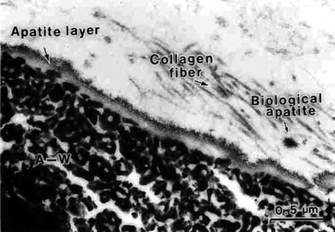
Fig. 5.2
A scanning electron micrograph of the interface between A-W GC® and a bone tissue (rat tibiae), indicating a newly deposited apatite layer (8 days after implant) (Reproduced from Ref. [19] by permission of John Wiley & Sons Ltd.)
5.1.3 Bioactivity as a Tool for Apatite Layer Coating Under In Vitro Conditions
5.1.3.1 Apatite Coating on Materials Provided with a Bioactive Surface
SBF or Kokubo’s solution is an aqueous solution that contains the same inorganic ions as blood plasma in similar concentrations, whose recipe has been chosen as a result of extensive trials [5, 6]. Table 5.2 lists the concentrations of selected ions in blood plasma (HBP) and SBF (std-SBF). The in vitro (in SBF) deposition of a new apatite layer similar to that deposited in vivo is a strong piece of evidence that SBF well reproduces the in vivo apatite deposition under in vitro conditions [5, 20–22]. The recent worldwide round robin test confirmed this [23], even on Ca-free mesoporous silica gel [21, 24–26]. Yet, the interpretation of the material behavior in SBF needs some care, as Kokubo and Takadama warned [20]. Note here that those studies implicitly consider for the relevant single ions, or calcium, orthophosphate, and hydroxyl ions, to deposit to the active sites one after another before nucleating. At the end of the 1990s, Onuma and Ito reported [27] that SBF involves the Posner-type [28] calcium phosphate clusters (Ca9(PO4)6), 0.7–1.0 nm in size. Betts and Posner proposed such clusters with water molecules within the interstices in 1974, when they conducted an X-ray radial distribution function analysis on amorphous calcium phosphate and HAp, and a refined model was presented in 1975 by Posner and Betts [28]. Onuma et al. proposed [29] that the cluster is the growth unit of HAp because the HAp growth step is an integer times as large as the cluster size (∼0.89 nm) and the incorporation of the units into the lattice is the rate-determining step of the crystal growth. That is, the single relevant ions would not be attached on the step and diffuses themselves to the growing sites. Onuma and Ito pointed out that those clusters are present not only in an inorganic aqueous solution (2.5 mM CaCl2, 1 mM K2HPO4•3H2O, 140 mM NaCl; buffered at pH 7.4 with HCl and tris(hydroxymethylaminomethane)), supersaturated with the ions relevant to apatite, but also in solutions undersaturated with those relevant to octacalcium phosphate or amorphous calcium phosphates [27]. Moreover, according to Hayakawa et al. [12], the orthophosphate ions originally present in SBF turned into pyrophosphate ones on the surface of inert glass or crystals. Thus, the atomic scale procedure of apatite precipitation on material surfaces needs some more detailed studies before any conclusive interpretation is elucidated. Yet, one can distinguish empirically the materials that can or cannot deposit apatite under body conditions.
Table 5.2
The concentration of the ionsa, associated with apatite, in human blood plasma (BP), ordinary simulated body fluid (std-SBF), and three modified ones: P-, Ca-, and pH-SBF
|
Ca2+
|
HCO3–
|
HPO4 −
|
pH
|
log IAPb
|
Ind period
|
|
|---|---|---|---|---|---|---|
|
HBP
|
2.5
|
27.0
|
1.0
|
7.4
|
−117.26
|
–c
|
|
std-SBF
|
2.5
|
4.2
|
1.0
|
7.25
|
−96.35
|
>14 dd
|
|
Ca-SBF
|
3.7
|
4.2
|
1.0
|
7.25
|
−95.01
|
5.4 h
|
|
P-SBF
|
2.5
|
4.2
|
1.9
|
7.25
|
−95.04
|
16.1 h
|
|
pH-SBF
|
2.5
|
4.2
|
1.0
|
7.42
|
−95.02
|
58.6 h
|
On the basis of those preceding extensive studies, the spontaneous apatite deposition on a material now is a synonym to the bone-bonding ability. Yet, the hydrated silica layer was sometimes unable to be observed when bioactive silicates were in contact with plasma. This applies to A-W GC® [2], from which, as Kokubo et al. showed [22], an appreciable amount of Si(IV) was released into SBF. Ohtsuki et al. [2] attributed the released Si(IV) to the species for stimulating apatite deposition. If the amount of released S(IV) is an appreciable level, one cannot rule out another possible interpretation: the apatite crystallites in A-W GC®, got exposed to SBF by the dissolution, are the direct nucleation sites for new precipitation of apatite, as their transmission electron micrograph demonstrated [2].
5.1.3.2 Active Glass and Glass-Ceramic Coatings on Inert Metals
In consequence, it might be acceptable that the term bioactivity is employed to stand for such apatite deposition without confirmation of actual in vivo material–bone bonds. However, many people use this word these days to express different meaning. For the moment, “bioactive” is used in the classical way unless otherwise noted. Thus, when correlation is to be taken among bioactivity, apatite formation, and material–bone tissue bond formation for established, the first stage for assessment of bone implant candidates is simplified to soak them into SBF and watch the in vitro apatite deposition, and one can minimize the number of sacrificing animals. Current metallic bone implants are definitely inert in terms of apatite layer deposition, though titanium alloys like Ti6Al4V have better bone cell attachment than stainless steels. Providing those inert materials with bioactivity is an issue of importance. For metals and ceramics, coating with active layers is presumably the only way: layers of glass, gel-derived glass, oxide gels, or HAp ceramic. Table 5.3 lists a few examples for bioactive glass coatings on metallic materials [30–40].
Table 5.3
Bioactive glass coatinga
|
Coating glass
|
Substrates
|
Coating technique
|
References
|
|---|---|---|---|
|
45S5 Bioglass®
|
SUS316L
|
Dipping into melt
|
[30]
|
|
Bioglass® type
|
SUS316L,Ti4Al6V, Co–Cr–Mo
|
Plasma spraying
|
[31]
|
|
52S4.6 (52SiO2–6P2O5–21CaO–21Na2O)
|
Co–Cr–Mo
|
Dip + sintering
|
[32]
|
|
Ceravital® (KG Cera)b
|
Ti particles
|
Hot isostatic press
|
[33]
|
|
48.8SiO2•48.8CaO•2.4B2O3 (mol%) and that with 2.2 %TiO2
|
Ti + glass particles on Ti4Al6V
|
Plasma spraying
|
[34]
|
|
Abo Akademi code 1–98
|
Ti
|
CO2 laser sintering
|
[35]
|
|
Code 6P57, 6P68, 6P55, 6P61
|
Ti4Al6V
|
Enameling
|
|
|
45S5 + HAp particle
|
Ti4Al6V
|
Enameling
|
[38]
|
|
50SiO2–44CaO–6K2O (mol%)
|
Ti4Al6V, Al2O3
|
Enameling
|
[39]
|
|
Calcium borosilicate glass
|
Ti
|
Enameling
|
[40]
|
5.1.3.3 Apatite Coating on Polymeric Materials: Intermediate Layers and Liquid Phase Oxide Coating
For polymer materials, hybridization and compositing are possible ways, in addition to the coating of an intermediate layer like titania. Table 5.4 summarizes several examples of attempts to vitalize inert substrates regarding apatite deposition.
Table 5.4
A few examples of intermediate layers or pretreatments for apatite coating on inert biomaterials
|
Substrates
|
Intermediate layer
|
Formation procedure
|
Reference
|
|---|---|---|---|
|
Liquid phase deposition of apatite
|
|||
|
Soda-lime glass
|
SiO2
|
Liquid phase deposition (LPD)
|
|
|
Quartz
|
TiO2
|
LPD
|
[43]
|
|
PE, PMMA, PET, etc.
|
TiO2, ZrO2, SiO2
|
LPD
|
|
|
PET, poly(ether sulfonate)
|
Hydrated silica
|
A-W GC® granules/SBF
|
[47]
|
|
PET, Nylon6®, EVOHa
|
Silane coupling agents + TiO2
|
Soaking in titania sol
|
|
|
PEEK, HDPE, UHMWPEb
|
(NaOH)
|
Soaking in 1.5SBF
|
[50]
|
|
PMMA
|
(NaOH) or (NaOH + EtOH)
|
Soaking in 2.38 mM Ca2+ and 4.80 mM PO4 −
|
[51]
|
|
Chitin, chitin + chitosan
|
(H3PO4 + Ca(OH)2)
|
Phosphorylation
|
|
|
Carbon–carbon
|
Sodium silicate (water glass)
|
Soaking in SBF/exchanged
|
[54]
|
|
Direct coating of apatite nanocrystals
|
|||
|
PET fabric
|
(NaOH), MPTSc
|
Soaking in HAp suspension
|
[55]
|
|
Silk fabric
|
MPTS + 2-methacryloxyethyl isocyanate
|
Soaking in HAp suspension
|
[56]
|
|
Silk fabric
|
4-METAd
|
Soaking in HAp suspension
|
[57]
|
|
Silicone rubber (PDMS)
|
PAA, γ-APTSe
|
Soaking in APTS-modified HAp suspension
|
[60]
|
Non-galvanic plating of metal on glass or polymers is a liquid phase deposition (LPD) process. In the long history of LPD, the most famous one may be the silver mirror reaction with Tollens’ reagent. In contrast, a group in Nippon Sheet Glass Company, lead by Kawahara, proposed an elegant silica layer formation LPD process [41, 42]. The principle of Kawahara’s group is an anion (ligand) exchange between an oxide and a fluoride under a fluoride ion scavenger, for example, boric acid (Eqs. 5.4a and 5.4b):
(5.4a)
The resulted HF is scavenged with boric acid:
(5.4b)
Yao et al. [43] applied a similar LPD process to fabricate ZrO2 layer, while Deki et al. fabricated titania layers by the use of TiF6 2− ions instead of SiF6 2− [41]. Those oxide layers can be good intermediates for apatite deposition in SBF. Actually, Ozawa et al. [45] conducted preliminary studies on deposition of titania (anatase) on polymer substrates, such as polystyrene, poly(ethylene terephthalate) (PET), poly(methyl methacrylate) (PMMA), and poly(ethylene) (PE), via the same LPD procedure with TiF6 2− as Deki et al. [43] and demonstrated that the anatase layers were active to deposit apatite. Sato et al. [46] deposited double oxide layer on PMMA and PE substrates: a mixed oxide layer of SiO2 + ZrO2 + TiO2 beneath the top TiO2 layer. When soaked in SBF or 1.5SBF (a solution 1.5 times as concentrated as SBF), the titania films deposited apatite within a couple of weeks.
Tanahashi et al. placed several polymer substrates on a bed of granular mother glass of A-W GC®, held in a container filled with SBF for a while, and then moved into another container filled with 1.5 SBF [47]. With these processes, apatite layers were deposited on the polymer substrates. Yet, the adhesive strength was fair for PET and poly(ether sulfonate), but marginal for PMMA, PE, Nylon6®, or PTFE. A speculation was presented [47] that at the first process of soaking in SBF, the silicate species from the mother glass should be redeposited on the substrate surface to form nuclei, and, in the second treatment with 1.5 SBF, the nuclei grew to form the apatite layers. In order to attain further increase in the bioactivity of polymer materials, Balas et al. [48] followed Oyane et al. [49] and took a two-step surface-modifying treatment on PET, ethylene-vinyl alcohol copolymer (EVOH), and Nylon6®. They modified the surface with silane coupling agents, i.e., isocyanatopropyl triethoxysilane for PET and EVOH, and 3-glycidoxypropyl trimethoxysilane for Nylon6®, and then soaked in titania sol, derived from a mixture of tetra2-propylorthotitanate, EtOH, HNO3, and H2O. Those surface-treated PET and Nylon6® substrates deposited hemispherical aggregation of apatite crystallites in SBF within 2 days, while EVOH took <7 days before the deposition. Though it seems a crude way to improve biocompatibility of the skirt of an artificial cornea, Pino et al. [50] treated candidate polymers, such as poly(ether ether ketone) (PEEK), high-density polyethylene (HDPE), and ultrahigh molecular weight polyethylene (UHMWPE), with 1–5 M NaOH prior to soaking those polymer substrates in 1.5SBF for up to 18 days and then incubating in SBF for 3–15 days. Although no X-ray diffraction profiles were given for any samples, based on the Raman and IR spectra, the deposition of calcium phosphate was concluded. Choi et al. conducted a similar experiment on biomimetic apatite deposition on PMMA [51]. They treated PMMA substrates with 0.1–10 M NaOH and mixture of EtOH and NaOH at room temperature before they soaked the samples in their own saturated solution containing 2.38 mM Ca2+ and 4.80 mM PO4 − ions. Regretfully, they did not disclose the pH, the presence of other ionic species, or the stabilizing agent for the solution, but they found calcium phosphate deposition on the substrates with either treatment.
The above experiments utilize hydroxyl-related groups like Si–OH or –COOH to capture calcium ions onto material surface. In contrast, Yokogawa et al. applied phosphorylation of chitin fibrils [52]. Chitin fibers were phosphorylated using urea and H3PO4 and then soaked in saturated Ca(OH)2 solution at ambient temperature, and a fraction of the grafted phosphoryl groups were hydrolyzed to form –P–O•Ca2+ groups, with which bioactivity was provided to the fibrils. Indeed, calcium phosphate was deposited on the surface within 12 h when they were soaked in 1.5SBF. The same procedure was applied to chitin–chitosan fibrils [53].
5.1.3.4 Direct Coating of Nanocrystallite Apatite on Polymeric Substrates
Considering longer induction periods or the period necessary by the detectable deposition, the NaOH treatment seems less effective. Furuzono’s group has provided sophisticated and more promising technology [54–56, 58, 59]. They did not take a biomimetic way for coating polymers with apatite in the development of an artificial blood vessel material, but they employed sintered HAp nanocrystallites (50 nm in diameter). For coating apatite on PET, Furuzono et al. [54] chemically treated the substrate with NaOH first to introduce carboxylate groups (−COO–) on the surface and further modified by grafting γ-methacryloxypropyltrimethoxysilane (MPTS). With the surface modification of MPTS grafting, the HAp nanocrystallites are fixed to the substrate due to the interactions:
![$$ \left[\mathrm{PET}\right]-\left(\mathrm{the}\ \mathrm{organic}\ \mathrm{skeleton}\right)-\mathrm{Si}{\left(\mathrm{OH}\right)}_3-\left[\mathrm{OH}\ \mathrm{of}\ \mathrm{HAp}\ \mathrm{nanocrystals}\right] $$](/wp-content/uploads/1008/A312282_1_En_5_Chapter_Equa.gif)
Here, MPTS is covalently bonded to PET, while ionic interactions control the bonding between the silanol groups of MPTS and the OH groups of HAp. They found the polyester fabric adhered human umbilical vein endothelial cells in the same amount as collagen-coated one, but in a shorter incubation period [54]. Silk fibers are also good candidates for scaffolds since long, though they sometimes cause inflammation. For suppressing such inflammation, Furuzono et al. employed similar grafting of an intermediate layer of MPTS and 2-methacryloxyethyl isocyanate for fabrication of silk fibroin–HAp composites [55]. Korematsu used 4-methacryloyloxyethyl trimellitate anhydride (4-META) [56]. The silk fabric was treated with 10 mM KOH to open up the anhydrous cyclic group on the grafting 4-META molecule into an active group that looks like phthalic acid. Here, the two –COOH groups were introduced to form a kind of chelate bond to HAp nanoparticle. The surface-modified silk fabric well supported the proliferation of fibroblast cell line cell L929. From a simply scientific viewpoint, silk fibroin is an interesting object to study, because it significantly influences the morphology and polymorphic state of calcium carbonate mineralization [57].
Nakamura et al. investigated the crystallographic orientation of HAp nanorods laid on PET substrate to which poly(acrylic acid) (PAA) was grafted beforehand [58]. They concluded that a prism plane of HAp with an index {1120} was the contact plane, i.e., the graft surface was ionically interacted with calcium ions on that surface of HAp. This suggests the importance of a periodic atomic arrangement on the prism plane for the bonding between the HAp and the carboxyl group of PAA graft molecules on the surface. For the fabrication of composites of poly(dimethylsiloxane) (PDMS) and HAp, Furuzono et al. used PAA and γ-aminopropyltriethoxysilane (γ-APS) for surface modification of the PDMS substrate and sintered HAp nanoparticles (2 μm in diameter) [59]. The HAp coating on PDMS exhibited human periodontal ligament fibroblast-like cells (HPLFs) and improved adhesion with living tissue according to percutaneous implanting tests with rats, as well as adhesion of human periodontal ligament fibroblast-like cells via living tissue.
The bonding strength at the material–coating layer interface is the most significant factor when the inert materials are introduced for load-bearing or shear stress-bearing sites. The presence of a distinct interface is itself disadvantageous since it would inevitably induce sharp difference in properties between the substrate and the coated layer. Crack generation and propagation in the coating layer even stimulates peeling off and spalling of the layer or introduces inflammation-causing substances into the implant site.
5.1.4 Ionic Activity or Concentration of the Ions in SBF
At implant surgery procedure, pH of plasma nearby is locally and temporarily lowered due to inflammation, which is unfavorable for the apatite deposition, although the homeostasis works to recover it soon to the ordinary conditions. Moreover, Eqs. 5.3a and 5.3b reveal that bioactive glasses and glass-ceramics are hydrolyzed to release not only mono- or divalent cations, e.g., Na+ or Ca2+, but also hydroxyl groups, with which increases pH in the vicinity of the contact surface. Although Posner-type clusters might be the growing units, we have no estimation of their activity in vivo. Moreover, pH and calcium concentration of plasma or SBF will be increased when it becomes in contact with Bioglass® or other materials active in stimulating spontaneous apatite deposition. Thus, it is significant to know the effects of individual ions in the media surrounding the implant materials. At this moment, therefore, a consideration on the ion activity of each component ion of HAp is introduced here.
Tsuru et al. studied the effects of the calcium and phosphate ion concentrations and pH of SBF on the rate of apatite deposition [26], where each of the ion concentrations and pH was controlled independently in order to keep the same ion activity product (IAP: Eq. 5.5) −log IAP = 95.00, while Ksp was equivalent to IAP at the equilibrium state, i.e., −log Ksp = 117.26. Tsuru et al. took the induction period (Ind Period in Table 5.2) as a measure of the ability of stimulating apatite deposition: the time for the deposited apatite crystallites to give detectably strong X-ray diffractions.

(5.5)
Here a like a(Ca(II)) represents the chemical activity of each species described in the parentheses. The ratio IAP/Ksp corresponds to the thermochemical driving force (−∆G) of apatite crystallization (Eq. 5.6) with n as the sum of the involved ions in mole: 18 for the present apatite deposition from Ca2+, PO4 3−, and OH−.
(5.6)
If the nucleation and growth are simply a function of IAP as Eq. 5.5 describes, the induction time should be the same for all those cases. In reality, it increases in the order: Ca-SBF < P-SBF ≪ pH-SBF ⋘ std-SBF. This might be reasonable, because, according to Eq. 5.5, an infinitesimal increment of a(Ca(II)) would cause five times as much effects as that of a(OH−). Moreover, the growth rate, in terms of the increasing rate for the X-ray diffraction intensity, was highest for pH-SBF, followed by Ca-SBF. In consequence, the calcium ions most favor the nucleation, while the hydroxyl ions most stimulate the growth. It means that when one wants to assess bone-bonding characteristics under in vitro experiments using SBF, or to biomimetically coat a layer of apatite for surface property control, one should take the highest care of the calcium ion concentration of SBF because the activity of Ca(II), or concentration of Ca(II) as a first-order approximation, affects most sensitively the apatite deposition. In addition, Gower and her co-workers proposed a growth model involving polymer-induced liquid-precursor (PILP) process [60, 61]. With such cluster growth models [27–29, 60, 61], the discussion with the activity of individual ions might be too simple.
5.2 Ca–P Formation on Silica Gels
5.2.1 Nakanishi’s Mesoporous Silica Gel
5.2.1.1 Nakanishi’s Silica Gels with Mesopores and Micropores
Hydrated silica layers have shown a critical role, as mentioned above, on the bioactivity or apatite formation on calcium silicate glasses and some inert materials. How about silica gel via the sol-gel route as they inevitably hold many silanol groups in the course of gelation? The silica gels from common systems consisting of tetraalkoxysilane Si(OR)4, water, and solvent together with acid or alkali catalysts would never induce apatite nucleation in the Kokubo’s simulated body fluid (SBF). Nakanishi was the first who fabricated a single oxide gel with proven bioactivity: it was pure silica gel with mesopore and micropores inside [24, 25]. Therefore, it is worthwhile to take a deeper look into the gels. Nakanishi elegantly employed phase separation phenomenon to fabricate mesoporous silica gels [24]. The systems consist of Si(OR)4 (R = CH3 (TMOS) and C2H5 (TEOS)); water as the solvent and hydrolyzer; organic additives such as formamide, polyethylene glycol (PEG), and poly(acrylic acid) (PAA); and nitric acid as the catalyst. As hydrolysis of Si–OR groups (Eq. 5.7a) and condensation polymerization of the resultant silanol groups (Si–OH) (Eq. 5.7b) proceed, silicate oligomers are produced, together with water and ROH as the by-products that are involved into the solvent.
(5.7a)
(5.7b)
Miscibility among those silicate oligomers, solvent (H2O + ROH (= a reaction product), and organic additives controls the phase separation into two phases: silicate-rich and solvent-additive phases. As those reactions proceed, the composition of the solvent continuously changes, and the miscibility is also changed, accordingly. In conventional cases, the phase separation is caused by the decrease in miscibility due to reduced temperature, and it is the physical cooling. In the Nakanishi’s case [24], the separation takes place under chemical cooling where the interactions among the species change with the growth in the molecular size of the silica oligomers and the solvent composition. Nakanishi interpreted those changes in a thermodynamic way. Regardless of the cooling principle, the change in the free energy of mixing ∆G (Eq. 5.8) controls the thermodynamic stability of the system.
![$$ \Delta G\sim \mathrm{RT}\ \left[\left(\frac{\phi_1}{P_1}\right)\ \ln\;{P}_1+\left(\frac{\phi_2}{P_2}\right)\ \ln\;{P}_2+{\chi}_{12}{\phi}_1{\phi}_2\right] Z $$](/wp-content/uploads/1008/A312282_1_En_5_Chapter_Equ12.gif)
(5.8)
Here, ϕ and P stand for the volume fraction and degree of polymerization of the separating phases 1 and 2, respectively. Parameter χ represents the interactions between those phases and contributes either to destabilize or to stabilize the system. The first two terms represent the entropy contribution and the third the enthalpy one. Equation 5.8 indicates that the degree of polymerization of either phase destabilizes the system. Thus, proper selection of the starting materials in the precursor solution leads to appropriate phase morphology as well as the volume fraction of the silicate phase. When the system is metastable, ∂ΔG/∂ϕ 2 > 0, certain level of density fluctuation is necessary prior to the separation, as a classic model of nucleation and growth postulates, where the droplet-type separation takes place to yield particle aggregates or gels with isolated pores. In contrast, when the system becomes unstable on the polymerization, ∂ΔG/∂ϕ 2 < 0, any small fluctuation in density triggers the phase separation known as spinodal decomposition, leading to entangled microstructures. As the rate of polymerization is highly dependent on the temperature, and affinity among the atomic groups and molecular in the systems, as well, the temperature control and the period of reaction are critical to obtain the gels with desired microstructures.
5.2.1.2 Attempts to Correlate the Silica Gel Structure and Apatite Deposition
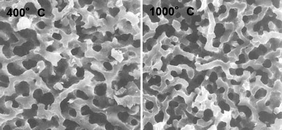
The hydrated silica layers on glass or glass-ceramics, aforementioned, have presumably the same as or similar to the Nakanishi’s mesoporous silica gel in atomic structure. Cho et al. examined the apatite formation on several mesoporous silica gels derived under different additives (polyethylene glycol: PEG and polyacrylic acid: PAA) [25] as well as the formation on those heated up to 1,000 °C [21]. Figure 5.3 shows scanning electron micrographs of the fracture surfaces of the PEG-derived mesoporous silica gels, calcined at 400 and 1,000 °C for 2 h. Entangled pores used to be filled with the solvent and PEG [25]: both have a very similar macroporous microstructure. Strangely enough, the gel from the PEG-containing precursor solution was able to induce the apatite deposition in SBF within 14 days but not the gel from the PAA-containing solution [25]. The PAA gel had a finer entangled microstructure than the PEG gel, while the former exhibited a type I N2 adsorption–desorption isotherms and the latter showed a type IV profile. No other obvious difference was noticed. Among the structural defects, those known as D1 and D2 defects, i.e., four- and three-Si–O-membered cyclic groups, respectively, were detected in both PAA- and PEG-involved gels by Raman spectroscopy, whereas the former defects remained even after soaking both gels in SBF but the latter disappeared on soaking. It was also found that dissolution of Si(IV) from both gels was at the same level, as well as both had almost the same amount of Si–OH groups regardless of being soaked in SBF or not. At this moment, therefore, no definite reasoning or correlation to the structure has been given for the apatite deposition on the mesoporous silica gels depending on the polymers in the precursor solutions. In contrast, the calcining temperature effects superficially seem more straightforward: according to the analyses by Fourier transform infrared spectroscopy and scanning electron microscopy, the gels calcined at 900 °C or above would not deposit any apatite in SBF within 14 days, but the gels calcined at 400 °C or above up to 800 °C deposited apatite. Since dissolution of Si(IV) in 14 days from the gels calcined above 800 °C was half as much as that from the gels calcined at 400–800 °C, such release of Si(IV) species is common among the sol-gel-derived silica and silicate systems. When they are dead-burned, the surface silanol groups are fully condensed. Again, it is the hydrated silica layer that is active to induce apatite deposition in SBF or plasma.
A simple question of knowing the mesoporous silica gels are bioactive is whether those gels are structurally very similar to the hydrated silica layers produced on those bioactive silicate glass or glass-ceramics. No known attempts were made to compare both in terms of their structures, partly because the silica layers are mostly too thin to deserve analyses and partly because the bioactivity of the silica layers is dependent on the calcium ions in the glasses and glass-ceramics.
5.2.2 Apatite Layer Deposition on Ca-Containing Silica Gel Microparticles and Macrospheres
The physiological pH conditions in SBF or blood plasma have greater effects on the apatite deposition or coating as have been discussed in the above sections. Suppose, as Fig. 5.4 schematically represents, that a piece of wet gel that contains calcium ions and is sustainable against severe water corrosion is in contact with a phosphate solution with pH 8–9. Since the gel network is rather open due to incomplete silica condensation with water, the gel provides good ion diffusion paths in all direction through which the calcium ions can migrate. The phosphate ions in the solution (denoted as P(V) in Fig. 5.4) are free to migrate in any direction. As soon as the gel gets contact with the phosphate solution, the calcium ions in the surface region find fellow HPO4 2− and OH− ions, idling in the vicinity of the interface, and hence, those three instantly get together to form apatite crystallites. Soon after this apatite formation procedure has started, the mobile or free Ca2+ ions will be exhausted because the rate of Ca2+ consumption due to apatite formation is far greater than the calcium ion diffusion rate through the gel surface region which is assumed stable. In contrast, the concentration of the phosphate and OH− ions would not change, except at the very vicinity of the reaction zone, because they can migrate very fast in the aqueous solution. This is the case of glass–apatite conversion procedure that the Missouri group (Rahaman, Day, and their co-workers) has reported [62, 63]. This process is totally different from the previous classical Hench–Kokubo–Yamamuro one [2, 5, 6] where the presence of the stable silica layer is prerequisite.
Fig. 5.4
Schematic representation of ion concentration profiles for Ca2+ in glass or gel body and for HPO4 2− and OH− in the phosphate solution. Apatite is formed at the interface (reaction zone) of the material and solution. The arrows show the concentration gradient for each ion soon after the formation reaction has started. The thick arrow for Ca2+ denotes a greater driving force, along the direction of the normal of the concentration profile that enables the preferred Ca diffusion into the surface region. The concentration gradient is established because the rate of calcium ion diffusion is much slower than the rate of Ca consumption due to apatite formation
Being inspired by the glass conversion procedure, Li et al. applied this procedure to apatite coating on silica gel macrospheres [64, 65]. Simple addition of Ca2+ ions into conventional silica gel systems like TEOS–EtOH–H2O with HCl would not yield an improvement in terms of the amount of the calcium ions held in the gel. Basically, the calcium ions are electrostatically interacted with Si–O− and hydrated. Thus, as gelation proceeds, Ca solubility in the gelling silica is reduced, that is, syneresis takes place with the gelation reaction, and the calcium ions are to be squeezed out of the silica body together with the solvent. Hence, it is very likely that almost all calcium ions are absent in the gel body. Li et al. took water glass solution whose pH was adjusted to 3 with HCl as the silica source, into which sodium alginate was added. The mixture was then added dropwisely to calcium chloride solution for the preparation of silica macrospheres. The calcium ions were held as Ca-alginate chelate molecules, and those molecules kept the gel spherical. The gel spheres were subsequently soaked in NH4OH solution for neutralization, before they were soaked in a 1:1 (volume) mixture of 0.1 M Na2HPO4 and EtOH. They expected the reactions at the interface.
![$$ \left[\mathrm{Ca}\ \mathrm{in}\ \mathrm{alginate}\ \mathrm{chelates}\right]+{{\mathrm{HPO}}_4}^{2-}+{\mathrm{OH}}^{-}\to \mathrm{HAp}+\mathrm{alginate} $$](/wp-content/uploads/1008/A312282_1_En_5_Chapter_Equ13.gif)
(5.9)
Indeed, the X-ray diffraction analysis confirmed the apatite deposition on their surface. What was more, the mesopores in the original silica gel macrospheres disappeared when they were soaked in the phosphate solution [64]. Their energy dispersion X-ray (EDX) analysis, presented in Fig. 5.5, showed rather homogeneous Ca and P distribution in the bulk region, while a couple of humps for the Ca and P profiles in the surface region indicated that rigorous HAp deposition took place there.
Fig. 5.5
(a) A scanning electron micrograph shows the surface microstructure of HAp-coated silica gel macrospheres. Flakey crystallites of HAp were observed. (b) Energy dispersion X-ray (EDX) line analysis of the atoms for the fracture surface of the macrosphere. A few humps in the profiles of Ca and P are observed at the surface region (0–30 μm). Ca and P are homogeneously distributed in the bulk region (<30 μm)
Stöber-type silica gel microparticles may hold calcium ions owing to the alkaline moiety of the system. Chen et al. established a Stöber-type system TEOS–EtOH–CaCl2–H2O [66]. A 27Si magic angle spinning (MAS) nuclear magnetic resonance (NMR) analysis indicated [67] both Ca-free and Ca-containing silica gel particles consisted only of Q4, Q3, and Q2 units, and their fractions were ∼70, 30, and ∼1 (mol, %), respectively, regardless of the Ca incorporation. Interestingly, the 27Si CP MAS NMR spectrum of the Ca–silica particles showed the greatly reduced signal intensity (∼1/10) for those Q n units in comparison to the MAS spectrum while the ratio Q4/Q3 remained constant. This simply means that very few protons were present near the Si nuclei, or one can say that the calcium ions pushed away the protons. The bioactivity in terms of apatite deposition in SBF was moderate as the particles gave weak but distinct apatite X-ray diffractions only after soaked in SBF for 5 days or longer. It is natural that the weaker intensity can partly be ascribed to the nano-sized particles: the absolute amount and volume of the apatite were too small.
5.2.3 Self-Catalysis of Aminosilanes and Apatite Deposition
Aminosilanes like aminopropyltriethoxysilane (APTS) and aminopropyldimethylmethoxysilane (APMS) compose a group of surface modifiers owing to their bifunctionality when an aqueous system is established:

(5.10)
This hydrolysis process produces 3 or 2 Si–OH groups and a –NH3 + group on APTS and APMS. Liu and Maciel reported that fuming silica derived from high-temperature (∼660 °C) hydrolysis of SiCl4 in a hydrogen–oxygen flame contains both isolated and hydrogen-bonded silanols on the surface while all silanols in the silica gel body are hydrogen bonded [68]. Therefore, conventional sol-gel-derived silica gels hold so many silanols, and they are susceptible to condensation with those on molecules nearby, that is, they deserve being grafted with such aminosilanes at the silanol end. In contrast, the amino group at the other end would remain associated with the surrounding medium to introduce positive charges on the host silica particles. Pham et al. employed APTS and APMS for surface modifiers to prevent colloidal silica from coagulation [69], while Manzano et al. considered using the amino group for capturing drugs [70]. Grafting onto dry and less reactive surfaces requires the use of piranha solution, like HF–HNO3 [70] or H2SO4–H2O2. Reaction (Eq. 5.10) yields an alcohol molecule ROH as the by-product and releases a hydroxyl ion, as well. The OH ion will favor the condensation of the Si–OH group, that is, self-catalyzed gelation will proceed within the aminosilane system. In a preliminary study, Chen et al. employed this reaction sequence for preparing silica gel spheres coated with a HAp crystallite layer, using APTS as the self-catalyzing silane together with tetraethoxysilane (TEOS) [71].
They obtained only aggregates of component particles, whereas their size was reduced with increase in the mixing ratio TEOS: APTS [72]. Therefore, if an objective is to obtain discrete gel particles with amino-modified surface, postgrafting as Pham et al. [69] took is probably the best way. According to the gelling reaction schemes where the concept of acid and base catalyses works well, the protons favor hydrolysis of Si–OR and the hydroxyls favor condensation [73]; the results above should be interpreted as showing that a greater amount of APTS induces higher pH to stimulate condensation of the Si–OH leading so many nuclei of silica gel, but not showing that APS still disturbs the condensation to suppress size growth. Figure 5.6a shows the surface morphology of those silica microspheres, some of which are fused together to form aggregates. When they soaked those silica particles from the system TEOS-APTS in SBF, Chen et al. found deposition of petallike apatite crystallites agglomerated in hemispheres on the particle surface [72].
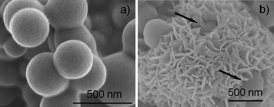
Fig. 5.6
Scanning electron micrographs of silica microparticles (300–400 nm) from the mixture 4.5TEOS-0.45APTS-280H2O-440EtOH (mM). (a) As-prepared. (b) After soaked in Kokubo’s simulated body fluid (SBF) for 7 days. Petallike entities are apatite crystals. One can see a part of the silica microparticles (arrows) (Reproduced from Ref. [72] by permission of John Wiley & Sons Ltd.)
Figure 5.6b shows the morphology of the apatite crystallites that cover the surface of the silica microspheres. In consequence, active amino groups yield many –OH groups in SBF or surrounding medium to stimulate apatite deposition as far as calcium and orthophosphate ions are available.
5.3 Ca–P Formation and Contemporary Glass and Glass-Ceramics
5.3.1 Exploring New Glass and Glass-Ceramics with Apatite-Forming Ability
Bioglass® family has given so great an impact to the bioceramic field that the efforts of exploring new systems still continue. Several examples of glasses or glass-ceramics are listed in Table 5.5 [37, 38, 74–108]. Among those, Anderson et al. pointed out that Al2O3 was incorporated up to 1.5 mass%, without destroying the bioactivity, in their glasses in the 6-component oxide system [74]. The surface hydrolysis of 45S5 and other glasses is one of the key factors for achieving bioactivity. Moritz et al. [77] used a CO2 laser to coat Ti implants with a thin layer (30–40 μm) of their glasses, taking advantage of local heating ability of laser irradiation in a line-scan mode. Zhang et al. reported antibacterial effects of the species dissolved from Ag-free multicomponent bioactive glasses [85]. The antibacterial glasses commonly involve Ag and Cu and sometimes Ce as the dopants [85]. The ability of the dopant-free glasses comes from the increase in local pH and a few ionic species dissolved from the glass granules or particles.
Table 5.5
Examples of exploring new biologically active or bone-bonding glass and glass-ceramicsa
|
Description
|
Typical compositions
|
References
|
|---|---|---|
|
+Al2O3, B2O3 b
|
48SiO2–28Na2O–19CaO–2P2O5–1.5Al2O3–1.5B2O3, etc. (mol %)
|
[74]
|
|
+B2O3, MgO, K2O
|
(<59)SiO2–(14–30)(Na + K)R2O–30(Mg + Ca)O (mol%)
|
|
|
Abo Akademi code 1–93
|
53SiO2–22CaO–6Na2O–11K2O–6P2O5–5MgO–1B2O3 (mass%)
|
[77]
|
|
45S5 typesc
|
(94–2x)SiO2–xNa2O–xCaO–6P2O5; x = 25.5∽19.5 mol%
|
[78]
|
|
45S5 + P2O5
|
45S5 enriched with 0–12 mass % P2O5
|
[79]
|
|
+ MgO, K2O
|
57SiO2–11Na2O–3K2O–15CaO–9MgO–6P2O5, etc. (mass%)
|
|
|
+Na2O, MgO
|
55SiO2•xNa2O•(45 − x)MgO (depositing TCP)
|
[80]
|
|
+MgO, tricalcium phosphate
|
3CaO · P2O5–SiO2–MgO
|
[81]
|
|
+Fe2O3; hyperthermia
|
(FeO, Fe2O3)-CaO-SiO2 glasses: magnetite, wallastonite
|
[82]
|
|
+MnO2, Fe2O3; hyperthermia
|
CaO–P2O5–SiO2–MgO–CaF2–MnO2–Fe2O3
|
[83]
|
|
+ZnO, Fe2O3; hyperthermia
|
x(ZnO, Fe2O3)(65 − x)SiO2•20(CaO,P2O5)• 15Na2O
|
[84]
|
|
Antibacterial activityd
|
76SiO2–22CaO–2P2O5, code S53P4, 45S5
|
[85]
|
|
Electrospinning, precursor sol
|
5P2O5, 25CaO, 70SiO2
|
[86]
|
|
Sol-gel: CaO–SiO2
|
58S (60SiO2•36CaO•4P2O5) (mol%)
|
|
|
58S, acid (citric, acetic, lactic) catalysis on morphology and bioactivity
|
[89]
|
|
|
60S (60SiO2•35CaO•5P2O5) (mass%)
|
[90]
|
|
|
70SiO2, 30CaO (mol%)
|
[91]
|
|
|
Sol-gel silicates
|
||
|
Sol-gel, +Ag2O
|
AgBG (76 SiO2–19CaO–2P2O5–3Ag2O) (mass%),
|
[95]
|
|
(Ag,Na)2O–CaO–2SiO2
|
[96]
|
|
|
MgO, K2O: glass to HA conversion: code 13–93, 1393B1,1393B3
|
53SiO2–6Na2O–12K2O–5MgO–20CaO–4P2O5 (mass %) and the derivatives
|
|
|
+(Na,K)2O, B2O3; code: D-Alk-3B
|
6Na2O–8K2O–8MgO– 22CaO–54B2O3–2P2O5 (mol%)
|
[100]
|
|
Ca-pyrophosphate glass + TiO2
|
60CaO–30P2O5– 3TiO2–7Na2O (mol%)
|
|
|
F-containing glass
|
Crystallization
|
[103]
|
|
F (as NaF) containing glass
|
Derivatives of 50CaO•50SiO2
|
[104]
|
|
F(as CaF2) containing glasses
|
(28–38)SiO2, (4.7–6.3)P2O5, (19–50)CaO, (0, 22–30)Na2O, (4–26)CaF2
|
|
|
F as CaF2 and SrF2, SrO, ZnO
|
(29–44)SiO2–(3–5)P2O5–(20–30)(Ca,Sr)O–(4–33)(Ca,Sr)F2–(13–20)(Na,K)2O
|
[107]
|
|
F (as CaF2)-containing glass
|
46.2SiO2–24.3Na2O–(26.9–x)CaO–2.6P2O5–xCaF2 (x = 0–15)
|
[108]
|
Hong et al. electrospun precursor sols containing poly(ethylene oxide) and a surfactant and calcined the spun fibers to fabricate amorphous nanotubes with thin walls consisting of nano-sized silicate glass particles [86]. Note here that the bioactive glasses from the melt-quenching route contain about 50 mol% SiO2, while those from the sol-gel route have rather greater fractions (60 % or more) of SiO2 [86–96]. Referring to a few examples of sol-gel-derived ternary glasses with bioactivity [91] and the parameters of the sol-gel syntheses, Lei et al. examined the effects of organic acids, such as citric, lactic, and acetic acids, instead of common HCl, on the morphology and dispersion of the silicate glass of a composition, 60SiO2, 36CaO, 4P2O5 (in mol%), which was originally known as 58S [87]. Citric and lactic acids yielded more regular-shaped microspheres with better dispersion and smoother surfaces: those might be preferred in drug delivery applications. Recently, Vaid and Murugavel reported the behaviors of the sol-gel-derived ternary and quaternary Na–Ca silicate systems [94].
5.3.1.1 Effects of Fluoride Ions in Glass
The mother glass of Cerabone A-W® involves F as CaF2 and is subjected to crystallization or devitrification procedure before solid and pore-free bone substitutes are produced. Calliano and Lopez conducted a similar study on crystallization and sintering of F-containing lime silicophosphate glasses [103]. While F can be involved in silicate glasses in two ways, the free ions (ionic F) are coordinated by the corresponding modifier ions, and the other (covalent F) is covalently bonded to Si and P (Si–F or P–F) [104, 109]. The former ones were predominant in the calcium silicate glasses [104]. When F remains ionic in glass, the network connectivity is determined only by the ratio CaO/SiO2. That is, the connectivity is the same as that for the F-free glass. In contrast, the formation of Si–F bonds yields a degraded glass network, comparing with the F-free glass. This may lead to better susceptibility of hydrolysis when in contact with SBF or plasma. Moreover, the ionic F species, or the free fluoride ions, will be incorporated in the apatite lattice to form fluorapatite, which is chemically more stable than ordinary hydroxyapatite. An earlier work by Bauer et al. reported that an increase in the F content in the glass promoted the CaF2 precipitation but suppressed the precipitation of apatite, in comparison to the F-free glass [105]. Bauer et al. [110] suggested that the phosphate content determined the CaF2 and CaCO3 (calcite) formations in the F-containing and F-free glasses, respectively. Lynch et al., in contrast, reported a seemingly contradicting result that a series of fluoride-containing glasses were so active to deposit apatite within 6 h. In consequence, it is surely accepted that we have varied factors to control, such as glass compositions (content of F, P2O5, SiO2, CaO, or other components), the period of soaking the samples in solution, sample size, surface area to solution volume ratio, and solution itself (SBF or other buffer solution), to name a few. Therefore, as Coccihi et al. postulated [108], multivariate data analysis is necessary when one should elucidate reliable conclusions out of individual experiments.
5.3.1.2 Crystallization Yielding Magnetic Glass-Ceramics
Bioglass® 45S5 glass is liable to devitrification on shaping. Moreover, according to a differential thermal analysis to derive Johnson-Mehl-Avrami exponent conducted by Massera et al. [111], 45S5 glass strangely changed the crystallization mode from surface crystallization to bulk one when the grain size increases. Some efforts thus have been paid to fabricate “longer” glass, that is, glasses with better workability or a wider working temperature range [112]. Glass-ceramics involving magnetic phases can be applied to hyperthermia, where the heat evolved from the magnetic phases susceptive to microwave irradiation. A few groups attempted to provide such magnetic glass-ceramics with bioactivity [82–84]. For example, Ebisawa et al. [82] were the first who developed not only magnetic but also bioactive glass-ceramics involving ferrites. Here, the bioactivity was provided by the wallastonite phase precipitated in the course of crystallization. For the hyperthermia cancer therapy, various types of magnetic particles were proposed like hollow and mesoporous silica spheres [113, 114], cobalt ferrite (core)–apatite (shell), and magnetite–apatite composite nanoparticles [115, 116], while Maehara et al. [117] preferred magnesium ferrite (MgFe2O4) to the other ferrites of Cu, Fe (magnetite), Mn, Ni, Sr, or Co. Incidentally, Mother Nature gives us bacterial magnetic particles (BMPs) [118, 119], which are mostly 50–100 nm in size and nowadays are considered for gene therapy or other clinical treatments [120]. It is a key disadvantage in the hyperthermia with magnetized materials that microwave can only penetrate into shallow regions under the skin. In order to overcome this issue, some applicators like antenna or needles have been employed to raise the temperature at deeper region, but a good care is necessary for avoiding burning the skin.
5.3.1.3 Residues of Bioactive Glasses as Stimuli to Gene Activity
In 2001, Xynos et al. reported that the ionic species dissolved from 45S5 Bioglass® should stimulate expression of the genes relevant to human osteoblasts [121]. Then, a movement was emerged [88, 122, 123] to develop third-generation biomaterials that should stimulate the body to heal itself, i.e., cell- and gene-activating materials, in contrast to the previous generation materials that would simply be active only to replace the damaged tissues, to fill up the defects, or to protect from the invasion of cells or tissues harmful for swift recovery. A tendency is emerged to drive researches to develop biodegradable materials from the molecular biology aspect. The materials derived from the sol-gel procedure are advantageous in degradation compared to those via the high-temperature processes such as melt-quenching, sintering, and dead-calcining, since they commonly have many –OH groups due to incomplete calcination. Table 5.5 lists some examples of sol-gel-derived glasses. Unfortunately, against expectations, the sol-gel amorphous materials, like 58S [87], had not yielded statistically significant results in terms of osteoblastic marker gene expression. Note here that although most people praise apparent homogeneity of the sol-gel-derived amorphous materials, the truth is that the atomic distribution in the sol-gel-derived bodies is heterogeneous as far as the multicomponent ones are concerned. This would be justified by the consideration that on the derivation of the sol-gel materials, the alkoxides and inorganic salts are different in the rate of hydrolysis or condensation. In the classic sol-gel science, a few techniques for homogeneous gels were attempted such as prehydrolysis of the components, use of chelating agents, and application of ultrasound [124, 125].
5.3.2 Glass–Apatite Conversion
5.3.2.1 Borate and Borosilicate Glasses to Dense and Hollow Apatite Spheres
Classic model of bioactivity is based on the principle that the material surface should give a metastable hydrated gel layer to serve nucleation sites of apatite deposition [5, 6, 126]. As has been discussed in Sect. 5.2.2, the Missouri group [63, 64, 123, 127, 128] has proposed a method to convert glass into apatite, i.e., to obtain apatite hollow spheres and solid spheres, dependent on the glass composition, at the expense of glass itself. When dissolvable glass containing calcium ions is in contact with a phosphate solution of pH > 8, the chemical state of the glass–solution interface described in Fig. 5.4 will be established. At the beginning, the hydrolysis proceeds at the glass surface to leave a stable hydrated gel. When the surface layer is chemically unstable or dissolved, the calcium ions in the glass are supplied almost freely and ready to precipitate apatite particles. The borate glass derived by substituting B2O3 for SiO2 in 45S5 glass is highly susceptible to the dissolution attack by the alkaline medium, according to the process similar to that described by Eqs. 5.3a and 5.3b, to form a less dense hydrated layer, in which the calcium ions can migrate in all directions to meet the phosphate ones from the solution. That is, calcium borate glass particles are fully converted to polycrystalline hydroxyapatite with random orientation [64] while the borosilicate glass particles are partially converted to yield apatite core–shell glass particles or hollow apatite particles depending on the compositions [123, 127, 128].
5.3.2.2 Conversion of Platelike Calcium Silicate Glasses to Apatite Rod Arrays
In contrast, when a piece of flat calcium silicate glass with moderate dissolvability is in contact with similar phosphate solution, the metastable hydrated layer is sustained as the surface hydrolysis and dissolution of cations proceed. In this situation, the Ca ion supply in the direction parallel to the surface is impractical, being different from the particle case. As a result, established is the Ca2+ ion concentration gradient within the interface region of the glass, the normal of which is perpendicular to the interface. If a large number of reaction sites are available to nucleate the crystallites, the nuclei, earlier produced or comparatively larger ones, will have a freedom to grow. Then nanometer-scale apatite rods will be formed in array perpendicular to the mother glass surface. Indeed, Hayakawa et al. [129] found for a series of soda-lime glasses with lower silica contents, xNa2O–(45−x)CaO–(54 or 55)SiO2, x = 0, 10, 20 (mol%). Among a few glass compositions, a glass-coded G36 (containing 36 % CaO) yielded the most elegant self-assembled apatite nano-rod arrays that grew with an alignment in the direction of the c-axis of the apatite lattice when it was kept in contact with 0.01 M Na2HPO4 at 80 °C for 1 h. The degree of alignment is as high as 0.85, in terms of the measure proposed by Lotgering [130], which was almost equivalent to that of the dental enamel. They could not, unfortunately, detect the hydrated silica layer at the glass–apatite interface. Yet, longer soaking in the phosphate solution fully converted the glass substrates to a block of apatite nano-rod array. Interestingly, when soaked in SBF (Kokubo’s solution), glass G36 gave hemispherical agglomerates of apatite crystallites for which the c-plane grew to give the same petallike morphology as the conventional bioactive silicate glasses or glass-ceramics [13, 18–22].
5.3.3 Apatite Formation on Invert Phosphate Glasses and Glass-Ceramics
Stay updated, free dental videos. Join our Telegram channel
VIDEdental - Online dental courses


