Introduction
Our objective was to identify and evaluate the accuracy and precision (intrarater and interrater reliabilities) of various anatomic landmarks for use in 3-dimensional maxillary and mandibular regional superimpositions.
Methods
We used cone-beam computed tomography reconstructions of 10 human dried skulls to locate 10 landmarks in the maxilla and the mandible. Precision and accuracy were assessed with intrarater and interrater readings. Three examiners located these landmarks in the cone-beam computed tomography images 3 times with readings scheduled at 1-week intervals. Three-dimensional coordinates were determined (x, y, and z coordinates), and the intraclass correlation coefficient was computed to determine intrarater and interrater reliabilities, as well as the mean error difference and confidence intervals for each measurement.
Results
Bilateral mental foramina, bilateral infraorbital foramina, anterior nasal spine, incisive canal, and nasion showed the highest precision and accuracy in both intrarater and interrater reliabilities. Subspinale and bilateral lingulae had the lowest precision and accuracy in both intrarater and interrater reliabilities.
Conclusions
When choosing the most accurate and precise landmarks for 3-dimensional cephalometric analysis or plane-derived maxillary and mandibular superimpositions, bilateral mental and infraorbital foramina, landmarks in the anterior region of the maxilla, and nasion appeared to be the best options of the analyzed landmarks. Caution is needed when using subspinale and bilateral lingulae because of their higher mean errors in location.
Highlights
- •
We determined accuracy and precision of maxillary and mandibular landmarks in 3 dimensions.
- •
These landmarks are to be used in regional superimpositions in 3 dimensions.
- •
Several landmarks had high accuracy and precision; others had large mean errors.
Since the 1930s, cephalometry has been used in orthodontics. A main drawback of cephalometry is that it relies on a 2-dimensional (2D) projection of a 3-dimensional (3D) object, leading to projection and magnification errors. The advent of cone-beam computed tomography (CBCT) addresses some of these shortcomings.
Initially, with the advent of CBCT, there was an interest in demonstrating that cephalometric 2D images derived from CBCT and plain radiograph cephalometry yielded similar results. Many studies compared measurements derived directly from a 3D CBCT cephalogram with traditional 2D cephalograms. Zamora et al found no statistical differences between the measurements of one vs the other. On the other hand, van Vlijmen et al did find different results after a study with a similar question and methodology as those of Zamora et al. One important difference between the 2 studies was how the CBCT cephalometry was read. Zamora et al used multiplanar rendering and 3D rendering CBCT views, whereas van Vlijmen et al used only the 3D rendering CBCT view. Moreover, Grauer et al explains that clear definitions of landmarks in 3 dimensions are required. Lagravère et al agreed with the study of de Oliveira et al with regard to the need for clear definitions but also affirmed that landmarks need to be adjusted in 3D vs 2D cephalometry. Two-dimensional cephalometry points have a definition in 2 axes, but this is not useful in 3D views because of the inclusion of a third axis not defined in the traditional cephalometry. If the 3D view is to be used to its full potential, new and traditional landmarks should be evaluated for ease of use, precision, and repeatability in 3D cephalometry.
Furthermore, they should be as stable as possible over time and be close to the area of interest. Craniofacial structures such as foramina, bony projections, or bony spines, rather than smooth bony surface landmarks such as orbitale and subspinale, should be sought.
The purposes of this study were to identify and to validate bony landmarks in the maxilla and the mandible that are reliably and accurately measured with CBCT.
Material and methods
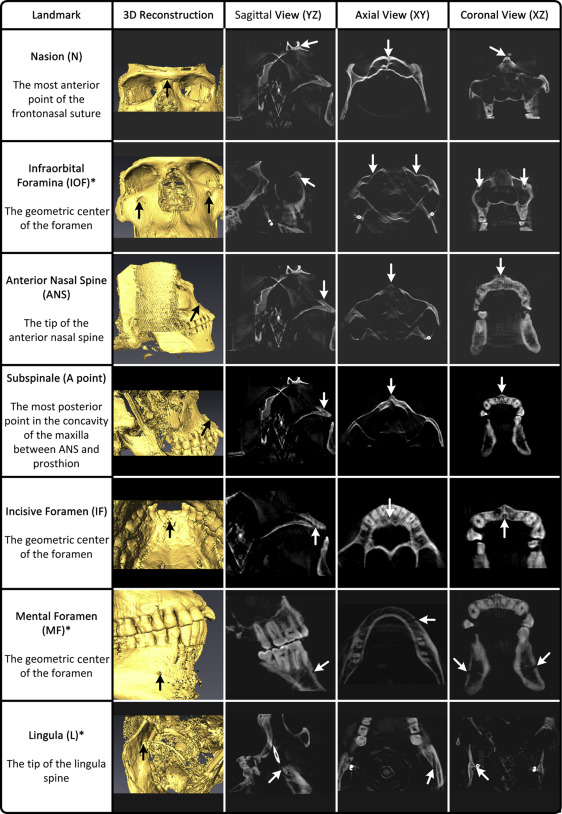
Six anatomic landmarks in the maxilla and 4 in the mandible were selected for this study and are described in Figure 1 . Each landmark is based on easily identifiable anatomic structures that can be potentially used to mark facioskeletal bony structures in cephalometric analyses in CBCT. A visual guide of these landmarks was provided in the multiplanar rendering view (ie, axial, coronal, and sagittal views) and the 3D volumetric rendering view to each reader ( Fig 1 ). These methods of identification have been tested by da Neiva et al. Landmarks were first identified in the axial view using the geometric center of the foramen, the tip of a process, or a bony structure of interest. The landmark location was adjusted until the sagittal, coronal, axial, and 3D views were all in agreement. The group of readers included an experienced orthodontist (M.L.), a senior orthodontic resident, and a dental student.
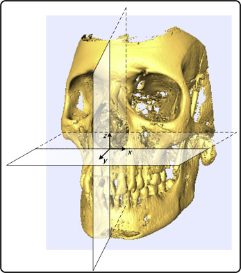
Ten well-preserved, dry skulls with stable occlusion were used in this study. Ethics approval was obtained through the University of Alberta Research Ethics Board. Based on a similar study by Lagravère et al using a similar methodology, the standard deviation of similar CBCT measurements was approximately 0.5 mm. To have a standard error less than 0.2 mm (below the voxel size used in this study), a sample size of 9 was required. In our study, 10 heads were used. The specimens were mounted in a double-layered acrylic plastic box with the outer compartment filled with water to simulate soft tissue attenuation. The specimens were then mounted onto a pedestal inside a CBCT scanner (Next Generation i-CAT; Imaging Science International, Hatfield, Pa). A standardized protocol based on the manufacturer’s specifications of the Next Generation i-CAT was used (field of view, 9 × 12 in; voxel size, 0.30 mm; 120 kVp; 23.87 mAS). Raw images were exported into a DICOM file and were subsequently loaded into Avizo software (version 6.0; Visualization Sciences Group, Burlington, Mass). A Cartesian coordinate system was used throughout where the x-y, x-z, and y-z planes represent the axial, coronal, and sagittal planes, respectively ( Fig 2 ).
To assess precision, intrarater and interrater reliability tests were performed. For the intrarater reliability, each CBCT image was read 3 times at 1-week intervals by the primary investigator (G.L.). Interrater reliability was assessed by 3 readers who read each CBCT once. Each reader was trained with the software.
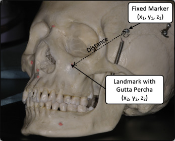
To assess accuracy, CBCT images were obtained for each skull with and without a radiopaque reference (gutta-percha; Dentsply-Maillefer, Tulsa, Okla) placed on the tip of a projection, in the deepest point of a bony concavity, or in the orifice of the foramen of each landmark. The CBCT images were read 3 times by the primary investigator at 1-week intervals. The gutta-percha identified the true location of each landmark and, when compared with the readings done without gutta-percha, provided a measure of accuracy. Two metallic reference markers that were already present on the skulls were used ( Fig 3 ). The distance between the fixed markers and each anatomic landmark was calculated with and without the gutta-percha using the following equation:
d = √(x 2 − x 1 ) 2 + (y 2 − y 1 ) 2 + (z 2 − z 1 ) 2
where d is the distance (mm); x 2 , y 2 , and z 2 are the coordinates of the fixed metallic marker; and x 1 , y 1 , and z 1 are the landmarks of interest as shown in Figure 3 . The accuracy error for each landmark was calculated using this equation:
Accuracy error for 1 landmark = mean of
( Absolute value of ( ( x 2 − x 1 ) 2 + ( y 2 − y 1 ) 2 + ( z 2 − z 1 ) 2 ) − ( ( x 2 − x 1 ∗ ) 2 + ( y 2 − y 1 ∗ ) 2 + ( z 2 − z 1 ∗ ) 2 ) ) + ( Absolute value of ( ( x 2 ∗ − x 1 ) 2 + ( y 2 ∗ − y 1 ) 2 + ( z 2 ∗ − z 1 ) 2 ) − ( ( x 2 ∗ − x 1 ∗ ) 2 + ( y 2 ∗ − y 1 ∗ ) 2 + ( z 2 ∗ − z 1 ∗ ) 2 ) )
Stay updated, free dental videos. Join our Telegram channel
VIDEdental - Online dental courses


