Introduction
Microdamage reduces bone mechanical properties and thus could contribute to implant failure. The objective of this study was to investigate whether the diameter of mini-implants affects linear microcrack generation and whether this differs between the mandible and the maxilla because of their contrasting cortical thicknesses.
Methods
Maxillary and mandibular quadrants of 5 dogs were randomly assigned to receive, in situ, no pilot drilling or mini-implant insertion (control), pilot drilling only without mini-implants, or pilot drilling plus a mini-implant of 1 of 3 diameters: 1.4 mm (n = 18), 1.6 mm (n = 18), and 2.0 mm (n = 18). Linear microcracks were assessed on basic fuchsin-stained sections by using epifluorescence microscopy.
Results
Pilot drilling without mini-implant insertion produced significantly higher linear microcrack burdens in the mandible compared with the maxilla. In the both the mandible and the maxilla, all implants produced higher linear microcrack burdens than did the controls, yet there were no differences between the 3 implant diameters.
Conclusions
Neither the diameter of the mini-implant nor the site of insertion (mandible vs maxilla) had a significant effect on the amount of linear microdamage adjacent to the implant when the implants were inserted after pilot drilling in situ.
The mini-implant has recently emerged as an important modality for orthodontic treatment. Compared with dental implants, mini-implants are relatively small; this allows them to be placed between the dental roots or at various sites in the jaws and to serve as skeletal anchorage for orthodontic tooth movement. However, the success rate of mini-implants is only approximately 85%, which is lower than the rate for dental implants (≥97% in the long term).
Although mini-implant failures have been attributed to various factors, implant diameters and insertion sites (maxilla vs mandible) are commonly cited as important contributors. Whether predrilling is used could also play a role in success or failure. Inserting mini-implants with a small diameter increases their mobility and risk of breakage during insertion. Inserting mini-implants with a larger diameter necessitates higher torque and causes microdamage. Studies have suggested that the failure rate for mini-implants is higher in the mandible than in the maxilla, and that this could be due to differences in the thickness of cortical bone in the mandible. Thicker bone necessitates higher insertion torque, which could cause a greater amount of microdamage, leading to potential mini-implant failure, although data on this are lacking.
Microdamage is a permanent deformation of the bone microstructure. Microdamage in bone acts as a stimulus for bone remodeling, initiating resorption by osteoclasts and new bone formation by osteoblasts. The microdamage burden in bone at any time is the balance between damage formation and damage repair. Whereas microdamage can be repaired under physiologic loading, accumulated microdamage reduces the bone’s mechanical properties. It has been suggested that excessive accumulated microdamage could affect tissue healing and implant failure.
The objective of our study was to investigate whether linear microcracks are related to the diameter of mini-implants and whether this differs between the sites of insertion (maxilla vs mandible). We hypothesized that mini-implants with greater diameters would generate more linear microdamage compared with smaller-diameter implants, and that the mandible would have higher amounts of linear microdamage than the maxilla for a given implant size.
Material and methods
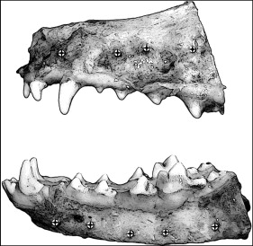
We used 5 mongrel dogs (weight, 20-25 kg; age, 1-1.5 years) that were part of an approved study at our university unrelated to the maxillofacial skeleton. Quadrants of each bone were randomly assigned to 1 of 5 implant groups. Each group received mini-implants with diameters of 1.4 mm (n = 18), 1.6 mm (n = 18), and 2.0 mm (n = 18) after pilot drilling, pilot drilling without mini-implant insertion, or no pilot drilling or mini-implant insertion (control). The maxillary and mandibular quadrants received 4 and 5 mini-implants, respectively ( Fig 1 ). All mini-implants (Rocky Mountain Orthodontics, Denver, Colo) were 6 mm long. After the dogs were killed, the mucosa and the periosteum were reflected, and mini-implants were inserted manually after pilot drilling with a 1.0-mm-diameter surgical drill (Dentaurum, Newton, Pa) with a contra-angle hand piece (Aseptico, Woodinville, Wash) with copious saline-solution irrigation.
After the surgical treatment, each mini-implant, pilot hole, or similar region were sectioned with surrounding bone (approximately 2.0 × 2.0 cm) and immediately fixed in 70% ethyl alcohol for 7 days. The blocks were stained en bloc in 1% basic fuchsin hydrochloride in a graded series of alcohols under vacuum according to standard protocols. The blocks were embedded in methyl methacrylate, sectioned along the mini-implant axis by using an IsoMet low-speed saw (Buehler, Lake Bluff, Ill), and ground and polished to approximately 150 to 160 μm by using a grinding system (Exakt Technologies, Oklahoma City, Okla). The use of basic fuchsin staining allows visualization of microdamage with an epifluorescence microscope (Optiphot 2 microscope; Nikon, Tokyo, Japan) and is essential to differentiate cracks caused from the implant (stained) from cracks formed during grinding and polishing of the histologic slides (unstained).
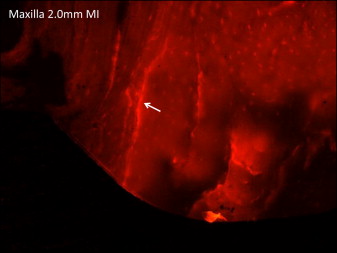
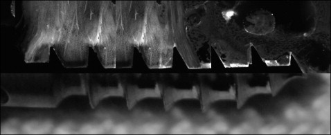
Linear microcracks in the cortical bone adjacent to the mini-implant were identified under an epifluorescence microscope with an excitation wavelength of 546 by using Osteo II software (Bioquant Image Analysis, Nashville, Tenn) according to specific parameters. Specifically, the cracks needed to match these criteria: (1) larger than canaculi but smaller than vascular channels, (2) sharp borders, and (3) upon a change in depth of focus, their edges appeared more deeply stained than the intervening space. Linear microcrack assessment was conducted at 10 times objective magnification ( Fig 2 ) by measuring the crack numbers and lengths and the implant surface length adjacent to the mini-implant ( Fig 3 ). The number of cracks for each implant was summed, and the crack density (number of cracks divided by implant surface length) and the total microdamage burden per surface length (number of cracks × average crack length divided by implant surface length) were calculated. For the group with pilot drilling without mini-implants, microdamage was measured relative to the surface of the pilot hole. For the controls without drilling or mini-implant insertion, microdamage was identified in a general region similar to that of the implants. Cortical bone thickness was also measured by using epifluorescence with 4 times objective magnification. All measurements were made by 1 examiner (E.C.-M.). Intrarater reliability ranged from 0.90 to 0.97 for all parameters based on the intraclass correlation between 2 blinded measurements with a 2-week interval on 10 randomly selected sections.
Statistical analysis
Statistical analyses were performed by using SPSS statistical software (version 19; IBM, Armonk, NY). Unpaired t tests were used to compare the cortical thicknesses of the maxilla vs the mandible. The effects of implant size (1.4, 1.6, and 2.0 mm; pilot drilling; and control), insertion site (4 in the maxilla, 5 in the mandible), and jaw (maxilla or mandible) on microdamage were assessed by using a 3-way analysis of variance (ANOVA). When there were no interactions between the jaw and other factors, separate 1-way ANOVA tests were used to assess differences among implant diameters in each bone. Tukey HSD post-hoc tests were used for paired comparisons when significant differences were observed. Mann-Whitney tests were used to compare the mandible with the maxilla for all treatments combined because of unequal variance between groups for microdamage parameters between the 2 bones. Spearman correlation coefficients were calculated to evaluate the association of cortical thickness with microdamage. For all tests, a P value of <0.05 was used to determine statistical significance. All data are presented as means and standard deviations.
Results
There were no interactions between jaw bone, insertion site, and implant size for any outcome parameter. Overall, the total linear microcrack burden was significantly higher (+53%) in the mandible compared with the maxilla when all conditions (control, pilot drilling only, and the 3 mini-implant sizes) were combined. This was driven by both differences in crack numbers and mean crack lengths (+34% and +37%, respectively). This was completely explained by the differences in linear microcrack parameters between the pilot drilling groups ( Table ). When the mandible and the maxilla were evaluated separately, 1-way ANOVA showed a significant difference among treatment conditions (control, pilot drilling only, and all 3 mini-implant sizes) for both jaws ( Table and Fig 4 ).
| Cortical thickness (μm) ∗ | Implant surface length (μm) ∗ | Number of cracks ∗,† | Crack length (μm) ∗ | Crack density (number of cracks/μm) × 10 −3 | |
|---|---|---|---|---|---|
| Maxilla | |||||
| Control | 1524 ± 528 | 0 ± 0 | 0 ± 0 | 0 ± 0 | 0 ± 0 |
| Pilot drilling | 1913 ± 496 | 4118 ± 1111 ‡ | 0.5 ± 1.41 | 13.99 ± 39.58 | 0.116 ± 0.327 |
| 1.4-mm MI | 1613 ± 751 | 4595 ± 2274 ‡ | 10.5 ± 4.75 ‡,§ | 215.62 ± 63.95 ‡,§ | 2.726 ± 1.915 ‡,§ |
| 1.6-mm MI | 1434 ± 512 | 4422 ± 1852 ‡ | 8.13 ± 4.73 ‡,§ | 209.3 ± 41.65 ‡,§ | 2.138 ± 1.613 ‡,§ |
| 2.0-mm MI | 1492 ± 378 | 4847 ± 1015 ‡ | 11 ± 4 ‡,§ | 248.93 ± 46.79 ‡,§ | 2.413 ± 1.057 ‡,§ |
| Mandible | |||||
| Control | 2437 ± 283 † | 0 ± 0 | 0 ± 0 | 0 ± 0 | 0 ± 0 |
| Pilot drilling | 2466 ± 354 † | 5013 ± 964 ‡ | 4.1 ± 5.65 † | 158.4 ± 149.32 †,‡ | 0.852 ± 1.192 † |
| 1.4-mm MI | 2172 ± 281 | 6296 ± 987 ‡ | 10.4 ± 5.38 ‡ | 213.27 ± 55.23 ‡ | 1.650 ± 0.806 ‡ |
| 1.6-mm MI | 2283 ± 380 † | 6944 ± 1610 †,‡ | 11 ± 6.88 ‡ | 267.75 ± 70.82 ‡ | 1.628 ± 0.916 ‡ |
| 2.0-mm MI | 2269 ± 368 † | 7593 ± 1207 †,‡,§ | 14 ± 6.11 ‡,§ | 283.09 ± 54.04 ‡ | 1.835 ± 0.749 ‡ |
Stay updated, free dental videos. Join our Telegram channel
VIDEdental - Online dental courses


