Introduction
An important objective of orthodontic treatment is to obtain the correct mesiodistal angulation and faciolingual inclination for all teeth. Current techniques are based on crown angulation and inclination standards, and not enough attention has been given to the roots. In this study, we report the mesiodistal angulation and faciolingual inclination of each whole tooth including the root in patients with near-normal occlusion.
Methods
We screened 1840 patients who had cone-beam computed tomography scans taken before treatment to obtain a sample of 76 patients with near-normal occlusion. Using our custom University of Sourthern California root vector analysis software program, we digitized the crown and root centers to determine the “true” long axis of each tooth from where the mesiodistal angulation and the faciolingual inclination were measured.
Results
The means and standard deviations for the mesiodistal angulation and the faciolingual inclination of each whole tooth were calculated. The maxillary angulations of the teeth started from approximately 6° for the central incisors, slightly increased for the lateral incisors, and peaked at 11° for the canines; then it gradually decreased to just above 0° for the first molars and eventually reached −6° for the second molars. The mandibular angulations started from about 0° for the incisors and increased to 17.5° for the second molars. The maxillary inclination was the highest at 33.5° for the central incisors, decreased to about 0° at the second premolars, and then increased for the 2 molars. The mandibular inclination also was the highest at 26.5° for the central incisors, decreased also to about 0° at the second premolars, and continued to decrease for the 2 molars. For the opposing tooth pairs, the interdental mesiodistal angulations always remained within 10° from one another, whereas the interdental faciolingual inclination increased from about 120° for the incisors to about 180° for the second premolars and the 2 molars.
Conclusions
We obtained the average mesiodistal angulation and faciolingual inclination for each whole tooth measured from its long axis digitized on the cone-beam computed tomography volumetric images of 76 patients with near-normal occlusion. We found distinctive angulation and inclination relationships between the neighboring and opposing teeth. This information can be used in addition to the crown standards for positioning each whole tooth properly in the arches.
Orthodontics is the art and science of moving teeth and the associated bone with proper appliances from malocclusion to a stable occlusion with the best possible tooth alignment and function, a change that positively affects facial appearances. Among all the effort of perfecting the orthodontic appliances, probably few surpasses the contributions of Andrews, who studied the stone models of 120 people with optimal tooth alignment and occlusion. He found that, in these subjects, the positions of the same types of teeth among different subjects fell within a narrow range. He also found 6 common features or “keys” that were shared by patients with optimal natural occlusions. Based on these studies, Andrews developed the concept, the treatment goal, and the design of the fully programmed appliances with built-in dimensional and angular features for each type of tooth. Since then, orthodontists have adopted various types of preadjusted appliances to carry out orthodontic treatment with minimum wire bending. Preadjusted appliances were intended not only to treat patients with less effort and more efficiency, but also to improve the quality of the orthodontic finishing. However, even experienced orthodontists still found it difficult to achieve all 6 keys to normal occlusion using preadjusted appliances, mostly because of inaccuracies in bracket positioning during the initial bonding. In addition, the prescriptions for most of these appliances are based on Andrews’s discovery made on the stone model crowns, and not enough attention has been given to the roots. As a result, precise positioning of the whole teeth including the roots at the end of the orthodontic treatment continues to be a challenge.
In accordance with Andrews’s 6 keys to normal occlusion, there are 6 parameters that define the 3-dimensional position of each whole tooth: 4 of them (mesiodistal, faciolingual, and occlusogingival positions, and axial rotation) are dictated by the crown; but 2 others, mesiodistal angulation and faciolingual inclination, involve the root because of variations in crown morphologies, inconsistencies in crown-root angulations, and short crown length relative to root length. Measurement of the mesiodistal angulation and the faciolingual inclination of the whole tooth requires 3-dimensional images of the roots; these have become available only recently. The volumetric images obtained from cone-beam computed tomography (CBCT) scans show the dentofacial structures in a 1:1 ratio, and distortions, if any, are clinically insignificant. However, a valid method to directly measure the mesiodistal angulation and the faciolingual inclination of each whole tooth accurately is still lacking. Several groups have used the coordinate measuring machine to make direct measurements for the typodont teeth, but the coordinate measuring machine cannot be used for patients because its probes cannot be brought into contact with the root apices.
We have reported the use of a custom University of Southern California root vector analysis software program developed with the help of Dolphin (Chatsworth, Calif) to directly measure the mesiodistal angulations and the faciolingual inclinations of the typodont teeth by using their CBCT volumetric images. This study was designed to use this methodology for patients with near-normal occlusion. We hope that this will be the first step toward establishing the mesiodistal angulation and the faciolingual inclination standard for each whole tooth to be used as a guide for designing new orthodontic appliances, as well as for orthodontic treatment planning and finishing.
Material and methods
From April 2004 to October 2009, approximately 1840 patients had full-head CBCT images taken as part of their initial orthodontic records at the Advanced Orthodontic Program of the University of Southern California. A NewTom 3G Volumetric Scanner (NewTom QR, Verona, Italy) was used with the following conditions: 110 kV, 15 mA, 17-second exposure time, 12-in field of view, and 12-bit gray scale. The patients were placed in a supine position, with the teeth in full occlusion and the Frankfort horizontal plane perpendicular to the floor.
The following selection criteria were used for our sample of patients with near-normal occlusion.
- 1.
Photo screening, requiring complete dentition with teeth of generally normal shape and size; molar angle relationship from ≤ a half-step Class II to ≤ a quarter-step Class III; overbite and overjet between 0 and 5 mm; spacing <6 mm, crowding <4 mm, and limited to ≤3 teeth; rotation <15°, limited to ≤3 teeth; dental crossbite limited to 1 tooth and ≤2 mm; and no apparent facial asymmetry and arch-form asymmetry.
- 2.
Radiograph screening, requiring a panoramic radiograph showing generally parallel roots, no missing teeth except the third molars, and no supernumerary teeth; CBCT volumetric image quality from acceptable to good and with teeth in full occlusion; and lateral cephalograms showing ANB between −1° and 6.5°, FMA between 14° and 37°, and interincisal angle between 110° and 146°.
After the initial photo and panoramic radiograph screening, 125 patients remained; 26 patients were removed due to unacceptable quality of their CBCT images, or their teeth were not in full occlusion during the CBCT scanning, or the volumetric view of the occlusion did not meet the requirements of Angle’s classifications. Another 23 patients were removed after the cephalometric criteria were applied. Seventy-six patients eventually remained in the near-normal group.
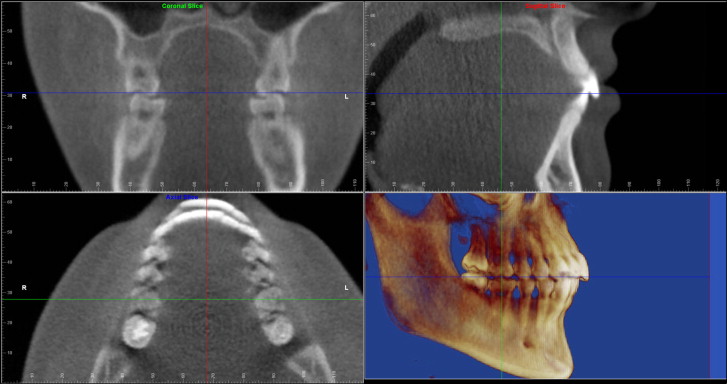
After each patient’s CBCT digital imaging and communications in medicine (DICOM) data were imported and the volumetric image was rendered in Dolphin 3-dimensional program, the maxillary and mandibular global coordinates were first set up for proper orientation of the head and the maxillofacial structures as described in our previous article, with some modifications ( Fig 1 ). Although the sagittal plane and the coronal plane (at the buccal grooves of both maxillary first molars) remained the same, the occlusal plane, defined as the plane that bisects the incisal overbite anteriorly and the molar overbite at the buccal grooves of the maxillary first molars posteriorly, was used for setting up both the maxillary and mandibular transverse planes. These 2 planes were parallel to the occlusal plane at the corresponding crown center levels.
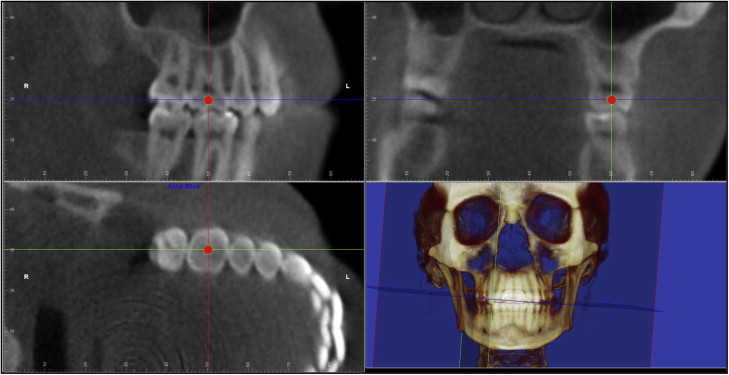
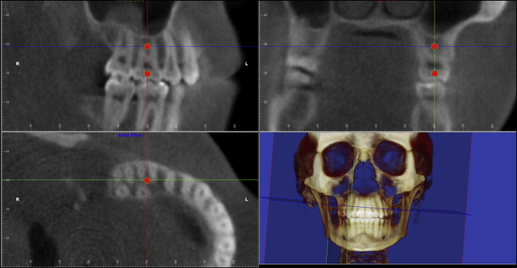
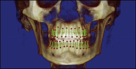
For digitizing the crown and root centers of each tooth, we used a 3-perpendicular-plane coordinate system, with each coordinate specific for only 1 tooth ( Figs 2 and 3 ): the anatomic mesiodistal plane, the anatomic faciolingual plane, and the axial plane at each tooth crown or root center level, respectively. At this point, each tooth to be digitized was treated as if it were an extracted tooth that had no relationship to its neighboring teeth and to either jaw. The tooth images in all 3 perpendicular planes were rotated until the tooth was orthogonal, with the mesiodistal angulation, the faciolingual inclination, and the axial rotation all removed ( Fig 2 ). In the mesiodistal plane view, the tooth was completely vertical with the faciolingual plane and the axial plane intersecting at the center of the crown. In the faciolingual plane view, the tooth was also completely vertical with the mesiodistal plane and the axial plane intersecting at the center of the crown. In the axial plane view, the faciolingual line was vertical, the mesiodistal line was horizontal, and the 2 lines intersected at the center of the crown. A red dot was digitized in the axial views, and it would also simultaneously appear at the crown centers in the other 2 views. For the digitization of the root center, the axial plane was moved to the level of the root center in the mesiodistal or faciolingual plane view. Either the center of a single root or the center of the bifurcation or trifurcation of a double-rooted or triple-rooted tooth was digitized in the axial plane view as shown in Figure 3 . Again, the digitization point would appear at the root center of all 3 views. For the digitization of the next tooth, a different 3-perpendicular-plane coordinate, specific only for that tooth, would be used. The order of digitization was from the maxillary right second molar to the maxillary left second molar, and from the mandibular left second molar to the mandibular right second molar. Figure 4 shows the volumetric image after all teeth were digitized, and the lines connecting the crown and the root centers are the long axes of the teeth.
Digitization of the dental arches and setting up of the tooth-specific coordinate system for the mesiodistal angulation and faciolingual inclination measurements were done with the following method.
First, the maxillary global coordinate system was restored. Four teeth on the right side were digitized in the transverse plane view ( Fig 5 ) along the facial outline of the dental arch: the midincisor, the canine, the second premolar, and the second molar distal. The software program added the mirror image of the digitized right half arch to the left side automatically, constructing a symmetric arch form. The digitization of the mandibular arch was done in the same way after the mandibular global coordinate system was restored.
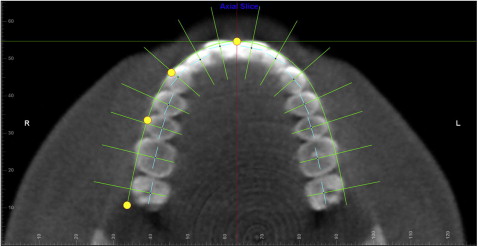
At this point, the custom University of Southern California root vector analysis program automatically constructed another coordinate system composed of multiple 3-perpendicular-plane coordinates, each also specific for only 1 tooth along the dental arch as described in our previous article for the mesiodistal angulation and faciolingual inclination measurements ( Fig 5 ). For all teeth in each arch, the transverse plane was fixed at the approximate crown center level and parallel to the occlusal plane; the straight green line represented the faciolingual plane that passed through each tooth crown center ( small dark blue dot ) and was perpendicular to the dental arch; the short light blue line represented the mesiodistal plane that also passed through each tooth crown center and was perpendicular to the faciolingual plane. The major difference between this tooth-specific coordinate system and the previous one that was used for the digitization of the crown and root centers was that, in the previous one, the 3 reference planes were relative to the anatomy of each tooth, whereas the 3 reference planes for the mesiodistal angulation and faciolingual inclination measurements were relative to the tooth’s position in the dental arch as shown in Figure 5 . Another difference was that the axial plane for each tooth in the previous system was different because of the tooth’s angulation and inclination, whereas the transverse plane in the second tooth-specific coordinate system always remained at the approximate crown center level and parallel to the occlusal plane.
Once the above coordinate system was set up, the custom root vector analysis program used algorithms to measure the mesiodistal angulation and the faciolingual inclination for all teeth automatically.
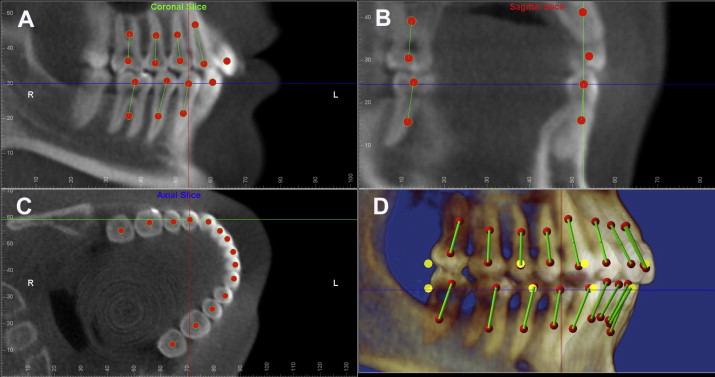
As shown in Figure 6 , A , the mandibular right first premolar’s mesiodistal angulation was measured from the projection of its long axis on the mesiodistal plane to the line of intersection between the mesiodistal and faciolingual planes. If the root center was distal to the crown center, the measurement was positive; otherwise, it was negative. The mandibular right first premolar’s faciolingual inclination was measured from the projection of its long axis on the faciolingual plane to the same intersection line between the mesiodistal and faciolingual planes ( Fig 6 , B ). If the root center was lingual to the crown center, the measurement was positive; otherwise, it was negative. Figure 6 , C , shows the perpendicular relationship between the mesiodistal and faciolingual planes in the transverse plane view. Figure 6 , D , is the 3-dimensional orthogonal view of the mandibular right first premolar from the facial to the lingual.
This study was approved by the University of Southern California, University Park Institutional Review Board (# UP-09-00334).
Statistical analysis
To ensure the reliability of the methodology, 40 subjects were randomly selected and digitized twice more than a week apart: 20 subjects by the same 2 examiners (10 by D.K. and 10 by N.S.); and 20 subjects by 2 different examiners (first digitization all by D.K., second digitization 10 by N.S. and 10 by H.T.). Interexaminer and intraexaminer correlation coefficient tests were performed.
Kolmogorov-Smirnov tests were used to check for normality for all variables. Paired t tests were used to compare the left and right measurements for the parametric variables, and the related-samples Wilcoxon signed rank tests were used to compare the nonparametric variables. The significance level was adjusted for multiple comparisons with the Bonferroni correction to keep the overall type I error at 0.05. All statistics were performed with Excel (Microsoft, Redmond, Wash), SPSS software for Windows, (version 12.0; SPSS, Chicago, Ill), and PASW statistics (version 18; SPSS).
Results
Of the 76 patients with near-normal occlusion, 54 were female, and 22 were male, with an overall average age of 21.5 years (range, 12-36 years; SD, 6.6 years). The ethnic composition was 33 Hispanic, 15 Black, 13 White, 8 Asian, and 7 Middle Eastern.
The mean correlation coefficients for the 20 subjects with 2-time mesiodistal angulation measurements for all teeth were 0.924 (95% CI, 0.896-0.952) by the same examiners and 0.917 (95% CI, 0.891-0.943) by the 2 different examiners; the mean correlation coefficients for the 20 subjects with 2-time faciolingual inclination measurements for all teeth were 0.954 (95% CI, 0.936-0.971) by the same examiners and 0.959 (95% CI, 0.947-0.971) by the 2 different examiners. Since the interexaminers’ and intraexaminers’ correlation coefficients were close and both were less than perfect, to reduce the amount of error, all subjects were digitized a second time, by either the same examiners or different examiners. The averages of the 2-time measurements were used for the analyses.
For the mesiodistal angulations and faciolingual inclinations of all teeth from the 76 patients with near-normal occlusion, the mean values for the right and left teeth, the 2-side average values, and their corresponding standard deviations are shown in Table I . The mean differences between the 2 sides and the P values comparing the 2 sides are also included in Table I . Paired t tests were used except for the maxillary first molar mesiodistal angulation, and the mandibular central and lateral incisors faciolingual inclinations. The data for these 3 teeth had nonnormal distributions, and therefore related-samples Wilcoxon signed rank tests were used. The significance level was adjusted based on the Bonferroni formula to 0.05/14 = 0.00375. Only the maxillary canine mesiodistal angulation, and the maxillary central incisor and the mandibular second premolar faciolingual inclinations showed statistically significant differences between the 2 sides, with mean right and left differences of 1.20°, 0.93°, and 1.35°, respectively. These mean differences were well below the 2.5° for clinical significance. The 2-side measurements matched closely despite statistical differences shown at the 3 tooth locations. Therefore, the 2-side data were combined and averaged ( Table I ).
| Mean, R | SD, R | Mean, L | SD, L | Avg (R, L) | SD, avg (R, L) | Mean dif (R-L) | P value (R and L) | |
|---|---|---|---|---|---|---|---|---|
| Mesiodistal angulation | ||||||||
| U1 | 6.03 | 3.74 | 5.79 | 3.22 | 5.91 | 3.06 | 0.24 | 0.5296 |
| U2 | 7.02 | 3.74 | 6.92 | 4.05 | 6.97 | 3.46 | 0.10 | 0.8165 |
| U3 | 11.99 | 3.76 | 10.79 | 3.33 | 11.39 | 3.21 | 1.20 | 0.0009 ∗ |
| U4 | 8.19 | 4.58 | 7.20 | 4.55 | 7.70 | 4.16 | 0.99 | 0.0247 |
| U5 | 4.41 | 4.12 | 5.01 | 4.30 | 4.71 | 3.80 | −0.60 | 0.1549 |
| U6 | 1.79 | 4.27 | 1.59 | 4.44 | 1.69 | 4.06 | 0.20 | 0.6770 † |
| U7 | −6.86 | 7.39 | −6.09 | 7.26 | −6.33 | 6.98 | −0.77 | 0.0389 |
| L1 | 0.18 | 2.54 | 0.58 | 2.57 | 0.38 | 1.64 | −0.40 | 0.3761 |
| L2 | −0.94 | 3.85 | −0.53 | 3.46 | −0.74 | 3.24 | −0.41 | 0.2918 |
| L3 | 4.70 | 3.81 | 4.24 | 4.26 | 4.47 | 3.71 | 0.46 | 0.2113 |
| L4 | 5.01 | 4.50 | 4.89 | 4.55 | 4.95 | 4.12 | 0.12 | 0.7798 |
| L5 | 7.97 | 3.62 | 8.26 | 3.71 | 8.11 | 3.32 | −0.29 | 0.4262 |
| L6 | 9.82 | 3.37 | 9.45 | 3.38 | 9.63 | 3.09 | 0.37 | 0.2333 |
| L7 | 17.19 | 5.36 | 17.77 | 5.71 | 17.50 | 5.28 | −0.57 | 0.1567 |
| Faciolingual inclination | ||||||||
| U1 | 33.03 | 7.50 | 33.96 | 6.98 | 33.50 | 7.14 | −0.93 | 0.0018 ∗ |
| U2 | 32.02 | 5.91 | 32.70 | 5.05 | 32.36 | 5.29 | −0.68 | 0.0516 |
| U3 | 20.33 | 5.29 | 21.18 | 4.83 | 20.75 | 4.74 | −0.85 | 0.0405 |
| U4 | 5.69 | 5.46 | 6.13 | 5.01 | 5.91 | 4.70 | −0.44 | 0.4063 |
| U5 | 2.41 | 5.04 | 2.21 | 4.69 | 2.31 | 4.27 | 0.20 | 0.7071 |
| U6 | 4.51 | 4.20 | 4.96 | 4.38 | 4.73 | 3.74 | −0.45 | 0.3533 |
| U7 | 10.88 | 5.28 | 10.90 | 5.54 | 10.83 | 4.97 | −0.02 | 0.8704 |
| L1 | 26.54 | 6.13 | 26.34 | 6.35 | 26.44 | 6.16 | 0.20 | 0.2720 † |
| L2 | 25.36 | 5.74 | 25.35 | 5.35 | 25.36 | 5.37 | 0.01 | 0.8680 † |
| L3 | 19.71 | 5.40 | 18.82 | 5.34 | 19.27 | 5.14 | 0.88 | 0.0150 |
| L4 | 8.01 | 4.74 | 7.56 | 4.79 | 7.79 | 4.50 | 0.44 | 0.2267 |
| L5 | −0.24 | 3.94 | −1.58 | 4.08 | −0.91 | 3.59 | 1.35 | 0.0016 ∗ |
| L6 | −7.99 | 4.42 | −9.02 | 4.80 | −8.51 | 4.13 | 1.03 | 0.0322 |
| L7 | −12.09 | 5.22 | −12.80 | 5.40 | −12.38 | 4.92 | 0.71 | 0.2084 |
Stay updated, free dental videos. Join our Telegram channel
VIDEdental - Online dental courses


