Introduction
The objective of this research was to investigate the mechanical properties at both sides of Opus closing loops by analyzing the effects of loop shape, loop position, coil position, and tipping of the vertical legs.
Methods
Opus loops were compared with L-loops (with and without a coil) and a T-loop by using finite element analysis. Both upright and tipped vertical loop legs (70°) were tested. Loop response to loop pulling was simulated at 5 loop positions for a 12-mm interbracket distance and 10-mm loop lengths and heights. Three-dimensional models of the closing loops were created by using beam elements with stainless steel properties. The L-loops and Opus loops were directed toward the anterior side. Loop properties (horizontal load/deflection, vertical force, and moment-to-force ratio) at both loop ends were recorded at activation forces of 100 and 200 g.
Results
Upright Opus loops and L-loops showed the highest moment-to-force ratios (8.5-9.3) on the canine bracket when the loop was centered. The Opus loops and L-loops with tipped vertical legs and the T-loop had slightly lower moment-to-force ratios (7.8-8.5), with the maximum values occurring when the loop was placed close to the canine bracket end.
Conclusions
Upright L-loops showed the highest moment-to-force ratios on canine brackets, whereas backward tipping of the vertical legs shifted mechanical properties closer to those of a T-loop. Loop properties varied with loop configuration and position. Clinicians should understand the specific characteristics of each loop configuration to most effectively exploit them for the desired tooth movements.
Closing loops are used in orthodontics with both segmental and continuous archwires to generate the desired forces and moments to move teeth in a predictable manner. Since no friction is generated between wire and bracket, the force generated by loops can be applied directly to a tooth or a group of teeth. Many closing loop shapes are being used, such as vertical or teardrop loops, T-loops, L-loops, Gjessing springs, and others. These loop types can be further modified by adding a coil, tipping the vertical legs, and so on.
All closing loops have specific mechanical properties (ie, response to mechanical forces), and clinicians need to know these for optimally using them to move teeth or groups of teeth in predetermined directions. The main mechanical loop properties are the moment-to-force ratio, load/deflection, and vertical force. Among these, the moment-to-force ratio can be considered the most significant because it has been related to the type of tooth movement. In the literature, moment-to-force ratios of approximately 10/1 and 7/1 mm are indicated for translation and controlled tipping, respectively. At these relatively high moment-to-force ratio levels, stresses reportedly distribute more evenly through the entire root with minimal changes in the mechanical properties during activation; this reduces injuries to teeth and surrounding tissues.
Researchers and clinicians, therefore, have tried to design and refine loop geometry to obtain as high moment-to-force ratios as possible. Mechanical properties of closing loops depend on many factors, such as loop height, width, shape, position, wire material, cross-sectional dimensions, and so on. Loop height, in particular, affects the moment-to-force ratio considerably. As the loop height increases, the moment-to-force ratio increases. Unfortunately, no loop can reach a moment-to-force ratio greater than its height. Burstone and Koenig reported that a 6-mm-high vertical loop had a moment-to-force ratio of approximately 2, whereas a 10-mm-high vertical loop had a moment-to-force ratio of about 4 for a 7-mm horizontal loop length. For a T-loop, as the gingival-horizontal length increased, the moment-to-force ratio increased to an upper limit and then leveled off. They also showed that loop length and coil had only minor effects on the moment-to-force ratios.
Off-center positioning is also used to modify the moment-to-force ratio. Faulkner et al evaluated T-loops and found that off-center positioning had a significant impact on the moments produced, with a higher moment occurring at the bracket closest to the T-loop. It seemed that the effect of T-loop placement was similar to that of off-centered V-bends, which also produced a greater moment on the closest tooth. Kuhlberg and Burstone reported that a 17-mm interbracket T-loop with a gable bend showed the same characteristics as described above. Consequently, clinicians use loop positions to increase or decrease the moment-to-force ratios.
The shape of a loop is another important factor to adjust the mechanical properties. The moment-to-force ratio generated by T-loops was higher than that of vertical loops with the same loop height. A so-called Opus loop was introduced by Siatkowski. This loop has an L shape with a helix in the apical portion of the L to increase the moment-to-force ratio. Siatkowski reported that the Opus 70 loop, with the vertical legs tipped 70° backward, had a moment-to-force ratio as high as 8.7 mm, which was higher than could be obtained by vertical loops or T-loops with similar dimensions. However, only the mechanical properties for 2 positions (center and approximately 2 mm from 1 end) were reported.
Safavi et al compared the Opus loop with 3 other loop designs (vertical helical loop, T-loop, and L-loop) in 1 eccentric position. Loop height and length were the same 10 mm as in Siatkowski’s studies. However, no information about the interbracket distance and position was provided, except that the loops were placed eccentrically and close to 1 end. Their results showed that an Opus 70 loop could provide a slightly higher moment-to-force ratio than a T-loop. The Opus loop produced moment-to-force ratios of 7.6 and 1.7 mm on the short and long ends, respectively, whereas the T-loop provided moment-to-force ratios of 7.2 and 1.7 mm on the short and long ends. A moment-to-force ratio higher than 8 mm could not be obtained by the Opus 70 loop. No other data are available in the literature to clarify the values of Opus moment-to-force ratios.
The objective of this study, therefore, was to investigate the effect of loop position on the mechanical properties of the Opus loop and other L-shaped loops with a 12-mm interbracket distance by using 3-dimensional finite element analysis. A T-loop was used as the reference. The mechanical properties determined were load/deflection, vertical force, and moment-to-force ratio at both ends of the loops. It was hypothesized that the mechanical properties vary with loop position, loop activation or horizontal reaction force level, and loop shape.
Material and methods
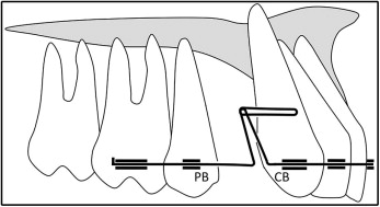
Seven closing loop designs were evaluated in this study: T-loop, L-loop (L90), L-loop with vertical legs angulated 70° to the horizontal portion (L70), L-loop with a coil (LC90), L-loop with a coil and vertical legs angulated 70° to the horizontal portion (LC70), Opus loop (Opus90), and Opus loop with vertical legs angulated 70° to the horizontal portion (Opus70). The T-loop was used as the reference. The designs and dimensions are shown in Figure 1 , A-G . Loop height and width were both 10 mm. The interbracket distance was 12 mm for all designs. The coils for L-loops and Opus loops had a 1-mm diameter. The length simulated the distance between canine and second premolar brackets at the early stage when the first premolar has been extracted ( Fig 2 ).
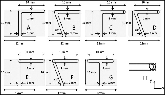
Five a/b ratios (0.17, 0.33, 0.50, 0.67, and 0.83) were investigated ( Fig 3 , A ). In the finite element analysis (MSC.Marc; MSC Software, Santa Ana, Calif), the geometries of the T-loop, L-loops, L-loops with coil, and Opus loops were modeled by subdividing the loops into 520, 440, 520, and 480 elements, respectively. The element segments were 3-dimensional elastic beam elements, each of which was given a 0.016 × 0.022-in rectangular cross-section. These elastic beam elements provided linear interpolation of displacements and rotations in 3 dimensions along their lengths, as well as transverse shear in their cross-sections. The loops were modeled to be planar (x-y plane) under unstressed conditions (unactivated), except for the coil portions, which were modeled out of the plane ( z- direction) ( Fig 1 , H ).
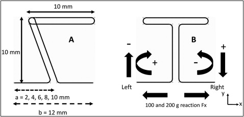
For modeling the loading and fixation, the ends of the closing loops were fixed in 6 degrees of freedom (3 displacements, 3 rotations). During the analysis, both ends were moved 2 mm horizontally in 0.05-mm increments in opposite directions, thereby increasing the total distance between both ends by 4 mm. The horizontal reaction force, vertical force, and moment at both ends were calculated. Directions of vertical force and moment are defined in Figure 3 , B . Positive values of vertical force are directed away from the loop (extrusion), and negative values are in the loop direction (intrusion). Positive moments turn the loop clockwise, negative moments counterclockwise.
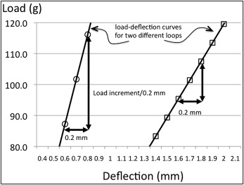
Additionally, the distances between the premolar and canine brackets and the vertical force and moment at both bracket positions were determined under the application of 100 or 200 g of activation force in the x-direction (fixation in the x-direction at the loaded end was removed). The load/deflection value was determined by calculating the tangent of the horizontal reaction load vs the x-deflection curve around the point where a 100-g or 200-g horizontal force was generated ( Fig 4 ).
For modeling the material properties, the beam sections were given the material properties of stainless steel wire. Since the elastic limit for the stainless steel was not exceeded in the simulated activation forces, only the elastic modulus (157.6 GPa) and the Poisson’s ratio (0.3) were required for calculating the deformation and forces in the loop wire.
Results
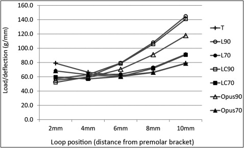
For the T-loop, load/deflection in the horizontal direction under a 100-g force was 61.9 to 79.1 g per millimeter (range, 17.2 g/mm) and changed with loop position ( Table I ; Fig 5 ). The load/deflection ratio was lowest when centered and highest when placed close to either end. For the L90, LC90, and Opus90 loops, load/deflection values varied from 57.1 to 144.8, 52.1 to 141.0, and 55.5 to 117.8 g per millimeter, respectively. Load/deflection values were lowest when the anterior-facing L-loop was close to the premolar bracket side. When moved toward the canine bracket, load/deflection ratios increased and became highest close to the canine bracket side. For the L70, LC70, and Opus70 loops, load/deflections varied from 62.9 to 91.6, 57.0 to 90.8, and 60.3 to 78.8 g per millimeter, respectively. They were lowest when placed at a/b ratios of 0.33, 0.33, and center, respectively. The highest load/deflection ratios were all found when loops were placed close to the canine bracket. Load/deflection values at a 200-g force were nearly the same as at 100 g.
| T | L90 | L70 | LC90 | LC70 | Opus90 | Opus70 | |
|---|---|---|---|---|---|---|---|
| Load/deflection at 100-g reaction force | |||||||
| Position of loop (distance from PB) | |||||||
| 2 mm | 79.1 | 57.1 | 68.3 | 52.1 | 59.5 | 55.5 | 68.3 |
| 4 mm | 66.4 | 63.1 | 62.9 | 60.0 | 57.0 | 58.9 | 62.9 |
| 6 mm | 61.9 | 79.4 | 63.7 | 78.7 | 60.4 | 70.5 | 60.3 |
| 8 mm | 66.4 | 108.0 | 73.0 | 105.8 | 71.8 | 91.0 | 66.1 |
| 10 mm | 79.1 | 144.8 | 91.6 | 141.0 | 90.8 | 117.8 | 78.8 |
| Load/deflection at 200-g reaction force | |||||||
| Position of loop (distance from PB) | |||||||
| 2 mm | 77.3 | 46.2 | 66.3 | 35.5 | 54.7 | 47.4 | 66.3 |
| 4 mm | 63.3 | 48.1 | 60.5 | 39.9 | 52.0 | 49.4 | 60.5 |
| 6 mm | 59.1 | 59.8 | 60.2 | 57.2 | 54.3 | 59.9 | 60.3 |
| 8 mm | 63.3 | 90.2 | 68.9 | 90.2 | 65.6 | 82.5 | 66.8 |
| 10 mm | 77.3 | 139.0 | 90.2 | 136.6 | 89.0 | 116.4 | 81.6 |
Vertical forces created by horizontal forces were zero when the T-loops were centered and maximal when placed close to an end ( Table II ; Fig 6 ). The wire end closest to the loop experienced an extrusion force. For the L90, LC90, and Opus90, vertical forces increased when the a/b ratio increased, generating intrusion forces on the premolar bracket side and extrusion forces on the canine bracket side for a/b ratios. For the L70, LC70, and Opus70, the vertical forces were reversed at a/b ratios between 0.33 and 0.5, 0.17 and 0.33, and 0.33 and 0.5, respectively. Vertical forces increased approximately proportional with the applied horizontal activation forces (100 or 200 g), but the general variations with loop position remained alike.
| T | L90 | L70 | LC90 | LC70 | Opus90 | Opus70 | |
|---|---|---|---|---|---|---|---|
| Vertical force at CB at 100-g reaction force | |||||||
| Position of loop (distance from PB) | |||||||
| 2 mm | −53.5 | 14.0 | −29.9 | 23.5 | −18.2 | 6.4 | −29.9 |
| 4 mm | −33.9 | 40.8 | −9.0 | 45.8 | 3.4 | 31.7 | −9.0 |
| 6 mm | 0.0 | 61.3 | 20.6 | 60.9 | 29.7 | 52.9 | 9.4 |
| 8 mm | 33.9 | 69.7 | 47.6 | 66.3 | 50.9 | 63.6 | 35.6 |
| 10 mm | 53.5 | 68.7 | 61.8 | 64.8 | 60.9 | 64.8 | 52.1 |
| Vertical force at CB at 200-g reaction force | |||||||
| Position of loop (distance from PB) | |||||||
| 2 mm | −104.1 | 14.7 | −60.0 | 33.7 | −39.6 | 3.2 | −60.0 |
| 4 mm | −63.9 | 69.2 | −20.7 | 83.2 | 1.0 | 52.4 | −20.7 |
| 6 mm | 0.0 | 116.9 | 35.2 | 120.6 | 52.7 | 98.1 | 16.9 |
| 8 mm | 63.9 | 138.6 | 89.1 | 133.8 | 97.4 | 122.9 | 66.8 |
| 10 mm | 104.1 | 136.7 | 119.8 | 129.5 | 119.3 | 125.8 | 99.4 |
Stay updated, free dental videos. Join our Telegram channel
VIDEdental - Online dental courses


