Fig. 10.1
Water absorption coefficient and penetration depth of different wavelengths
In addition, the medium infrared lasers (2780–2940 nm) are absorbed also by water in the dentinal walls [28], creating ablation in the dentin when the energy applied is appropriate (see threshold of ablation: Sect. 4.6.1). This is an important topic that differentiates conventional laser use in a dry root canal from activation of the laser in the irrigant (LAI and PIPS). The latter will be explained in more detail in Chap. 11.
Studies were also performed to investigate the ability to induce agitation of liquids using different sources such as pulsed light (optical parametric oscillator) wavelengths of 490–555 nm and Nd:YAG 1064 nm [29, 30].
Levy et al. (1996) found that Nd:YAG laser irradiation induced pressure waves when applied to water-filled root canals. The experiment was performed using the technology available at that time, with different optical fibres (200, 300, 400 and 600 μm) activated in the canal at 50 Hz with power settings of 5, 5.5 and 6.0 W, using an 800 μs pulse duration [31]. The high power used explains the extremely thermal nature of this interaction with the energy delivered by a very long pulse without any affinity of this wavelength with the substrate. In effect, the visible and near-infrared lasers are absolutely not absorbed in water. Hence, no interaction (absorption or diffusion) occurs when the water is irradiated. The laser light is only delivered through the water (transmission), transferring heat if the parameters used are very high.
This was confirmed in a study by Meire et al. (2009) who investigated the antibacterial action of irradiation with different laser wavelengths (Nd:YAG, KTP), photoactivated disinfection (PAD) and 2.5 % sodium hypochlorite (NaOCl) on Enterococcus faecalis bacterial suspensions (in vitro) and in infected tooth models using an aqueous suspension (ex vivo) [32]. These laser systems, at the settings used (Nd:YAG at 1.5 W, 15 Hz; KTP at 1 W, 10 Hz; both with a 200 μm fibre, activated five times during 5 s with 20 s intervals), were less effective than NaOCl in reducing E. faecalis both in vitro and in the infected tooth model. This might be due to poor absorption of the Nd:YAG and KTP wavelengths in water. Meire et al. explained the survival of bacteria, likely with the transmission of the laser beams through the bacterial suspension, rather than absorption. The lack of interaction with the root canal wall when Nd:YAG is activated in NaOCl was also confirmed in the study of Michiels et al. (2010) [33].
Hmud et al. (2010a) tested whether near-infrared 940 and 980 nm diode lasers could induce cavitations in aqueous media [34]. In another study they investigated the temperature variation inside a root canal and outside on the root surface during diode laser irradiation in water-filled canals [35]. At the settings used in these studies (4 W/10 Hz for the 940 nm and 2.5 W/25 Hz for the 980 nm diode lasers, both with a 200 μm optical fibre), the irradiation induced a rise in temperature as much as 30 °C within water inside the canal with only modest temperature changes of 4 °C on the external root surface reported. So, these wavelengths may be explained to act more as heaters rather than activators of the irrigants. In this respect, Deleu et al. (2013) showed that using a high-power diode laser for induction of cavitation may result in areas of carbonisation where the fibre touches the root canal wall dentine [23]. Accordingly, other studies reported more a synergistic effect of 810 and 980 nm diode lasers with NaOCl, EDTA or citric acid rather than an activation of the irrigants in root canals with these substances [36–38]. In the experience of the authors, the 810 and 940 nm diode laser or neodymium:YAG laser (1064 nm) does not induce cavitation effects using present-day advocated clinical parameters. However, using an Nd:YAG laser at 1320 nm, Moon et al. (2012) reported the induction of cavitation bubbles at 1.5 W and 15 Hz. The latter wavelength implies a higher absorption in water or aqueous solutions [39] (see Fig. 10.1).
Finally the CO2 laser operating in the far-infrared spectrum of the light also is highly absorbed by water but is currently not used for root canal treatment because specific tips or fibres are not available.
10.2.2 Laser Target Interaction: Effects on Irrigants
Several studies investigated the fluid dynamics of laser-activated irrigation (LAI) through high-speed visualisation both in free water and in root canal models using Er,Cr:YSGG laser [8, 9] and different Er:YAG lasers [16–18].
The high-speed imaging methods used in these studies enabled to capture images with microsecond resolution, allowing the understanding of the working mechanism of LAI in the root canal.
10.2.2.1 Photothermal Interaction: Heating of the Irrigant
Bubble Formation and Collapse: Expansion and Implosion of Vapour Bubbles in Water
The first effect of the absorption of erbium laser in water is a thermal effect. When the laser energy is absorbed in a layer of water of a few centimetres, an instantaneous superheating of the irrigant to the boiling point of water (100 °C) generates an initial vapour bubble which expands at the tip of the fibre and ends with consecutive implosion [14–18].
Blanken and Verdaasdonk (2007) first described an Er:Cr:YSGG laser generating a vapour bubble that started to expand at a high speed from an opening in front of a flat end firing fibre [14]. They observed that as the laser continued to emit energy, the light passed through the bubble, evaporating the water surface at the front of the bubble, advancing through a channel in the liquid until the pulse ends at about 130 μs (the duration of a single pulse was about 130–140 μs for the Er,Cr:YSGG laser). This mechanism had been previously referred to as “the Moses effect in the microsecond region” by van Leeuwen et al. (1991) [40].
The collapse of the laser-induced bubble follows immediately after the expansion. The shrinkage creates a cavitation-generated pressure wave that travels at supersonic speed (shock wave) in the beginning and at sonic speed (acoustic waves) later [17, 41]. Also a high-speed liquid jet is formed [42] and fluid surrounding the bubble quickly flows inside the decompressed vapour gap, inducing fluid velocities of several metres per second. It was estimated that when an Er,Cr:YSGG is used with a 400 μm flat tip within the canal, fluid movement inside the root canal occurred immediately after each pulse, with fluid speeds up to 20 m/s (72 km/h) [14]. In a following study, Blanken et al. (2009) observed a fluid velocity of 21 m/s using an Er:Cr:YSGG with a 200 μm flat tip at 75 mJ–20 Hz (velocity was calculated based on the measurement of bubble growth and collapse versus time) [15]. Research demonstrated that the dynamics of bubble growth in the root canal model was different from the free-standing water situation [15, 17]. In the root canal model, the lateral expansion is limited by the canal walls. The forward expansion is oscillated by the water in front, while the backward expansion is blocked by the fibre so that pressure inside the bubble remains high for a long time since it has to overtake the resistance of the water in such a small canal. This process delays about three times the dynamics of expansion and implosion compared to the free-water situation as described from Blanken and Verdaasdonk (2007) and Matsumoto et al. (2011) [15, 17].
10.2.2.2 Hydrodynamic Cavitation
Bubbles Cavitation and Shock Waves
Cavitation is defined as “the formation of an empty space (bubble) and fast collapse of a bubble in a liquid” [43, 44].
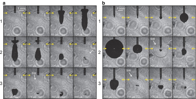
The process is very fast and evolves mainly in the range of 100 μs–1 ms. When a bubble collapses, primary cavitation is formed, followed by secondary cavitation bubbles that create high-speed fluid motions in the canal [15, 16]. The secondary cavitation bubbles are much smaller compared with the first vapour bubble. Also, after the collapse of secondary cavitation bubbles, even smaller bubbles are generated, later disappearing in decreasing numbers [17]. The primary and secondary cavitation bubbles create microjets in the fluid that generate high forces and shear stress along the dentin walls sufficient to remove smear layer and biofilm [15] (Fig. 10.2). In the previous chapter (Chap. 3), the possibility that a laser-induced plasma event through ionisation of the vapour in the induced bubble provides an additional way of cleaning the root canal walls was also reported [45].


Fig. 10.2
Different bubble shape, size and cycle generated by different tips with the same laser device (a) 300 μm Preciso flat tip and (b) X-Pulse conical tip for Er:YAG laser, Fotona (Reprint with permission from Gregorcic et al. [18])
10.3 The Power of the Bubbles: Parameters That Influence Bubble Formation
10.3.1 Effect of Energy
Blanken et al. (2009) and de Groot et al. (2009) observed that the size and the life cycle of a bubble, in free-water environment, depended on the energy applied [15, 16]. These findings are also confirmed by the authors (data not published):
-
The threshold of water vaporisation (the moment of bubble formation) was reached earlier when higher-pulse energy was applied and also continued longer compared to lower energies, explaining the starting time of bubble formation and different cycle time of the bubble.
-
The size of the bubble was larger for higher energies.
-
The dimensions of the bubble were larger for larger-diameter fibres at the same laser energy setting. This finding must be emphasised because this is opposite to the concept of fluence in laser physics.
Table 10.1 reports the energy used in the different LAI studies.
Table 10.1
Studies where the laser fibre of erbium lasers (Er:YAG and Er,Cr:YSGG) is used (1) in the canal and (2) in the pulpal chamber and not referring to photon-induced photoacoustic streaming
|
Wavelength
|
Pulse duration
|
Energy
Pulse
Frequency
Power
|
Tip diameter and shape
|
Position in canal/pulp chamber
|
Apical preparation
ISO
|
Temperature variation
|
Solution
|
Aim
|
Time
|
|
|---|---|---|---|---|---|---|---|---|---|---|
|
Blanken and Verdaasdonk 2007 [14]
|
2780 nm
|
130–140 μs
|
12.5 mJ up to 250 mJ
20 Hz
|
200 μm
320 μm
400 μm
Flat
(Z2, Z3, Z4 Waterlase, Biolase)
|
Glass cylinder 400 μm
Taper 0.06
Length 15 mm
|
5–10 °C
|
Water
|
Visualisation study
Cavitation bubbles
|
5 s
|
|
|
George et al. 2008 [19]
|
2780 nm
|
130–140 μs
|
62.5 mJ
20 Hz
|
400 μm
Conical and flat
MZ4 (Waterlase, Biolase)
|
Apical third
1 mm short of the working length and then activated for 5 s, withdrawing back at 1 mm/s
|
ProTaper F5
Maxillary anterior teeth
|
Distilled water, 3 % hydrogen peroxide and 15 % EDTAC
|
Removal of smear layer
|
10 × 5 s
|
|
|
2940 nm
|
250 μs
|
200 mJ
20 Hz
|
400 μm
Plain and conical
(Kavo Key 3)
|
|||||||
|
Blanken et al. 2009 [15]
|
2780 nm
|
130–140 μs
|
12.5 mJ up to 125 mJ
Increase per 12.5 mJ
20 Hz
|
200 μm
Flat
(Z2 Waterlase, Biolase)
|
Fibre withdrawn out of the canal in 5 s time
|
Glass cylinder 400 μm
Taper 0.06 mm
Length 15 mm
|
Water
|
Visualisation study
Cavitation bubbles
|
5 s
|
|
|
75, 125, 250 mJ
20 Hz
|
Fixed position in the canal
5 mm from the apex
|
Red dye
|
Visualisation study
Removal of dye-coloured water
|
5 s (repeated until clean canal)
|
||||||
|
de Groot et al. 2009 [16]
|
2940 nm
|
250 μs
|
100 mJ
15 Hz
1.5 W
Reduction factor of 0.36
f = 146 mJ mm2
|
280 μm length 30 mm
(Gr. 30 × 28 Kavo Key 2)
|
1 mm short of the working length
Moved slowly up and down 4 mm in the apical half
|
ISO 35
Taper 0.06
Length 15 mm
Decoronated
Maxillary canines
|
2 % NaOCl
|
Debris removal study
Mechanism study
|
20 s
|
|
|
DeMoor et al. 2009 [20]
|
2780 nm
|
130–140 μs
|
75 mJ
20 Hz
1.5 W
|
200 μm
Flat
(Z2 Waterlase, Biolase)
|
Stationary 5 mm short from the apex
|
ISO 40
Taper 0.06
Length 18 mm
Decoronated maxillary canines
|
2.5 % NaOCl
|
Debris removal study
|
4 × 5 s
|
|
|
De Moor et al. 2010 [21]
|
2780 nm
|
130–140 μs
|
75 mJ
20 Hz
1.5 W
|
200 μm
Flat
(Z2 Waterlase, Biolase)
|
Stationary 5 mm short from the apex
|
ISO 40
Taper 0.06
Length 18 mm
Decoronated maxillary canines
|
2.5 % NaOCl
|
Debris removal study
|
4 × 5 s
|
|
|
2940 nm
|
250 μs
|
200 μm
Flat
(Hoya)
|
||||||||
|
Macedo et al. 2010 [6]
|
2940 nm
|
250 μs
|
100 mJ
15 Hz
1.5 W
|
280 μm length 30 mm
(Gr. 30 × 28 Kavo Key 2)
|
1 mm short of the working length
Moved slowly up and down 4 mm in the apical half
|
Apical size and taper not reported
Length 24 mm
Decoronated bovine maxillary central incisors
|
10 % NaOCl
|
Reaction rate of NaOCl
|
1 min activation phase + 3 min resting phase
|
|
|
Matsumoto et al. 2011 [17]
|
2940 nm
|
300 μs
|
30, 50, 70 mJ 20 Hz
Output energy: 11, 18, 26 mJ
|
300 μm cone shaped
18 mm
(R200T Morita)
|
0, 2 or 5 mm short of the bottom
|
Artificial glass root canal model diameter 1 mm
|
Glass beads in water
|
High-speed imaging
|
||
|
50 mJ 1pps
|
5 mm short
|
Artificial model
Free water
ISO 40
|
Visualisation study
|
|||||||
|
Peeters and Suardita 2011 [22]
|
2780 nm
|
130–140 μs
|
28.5 mJ
35 Hz
1 W
|
600 μm
14 mm
Flat
(MZ6 Waterlase, Biolase)
|
In pulp chamber
|
ISO 20–30 taper 0.02
20 mm
Mandibular premolars 20 mm
|
17 % EDTA
|
Smear layer removal study
|
30 and 60 s
|
|
|
Peeters and Mooduto 2013 [46]
|
2780 nm
|
130–140 μs
|
28.5 mJ
35 Hz
1 W
|
400 μm
14 mm
Flat
(MZ4 Waterlase, Biolase)
|
In pulp chamber
|
In vivo small ISO 30
Medium ISO 35–45
Large ISO 50–80
Anterior and posterior teeth
|
2.5 % NaOCl with contrast medium (iomeprol 0.81 g/mL)
|
Apical extrusion
|
60 s: 1 or 2 canals
120 s: 3 or 4 canals
|
|
|
Seet et al. 2012 [51]
|
2780 nm
|
130–140 μs
|
0.25 W
20 Hz
|
Radial firing
(17 mm – 52°)
Diameter n.r.
(Waterlase, Biolase)
|
4 mm in the canal and then withdrawing
|
ISO 40
Taper 0.06
Preparation 1 mm through apex
15 + 1 mm
Single-rooted teeth
|
4 % NaOCl
|
Disinfection study
|
4 × 5 s
Total procedure of 60 s
|
|
|
Kuhn et al. 2013 [60]
|
2940 nm
|
Not mentioned
|
10 mJ
Hz not mentioned
|
300 μm
Flat
(Key Laser 3)
|
From bottom to top at a speed of 1.33 mm/s
|
1.5 mm diameter
Length 20 mm
Acrylic glass plates
|
NaOCl
(4–4.99 % available chlorine)
|
Soft tissue removal study
|
2 s (1.33 mm/s)
7×
|
|
|
Bolhari et al. 2014 [62]
|
2780 nm
|
140 μs
|
1.50 W
2.50 W
20 Hz
|
320 μm
Radial firing
(RTF3 Waterlase)
|
2 mm/s from apex to crown
|
ISO 35
Taper 0.04
14–17 mm length
Single-rooted teeth
|
Distilled water
|
Smear layer removal study
|
3× irradiation at 2 mm/s
|
|
|
Guidotti et al. 2014 [52]
|
2940 nm
|
Not mentioned
|
50 mJ
20 Hz
1 W
Fluence:
7,100 J/cm2 in 5 s
|
300 μm
Flat tip
Preciso
(Fidelis plus 3)
|
Inside the canal exact position not mentioned
|
ISO 30
ProTaper F3
WL not mentioned
Single-rooted teeth
|
3.5 ± 0.4 °C
|
1/2.5 % NaOCL
2/17 %EDTA+
2.5 % NaOCl
3/17 % EDTA
|
Smear layer removal study
|
5 s
1–2–3 cycles
+ Resting time 5 s each
Continuous irrigant flow
|
|
Bago Juric et al. 2014 [64]
|
2780 nm
|
130-140 μs
|
62.5 mJ
20 Hz
1.25 W
|
275 μm
Side firing
(RFT2 Waterlase)
|
5 mm short of WL
|
ProTaper F3
Length 12 mm
Mandibular incisors
Maxillary second premolars
|
2.5 % NaOCl
|
Disinfection study
|
4 × 5 s
|
|
|
Licata et al. 2015 [53]
|
2780 nm
|
140 μs
|
25 mJ and 75 mJ
10 Hz
|
200 μm
Radial firing
25 mm
(RFT2
Waterlase)
|
Stationary at orifice entrance
|
ISO30
Taper 0.06
Length not mentioned
Decoronated single-rooted teeth
|
17 % EDTA
and
5.25 % NaOCl
|
Disinfection study
|
30 and 60 s
|
|
|
Deleu et al. 2015 [23]
|
2940 nm
|
50 μs
|
60 mJ
20 Hz
|
300 μm
Flat
(Preciso 300/14)
AT Fidelis
PIPS
|
5 mm from WL stationary
|
ISO 30
Taper 0.06
WL:1 mm from apical foramen
Maxillary canines
|
2.5 % NaOCL
|
Debris removal study
|
4 × 5 s
|
|
|
40 mJ
20 Hz
|
300 μm
Conical
(PIPS 300/14)
AT Fidelis
|
4 mm in the canal
Stationary
|
4× 5 s
|
|||||||
|
980 nm
|
7.5 W
25 Hz
|
200 μm
Flat
|
2 mm from WL
Moving up and down
|
18 s
|
10.3.2 Effect of Pulse Duration
In addition to the energy used, the duration of the single pulse (from few microseconds to hundred microseconds) is an important parameter that influences the bubble formation and size. The lifetime (or life cycle) of a laser-induced bubble depends on the duration of the single pulse. Different pulse durations of different lasers were investigated. Pulse durations ranging from 140 μs for the Er,Cr:YSGG (Waterlase, Biolase, Irvine, CA, USA) [14, 15] to 250 μs for the Er:YAG (Erwin AdvErl, Morita, Osaka, Japan; Versawave, Hoya ConBio, Fremont, Ca, USA) influenced the start and end duration of the bubble cycle and also its size [17, 18].
Shorter pulses in the range of few microseconds are responsible for a faster start formation of the bubble. Furthermore, shorter pulses are responsible for higher peak power. Accordingly, using very short pulse duration allows for lower energy to create bubble sizes similar to a bubble induced by higher energy with longer pulse duration (data not published).
It is important to underline that the use of energy setting above the threshold of ablation of dentin can produce possible ablative and thermal effects on the dentin walls. The latter is also correlated with irrigant depletion within the canal, easily achieved when energies higher than the energy threshold (of dentin) are used. The short pulse duration of 50 μs is one of the unique features of an advanced laser activation technique, the PIPS technique, which will be presented in the next Chap. 11.
10.3.3 Effect of Pulse Frequency
The pulse frequency (or pulse repetition rate) expresses the number of pulses in 1 s.
Previously reported studies on the mechanism and the efficacy of LAI were performed isolating one single pulse and exploring cavitation through the formation and collapse of the single bubble. The succession of several pulses in 1 s generated more bubbles, and a sequence of several seconds of irradiation even more creates a strong cavitation inside the root canal. No studies were reported on the influence of different pulse frequencies on the efficiency and effectiveness of the irrigant activation. Most of the studies used 20 Hz as pulse repetition rate. In addition, it must be emphasised that the laser used in some of these studies had the pulse frequency fixed at 20 Hz and without any possibility to vary this parameter [14, 15, 20, 21]. de Groot and Macedo utilised 15 Hz [6, 16], while Peeters and Mooduto and Peeters and Suardita 35 Hz [46, 22].
In the author’s experience, frequencies from 15 to 20 Hz are ideal to allow effective cavitation, while higher repetition rates create ineffective overlapping shots, resulting in a standing wave that moves irrigant only close to the end of the tip and not distant as seen with the PIPS technique.
10.3.4 Effect of Different Wavelengths
George et al. (2008) found no difference in performance between the 2780 and 2940 nm laser systems when matched for all other parameters [19].
de Groot et al. (2009) underlined that the size of the laser-generated bubble depended on the absorption by the irrigant according to the wavelength of the laser [16].
De Moor et al. (2010), comparing the effects of Er:YAG and Er,Cr:YSGG wavelengths for activation of the irrigant for smear layer removal, reported similar results with both the wavelengths [21].
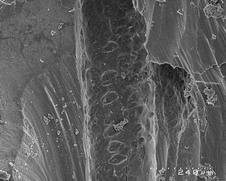
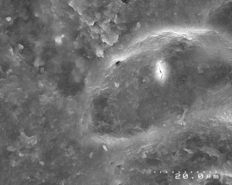
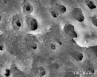
However, from a theoretical point of view, the difference in water absorption of the two different erbium laser wavelengths [26, 27] should suggest that the Er,Cr:YSGG laser, less absorbed in water, requires more energy to generate the same bubble size of an Er:YAG laser. This could be a problem correlated to the higher energy irradiation in the root canal as previously reported (ablative and thermal effect on dentin walls during irrigant depletion) (Figs. 10.3, 10.4 and 10.5).


Fig. 10.3
SEM image of the root canal after LAI performed with an Er,Cr:YSGG laser (2780 nm) equipped with end-firing tip and retracting it up and down, at 1.1 W (75 mJ, 15 Hz). The irrigant vaporisation after few seconds of irradiation caused dry thermal radiation on the dentin walls and ineffective irrigation; note the overlapping hot spot expression of thermal effect (Reprint with permission from DiVito et al. [10])

Fig. 10.4
SEM image of the root canal after LAI performed with an Er,Cr:YSGG laser (2780 nm) equipped with end-firing tip and retracting it up and down, at 1.0 W (50 mJ, 20 Hz). The irrigant depletion caused dry irradiation and successive melting of dentin surface in the apical area

Fig. 10.5


SEM image of the root canal after LAI performed with an Er,Cr:YSGG laser (2780 nm) equipped with end-firing tip and retracting it up and down, at 1.1 W (75 mJ, 15 Hz). The irrigant depletion caused dry irradiation and successive superficial thermal damage on dentin walls (Reprint with permission from DiVito et al. [10])
Stay updated, free dental videos. Join our Telegram channel

VIDEdental - Online dental courses


