Introduction
The purpose of this study was to undertake an exploratory analysis of the relationship among parts in the facial skeleton and cervical vertebrae and their integration as 2-dimensional shapes by determining their individual variations and covariations. The study was motivated by considerations applicable to clinical orthodontics and maxillofacial surgery, in which such relationships bear directly on pretreatment analysis and assessment of posttreatment outcome.
Methods
Lateral radiographs of 61 adolescents of both sexes without major malocclusions were digitized and marked up by using continuous outline spline curves for 8 defined parts in the facial skeleton, including the cervical vertebrae. Individual part variation was analyzed by using principal components analysis, and paired part covariation was analyzed by using 2-block partial least squares analysis in 2 modes: relative size, position, and shape; and shape only.
Results
For individual part variations, cranial base, soft-tissue profile, and mandible had the largest variations across the sample. For covariation of relative size, position, and shape, the cervical vertebrae were highly correlated with the cranial base ( r = 0.80), nasomaxillary complex ( r = 0.70), mandible ( r = 0.74), maxillary dentition ( r = 0.70), and mandibular dentition ( r = 0.74); the maxillary dentition and mandibular dentition were highly correlated ( r = 0.70); the mandible was highly correlated with the bony profile ( r = 0.72), soft-tissue profile ( r = 0.79), and, to a lesser extent, the cranial base ( r = 0.67); the bony profile was highly correlated with the cranial base ( r = 0.70) and soft-tissue profile ( r = 0.80); the soft-tissue profile was highly correlated with the nasomaxillary dentition ( r = 0.81). Covariation of shape only was much weaker with significant covariations found between bony profile and mandible ( r = 0.53), bony profile and mandibular dentition ( r = 0.65), mandibular dentition and soft-tissue profile ( r = 0.54), mandibular dentition and maxillary dentition ( r = 0.55), and bony profile and soft-tissue profile ( r = 0.69).
Conclusions
We found that integration of the shape of parts in the facial skeleton and cervical vertebrae is weak; it is the relative size, position, and orientation of parts that form the strongest correlations.
A standardized lateral radiographic image of the craniofacial skeleton shows a series of discrete, though related, parts comprising skeletal structures and spaces, and the maxillary and mandibular dentitions. The purpose of this study was to undertake an exploratory analysis of the relationship among these parts and their integration as 2-dimensional (2D) shapes by determining their individual variations and covariations. The study was motivated by considerations applicable to clinical orthodontics and maxillofacial surgery, in which such relationships bear directly on pretreatment analysis and assessment of posttreatment outcome. In particular, the ultimate goal was for this type of analysis to become a useful addition and in some cases a replacement for the current uses of standard cephalometric software.
The pursuit of associations between and among parts in the facial skeleton is not a new endeavour. Using standard analyses of lateral headfilms, Solow sought to distinguish between the topographic and nontopographic associations of 2D variables. The former arose from using common reference points or landmarks in measuring each variable. Nontopographic associations, in which common reference points or landmarks were not used, were considered to have biologic significance, although caution was urged to exclude circumstances in which reference points might be placed on a common reference structure. More recently, Enlow and Hans introduced the “counterpart principle” in postnatal facial development studied in sequential lateral head radiographs. This principle states that “the growth of any given facial or cranial part relates specifically to other structural and geometric ‘counterparts’ in the face and cranium.” Enlow and Hans stated that, if each regional part and its counterpart enlarge (grow) to the same extent, balance between the parts and within the face will be maintained.
The methodology in this study relied on techniques used in modern morphometrics, albeit with some differences. The principal object of study was a clinically or diagnostically meaningful part expressed as a shape. We sought to visualize and measure the patterns of covariation among parts in a subject and in a sample of subjects with balanced facial forms and similar maturity, and to determine the variability of such measurements in the sample. Morphometrically, the parts could be regarded as modules being a set of shapes independent, though integrated, through interaction and covariance with other structures during facial development. In this study, a part is a discrete structure, and landmarks (or pseudolandmarks) are defined in relation to the part. Each part is represented by a cubic spline that provides a much richer definition of the part than a finite number of landmarks, although much of the analysis is not crucially dependent on the exact form of the continuous representation of the shape.
The purpose of modularity and integration studies was to investigate the covariation of shape and size during evolution or development, or both. Most such studies used the method of partial least squares (PLS), also known in the morphometrics literature as singular warp analysis. The level of integration between hypothesized shape modules is usually determined by the correlations of corresponding singular warp scores extracted from landmarks, although some studies also use pseudolandmarks, whereas others used more traditional statistical tests on distances and angles measured from landmarks. Typical modules and the corresponding integrations include the following.
- 1.
The face and neurocranium, which are highly integrated across hominid species.
- 2.
The cranial vault, cranial base, and face, where the cranial vault and face are highly integrated in both development and evolution, more so than the vault and base, or the base and face.
- 3.
Integration of the neurobasicranial complex, ethnomaxillary complex, mandible, midline cranial base, lateral cranial floor, and neurocranium.
- 4.
Midline cranial base, lateral cranial base, and face, where the lateral, but not the midline, cranial base and face are highly integrated in contrast to the results reported by Bookstein et al.
- 5.
Midline cranial base, middle cranial fossa, and mandibular ramus, where the midline cranial base and mandibular ramus, and the middle cranial fossa and mandibular ramus showed significant integration, but not the midline cranial base and middle cranial fossa.
- 6.
Mandible, nasomaxillary complex, and neurocranium.
- 7.
cranial base, neurocranium, and face.
This study was intended to extend understanding of the form and architecture of the facial skeleton and investing soft tissues viewed laterally in 2 dimensions, with particular emphasis on parts or modules of clinical interest to orthodontists and maxillofacial surgeons. This study differs from previous studies in several respects: all parts or modules are defined by using free-form curves (cubic splines) because we considered that landmarks lack representational power of the particular parts in question; we investigated the integration of parts in the craniofacial skeleton with the intention of gaining a more complete understanding of craniofacial form, especially in relation to covariation of the parts; we included cervical vertebrae in our analysis to test their relationship to facial form. The ultimate goal was to find the means to study efficiently and informatively the huge repository of lateral headfilms already available from earlier growth and clinical studies.
Material and methods
The sample comprised standard lateral radiographs of a mixed-sex group of North American white adolescents with normal skeletal patterns (n = 61) obtained from a university orthodontic clinic. Patients ranged in dental maturation from the late mixed dentition to the early permanent dentition, with second molars emerging or emerged. Ages and sexes were not given. The headfilms were high-quality digitally rendered x-ray images. All headfilms were taken in natural head position with the lips in repose.
The method relied on the identification and marking up of a series of major parts or modules of the radiographic images of bony structures and the dentition in 2D lateral views. The parts were verified by studying lateral x-ray images of a skull on which metallic markers had been placed to show the most reliable identification of outlines without having recourse to standard landmarks to determine the outlines. The shapes were the following.
- 1.
Cranial base (CRB): CRB shape follows the outline of the superior contour of the cranial base extending from the superior posterior of the frontal sinus to the superior outline of the pituitary fossa, to the dorsal outline of the superior surface of the basicranium to the tip of the clivus.
- 2.
Nasomaxillary complex (NMC): NMC shape follows 3 sides of the composite of the outline of the nasal fossa in the lateral view and the maxillary structure that can be defined reliably where the bony contours are visible radiographically in the lateral view. Beginning at its superior and internal termination, the shape follows down from the upper limit of the pterygomaxillary fossa through the fossa to the posterior limit of the bony palate. It extends from there to an anterior limit approximating the anterior nasal spine and from there superiorly to a point on the inner margin of the image of the nasal bone following the outline of the bony profile.
- 3.
Mandible (MAN): Mandibular shape is delineated by starting at the bony shadow immediately dorsal to the last molar emerged, usually the second molar. The shape is outlined by following the ramus posteriorly and then superiorly along the shadow of the coronoid process, into the mandibular notch, up and around the condylar head and down along the posterior shadow of the ramus to the inferior border of the mandible, and around the external surface of the symphysis to the junction of bone and the foremost incisor.
- 4.
Maxillary dentition (XDE): The shape of the XDE is represented by an outline beginning at the most dorsal point on the shadow of the permanent second molar (emerged or not) and following an outline anteriorly and inferiorly that includes the main features of the crowns of the first molar, premolars, canine, and incisors in profile. From here, the shape includes the labial outline of the foremost incisor to the tip of the root and then follows a line along the root apices until reaching the initial point of the shape.
- 5.
Mandibular dentition (MDE): As in the case of the XDE, this shape is drawn to show the outline of the MDE, including the second molar, in general size and form. Shape delineation is most easily accomplished by following a similar method to that for XDE, starting at a consistent point such as the most dorsal point on the crown of the permanent second molar and proceeding to complete the outline of the MDE.
- 6.
Cervical vertebrae (CVT): Beginning at the superior margin of the odontoid process of the second CVT, the shapes of vertebrae C3 to C5 are followed as a continuous outline from this point inferiorly, around the dorsal shadows of the vertebrae, and across inferiorly to pick up the ventral outlines of the vertebrae. This outline is continued superiorly to close the shape at the point where it began.
- 7.
Bony profile (BPL): Starting from a point on the shadow of the most forward or ventral outline of the frontal bone over the center of the developing frontal sinus, the outline is continued inferiorly through nasion and along the ventral shadows of the nasal bone and the maxilla, through the tip of the anterior nasal spine, and around the mandibular symphysis to its most inferior point.
- 8.
Soft-tissue profile (SPL): From a starting point on the surface of the soft-tissue shadow over the developing frontal sinus, an outline is followed inferiorly to show the shape of the profile of the nose and lips, and the soft tissue over the chin before terminating at a point immediately below the most inferior shadow of the bony symphysis. The lips are in a relaxed state. If the lips touch, then the outline of the upper lip is followed to the touching point, and then on to the lower lip. If the lips do not touch, the upper lip is followed to the foremost incisor and then down to the lower lip.
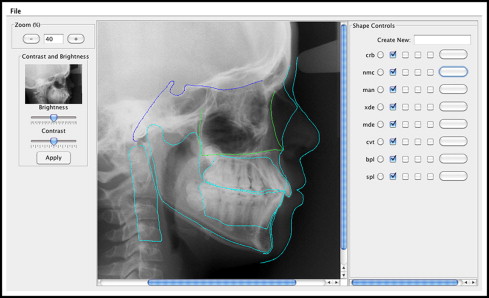
The method used in this study requires the marking up of the parts defined above on an on-screen x-ray image by using software developed especially for the purpose. A screen shot of the prototype software is shown in Figure 1 . When each image was loaded, its magnification, brightness, and contrast were adjusted to obtain the most detailed rendition of a shape. Rather than basing a part on a series of landmarks, continuous outline curves were used to represent shape in the form of Catmull-Rom splines. Catmull-Rom splines are cubic interpolating splines that overcome many limitations of using landmarks. They have the advantages of ease in specification, validity at all scales, and continuity. They can pass through specific landmarks if required and be applied to any continuous shape. Because they are continuous, they cannot easily be used to represent a discontinuous shape such as a square. Consistent with most interpolating spline techniques, the representation is not unique. That is, the same continuous curve can be closely approximated by many differently parameterized Catmull-Rom splines.
A Catmull-Rom spline is defined by a set of control points:
A point on the spline is specified by the parameter 0≤u<1
0 ≤ u < 1
:
P ( u ) = p k-1 ( -s u 3 + 2s u 2 – su ) + p k [ ( 2 – s ) u 3 + ( s – 3 ) u 2 + 1 ] + p k+1 [ ( s – 2 ) u 3 + ( 3 – 2s ) u 2 + su ] + p k+2 ( s u 3 – s u 2 )
Stay updated, free dental videos. Join our Telegram channel
VIDEdental - Online dental courses


