Introduction
Most closing loops designed for producing higher moment-to-force (M/F) ratios require complex wire bending and are likely to cause hygiene problems and discomfort because of their complicated configurations. We aimed to develop a simple loop design that can produce optimal force and M/F ratio.
Methods
A loop design that can generate a high M/F ratio and the ideal force level was investigated by varying the portion and length of the cross-sectional reduction of a teardrop loop and the loop position. The forces and moments acting on closing loops were calculated using structural analysis based on the tangent stiffness method.
Results
An M/F ratio of 9.3 (high enough to achieve controlled movement of the anterior teeth) and an optimal force level of approximately 250 g of force can be generated by activation of a 10-mm-high teardrop loop whose cross-section of 0.019 × 0.025 or 0.021 × 0.025 in was reduced in thickness by 50% for a distance of 3 mm from the apex, located between a quarter and a third of the interbracket distance from the canine bracket.
Conclusions
The simple loop design that we developed delivers an optimal force and an M/F ratio for the retraction of anterior teeth, and is applicable in a 0.022-in slot system.
Highlights
- •
A simple loop design that can produce optimal force and M/F ratio was developed.
- •
Ratio and optimal force level generated in 0.022-in bracket slot system with a combination of activation of a 10-mm-high teardrop loop with reduction in thickness by 50%.
- •
Loop thickness reduction creates distance of 3 mm from apex and loop position between a quarter and a third of the interbracket distance from canine bracket.
There are 2 mainstream methods of space closure in orthodontic treatment after tooth extractions. One is the friction technique, which consists of sliding mechanics wherein a straight archwire slides through the brackets and tubes on the posterior teeth. The other is the frictionless technique, which consists of loop mechanics wherein space closure is achieved by activating closing loops incorporated into an archwire. Because the demand for shortening the treatment period and simplifying the process of archwire bending increases, en-masse retraction with sliding mechanics have more frequently been performed, especially in recent years with the combined use of temporary anchorage devices for improving therapeutic efficiency in orthodontic treatment. Most clinicians who practice sliding mechanics use the 0.022-in slot system because a larger and more rigid archwire is required to prevent undesirable bowing effects during space closure. In sliding mechanics, however, friction is developed at the bracket-wire interface; this may decrease the rate of tooth movement during space closure.
All of the retraction force generated by loops can be directly transmitted to the anterior teeth from the archwire in loop mechanics because of its frictionless mechanism, unlike in sliding mechanics. Therefore, this technique has the potential to produce predetermined moment-to-force (M/F) ratios to accurately achieve controlled movement of the anterior teeth. From the perspective of biomechanics, loop mechanics are still considered a much more efficient technique for achieving the desired type of tooth movement in a predictable manner.
However, a shortcoming of loop mechanics is that the M/F ratio produced by conventionally designed loops made of stainless steel wire is too low to achieve controlled tipping or translation of the anterior tooth. To increase the M/F ratio, several designs of loops in complicated shapes with low load-deflection rates have been fabricated. When the load-deflection rate of the loop is lowered so that the retraction force is decreased, the M/F ratio can be raised because the decrease in the force magnitude is greater than the decrease in the amount of moment.
Another method used to raise the M/F ratio is to place a gable bend in the closing loop. However, a gable bend in a loop could produce an excessively heavy force. Moreover, the use of an archwire with a larger cross-section could generate a greater retraction force in the case of the 0.022-in slot system. Profitt reported that an 8-mm vertical loop in an 0.018 × 0.025-in stainless steel wire produces a retraction force of 500 g per millimeter, which is twice as much as the desired force magnitude for retraction of the anterior teeth. For this reason, most clinicians who practice loop mechanics use the 0.018-in slot system nowadays. If, however, it is desired to use loop mechanics in the 0.022-in slot system, there is a need for an innovative design of a closing loop generating a lighter force and a higher M/F ratio, whose values range from 7 for controlled tipping to 10 for translation of the anterior teeth.
The purpose of this study was to use structural analysis to develop a simple design for a loop that can produce a higher M/F ratio and a gentler force without the addition of gable bends and also improve patient comfort with the 0.022-in slot system.
Material and methods
The forces and moments acting on the ends of the closing loops were determined using a computer program for geometric nonlinear analysis based on the tangent stiffness method, by which large deflections can be handled. This structural analysis has thus enabled determination of the force system generated by closing loops more accurately than the finite element method, which is valid only for small deflections. The basic design of the closing loop examined in this study was a teardrop, 10 mm in height. The interbracket distance was 10 mm, and the loop was bent from 0.019 × 0.025-in or 0.021 × 0.025-in stainless steel wire with Young’s modulus of 200,000 MPa. The teardrop loop configuration was idealized by 62 elements. Assuming that the loop is activated by 1 mm, analysis of the loop is performed by giving forced displacements of 1.0 mm to both ends. Forces and moments acting on both ends of the loop were calculated upon each application of the above-mentioned boundary conditions.
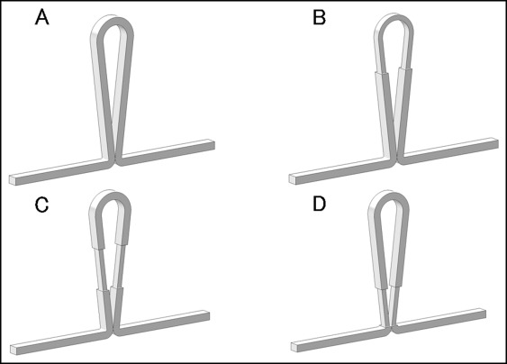
In the first step, the rectangular cross-section of the wire was partially reduced by 30% in both thickness (shorter side) and width (longer side) in different regions (1/3 from the apex of the loop, 1/3 in the middle, and 1/3 from the base) ( Fig 1 ). We calculated the force system produced by the loops and determined which loop design produced the highest M/F ratio. The loops were bent from 0.019 × 0.025-in stainless steel wire and set at a third of the interbracket distance from the canine bracket.
In the second step, forces and moments generated at the loop ends with the partial reduction in the wire cross-section (30% reduction in thickness and width) for 0, 1, 2, 3, 4, and 5 mm from the loop apex were respectively calculated to determine the optimal length of cross-sectional reduction from the apex of the loop fabricated of 0.019 × 0.025-in wire to produce the highest M/F ratio. The loops were placed at a third of the interbracket distance from the canine bracket.
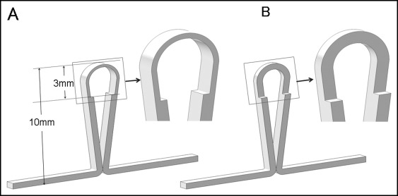
In the third step, the mechanical characteristics of 2 closing loops bent from 0.019 × 0.025-in or 0.021 × 0.025-in wire, in which either the thickness or the width of the cross-section was reduced, associated with various reductions in the wire size by 0%, 10%, 20%, 30%, 40%, or 50%, were analyzed when the loops were placed at a third of the interbracket distance from the canine bracket ( Fig 2 ). The reduced portion extended 3 mm from the apex of the loop. Then, the combination of the site and the rate of reduction in the wire cross-section that produced the highest M/F ratio was determined.
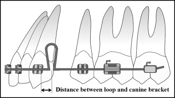
In the fourth step, the forces and moments generated at the loop ends at varying loop positions (1/10, 1/5, 1/4, 1/3, or 1/2 [center] of the interbracket distance from the canine bracket) were calculated to investigate the optimal loop position that generated the highest M/F ratio ( Fig 3 ). In this analysis, 2 wire sizes (0.019 × 0.025 and 0.021 × 0.025 in) were used, and the values of force, moment, and M/F ratio were compared.
Results
Effect of the region of cross-sectional reduction of the loop on the force system
Figure 4 shows the forces, moments, and M/F ratios acting on the ends of the closing loop (10 mm high with a cross-section of 0.019 × 0.025 in), with an activation of 1 mm. When the apical third of the loop was reduced in cross-section ( Fig 4 , B ), the force magnitude was markedly reduced from 357 to 182 g of force. When the cross-section of the middle portion ( Fig 4 , C ) and the basal portion ( Fig 4 , D ) were reduced, forces of 325 and 271 g of force were respectively produced, and the reduction rate of the force was much lower than in Figure 4 , B , in which the cross-section of the apical portion of the loop was reduced. The smallest decrease in moment was observed in Figure 4 , C (from 2019 to 2065 g of force per mm), followed by Figure 4 , B (from 2019 to 1570 g of force per mm), and with the greatest decrease in Figure 4 , D (from 2019 to 1115 g of force per mm).
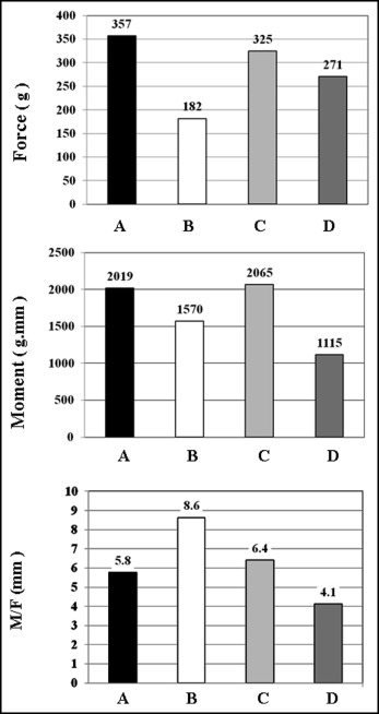
The M/F ratio was substantially increased from 5.8 to 8.6 in Figure 4 , B , in which the apical third of the loop was reduced in cross-section. Although the M/F ratio increased to 6.4 in Figure 4 , C , the amount of the increase was smaller than for Figure 4 , B . By contrast, the M/F ratio decreased to 4.1 in Figure 4 , D .
Effect of the cross-sectional reduction in length from the loop apex on the force system
Figure 5 shows forces, moments, and M/F ratios acting on the ends of closing loop, whose original cross-section is 0.019 × 0.025 in, when varying the length of partial reduction in cross-section from the loop apex by 1, 2, 3, 4, and 5 mm. With the reduction of 1, 2, 3, 4, and 5 mm, the force was decreased from 357 g (for no wire-size reduction) to 197, 185, 182, 181, and 179 g, respectively. Thus, the force decreased as the length of cross-sectional reduction from the apex of the loop was increased.
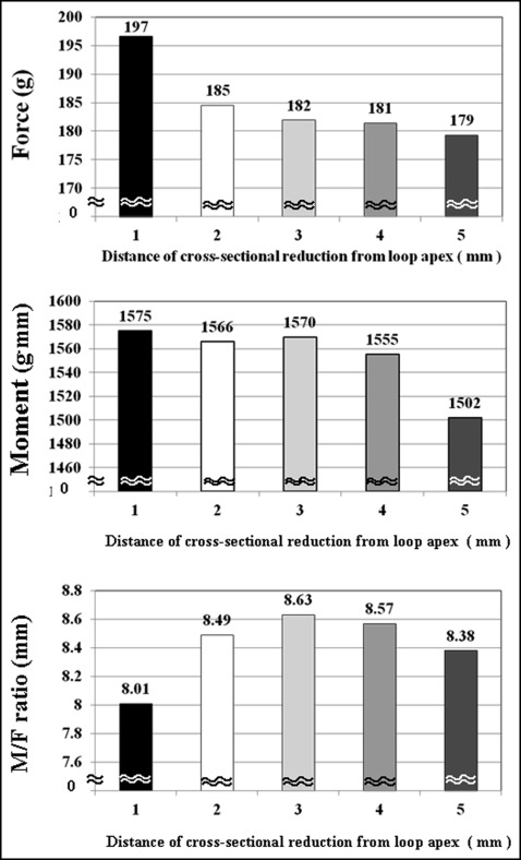
On the other hand, the decrease in moment was less remarkable, up to 4 mm of cross-sectional reduction of the loop, when compared with the decrease in force. The moment was substantially decreased from 2019 to 1502 g of force per mm with a partial reduction of 5 mm. A cross-sectional reduction of 3 mm from the tip of the loop produced the greatest M/F ratio of 8.63, followed by 8.57 for 4 mm, 8.49 for 2 mm, 8.38 for 5 mm, and 8.01 for 1 mm reductions.
Effect of the cross-sectional reduction of the loop by either thickness or width on the force system
Figure 6 shows the forces, moments, and M/F ratios acting on the ends of the closing loop, whose cross-section thickness or width was reduced by 3 mm from the apex, when varying the reduction rate from 0% to 50% at an interval of 10%. Closing loops bent from 0.019 × 0.025-in wire ( Fig 6 , A ) and 0.021 × 0.025-in wire ( Fig 6 , B ) were tested.
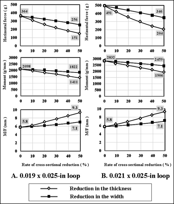
As the reduction rate of the wire cross-section of the 0.019 × 0.025-in loop was increased from 0% to 50%, the force magnitude was decreased from 364 to 151 g with a reduction in wire thickness, and from 364 to 256 g with a reduction in wire width. For the 0.021 × 0.025-in closing loop, the force was decreased from 491 to 204 g with a reduction in wire thickness, and from 491 to 346 g with a reduction in wire width. A similar tendency was observed for the moment. Thus, the moment decreased with an increased reduction rate of the wire cross-section by either thickness or width. However, the decreasing rate of force was much higher than that of the moment. The magnitudes of force and moment generated with the 0.019 × 0.025-in loop were lower compared with the 0.021 × 0.025-in loop at every rate of the wire-size reduction at both sides.
Conversely, the M/F ratio was increased from 5.8 to 9.3 with a reduction in thickness, and from 5.8 to 7.1 with a reduction in width of the wire cross-section when raising the reduction rate of the wire cross-section from 0% to 50%. The M/F ratio was increased by 1.6 times when the thickness of the loop was reduced by 50%, and by 1.2 times when the width was reduced by 50% ( Table ). The values of the M/F ratio for the 0.019 × 0.025-in closing loop were similar to those for the 0.021 × 0.025-in closing loop.
| Rate of reduction in thickness (%) | Rate of reduction in width (%) | |||
|---|---|---|---|---|
| 0 | 50 | 0 | 50 | |
| 0.019 × 0.025-in closing loop | ||||
| Force (g) | 364 | 151 | 364 | 256 |
| Moment (g mm) | 2098 | 1411 | 2098 | 1822 |
| M/F | 5.8 | 9.3 | 5.8 | 7.1 |
| Relative value of M/F ratio (times) ∗ | 1 | 1.6 | 1 | 1.2 |
| 0.021 × 0.025-in closing loop | ||||
| Force (g) | 491 | 204 | 491 | 346 |
| Moment (g mm) | 2832 | 1906 | 2832 | 2459 |
| M/F | 5.8 | 9.3 | 5.8 | 7.1 |
| Relative value of M/F ratio (times) ∗ | 1 | 1.6 | 1 | 1.2 |
Stay updated, free dental videos. Join our Telegram channel
VIDEdental - Online dental courses


