Introduction
Our objective was to evaluate the influence of the expansion screw height of a hyrax expander on the degree of dental inclination during rapid maxillary expansion by using the finite element method.
Methods
The hyrax expander and the maxillary arch were modeled by using Solidworks software (Dassault Systèmes, Paris, France). Three distinct finite element method models were created by simulating different screw heights relative to the plane that intersected the center of resistance of the maxillary first molars. These 3 relative positions were 10 mm below the maxillary first molars’ center of resistance, at the same level as the maxillary first molars’ center of resistance, and 10 mm above the maxillary first molars’ center of resistance. The initial activation of the expanders was simulated, and tooth displacements for each finite element method model were registered in the buccolingual, corono-apical, and mesiodistal directions.
Results
The simulations tested showed that the 3 hyrax screw heights had different dental tipping tendencies. When the screw was simulated below the maxillary first molars’ center of resistance, buccal tipping of the crowns and lingual tipping of the roots were registered. This tendency decreased when the screw was simulated at the same level as the maxillary first molars’ center of resistance. However, when the screw was simulated above the maxillary first molars’ center of resistance, the tipping tendency was inverted, with the crowns displaying lingual tipping and the roots displaying buccal tipping.
Conclusions
These findings might explain the importance of carefully planning the height of the hyrax expander screw, since, depending on this position, different tooth movements can be achieved. From an orthopedic perspective, the ideal screw position might be slightly above the maxillary first molars’ center of resistance; this would generate less dental tipping.
Studies performed since the 1950s have proven the viability of rapid maxillary expansion (RME) and its capacity to aid in the treatment of posterior crossbites, especially in patients with maxillary arch constriction. Various studies have analyzed the effects of RME on the maxilla and its adjacent structures, as well as the forces exerted by the rapid maxillary expanders.
Several authors have stressed the importance of optimizing the orthopedic effects of RME. Buccal inclination of the posterior teeth is an undesired side effect that might limit the amount of orthopedic expansion obtained. Sometimes, RME must be prematurely interrupted to prevent a posterior buccal crossbite without achieving adequate orthopedic correction of the transverse deficiency. Although RME has been widely used in orthodontics for several decades, we still need to better understand its effects and to improve the control of its undesired side effects.
The use of the finite element method is an established and important research tool in dentistry. The finite element method has recently been used to analyze the effects of RME on the teeth and craniofacial bones. Undoubtedly, a major advantage of this research method in the health care field is the possibility of simulating different treatment approaches without exposing animals or humans to any adverse effects of experimental ideas and procedures.
Hyrax and Haas appliances are the 2 rapid maxillary expanders mostly used in orthodontics. Although both expanders generate similar orthopedic effects, many orthodontists prefer to use the hyrax expander because it facilitates the patient’s oral hygiene compared with the Haas expander.
Various studies have analyzed the stresses and strains imposed on the craniofacial complex by RME. However, at present, no studies in the literature have researched the influence of the position of the expansion screw on the orthodontic and orthopedic responses to RME. Therefore, the purposes of this study were to use the finite element method to simulate different hyrax screw heights and to evaluate their influence over posterior tooth inclination during RME.
Material and methods
The construction of the 3-dimensional finite element method model was initiated by using 2-mm sections of a multiplanar computerized tomography scan of a young adult with a complete permanent dentition, except for the third molars. Our research protocol was approved by the ethics research committee of the Pontifical Catholic University of Minas Gerais in Brazil.
A total of 195 computerized tomography images (2-dimensional) were stacked with the computer design software Solidworks with the Simulation package (Dassault Systèmes, Paris, France) to accurately develop the 3-dimensional model. During the development of this model, the maxilla and the teeth were built independently and considered to be independent parts with uniform mechanical properties. The maxillary graphic reproduction was made without considering the maxillary sinus because its anatomic variations would significantly increase the drawing complexity. In addition, the maxilla was drawn up to an upper horizontal limit defined by a plane passing through the anterior nasal spine and the external acoustic meatus on both sides. After all bony structures were graphically represented, each of the 14 teeth was drawn separately, with no differentiation between enamel, dentin, or pulp, and with each tooth considered an independent part.
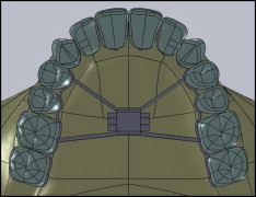
Once the maxilla and the teeth were created, the hyrax expansion screw was modeled in Solidworks based on the measurements of the Palex Mini-12 expansion screw (Dentaurum, Newtown, Pa). The modeled apparatus featured an expansion screw and 2 segments of steel wire that were 0.9 mm in diameter, following the lingual contour of the crowns of the maxillary first and second premolars and the first and second molars ( Fig 1 ).
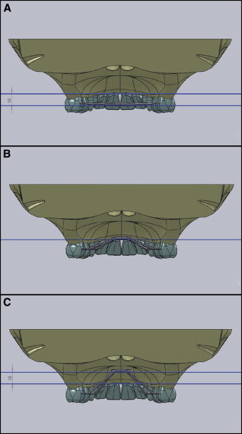
Three distinct finite element method models were created, with different heights of the screw relative to the plane that intersected the center of resistance of the maxillary first molars defined by the furcal region of these 2 teeth ( Fig 2 ). The first model (FEM 1) had the screw positioned in a plane parallel to the occlusal plane that intersected the crowns of the maxillary teeth in the center of their crown, 10 mm below the maxillary first molars’ center of resistance. The second model (FEM 2) had the screw simulated at a higher and intermediate position that was coincident with the plane that intersected the maxillary first molars’ center of resistance. The final model (FEM 3) simulated the screw closer to the palate, 10 mm above the maxillary first molars’ center of resistance ( Fig 2 ).
The frame of the expansion screw was substituted for a frame with a rectangular section. Since a goal of this study was to evaluate the inclinations of the premolars and molars, soft elements were incorporated into the buccal surfaces of the roots of these teeth.
For all 3 models, the materials of both the teeth and the expander were defined. The teeth were considered to have isotropic properties, with an elastic modulus of 21,400 MPa and a Poisson coefficient of 0.31. The expander was defined with the properties of AISI 304 steel from the database of the SolidWorks software, with an elastic modulus of 190,000 MPa and a Poisson coefficient of 0.29. Elastic supports were incorporated into the buccal surfaces of the roots of the teeth, with an elastic constant of 1 × 10⁶ (N/m)/m 2 . A force of 1 N was applied in a direction normal to the medial surface of the body of the apparatus. The values used for the elastic and force constants were standardized across all 3 configurations.
The elastic constant is a way of simulating the resistance to the displacement caused by the labial bone plate. Because there is no value for this resistance in the literature, a standard value was arbitrarily selected. Since this value was not real, the magnitude of the force is relatively unimportant, because this magnitude has been standardized based on our assumed resistance value. Therefore, for the 3 models, meshes were generated with elements measuring 2 mm with a tolerance of 0.1 mm. Static studies were performed, and the tooth displacements for each of the 3 models were registered in the buccolingual (x-axis), corono-apical (y-axis), and mesiodistal (z-axis) directions.
Results
The number of elements and nodes of the mesh for each finite element method model differed because of the different lengths of the screw arms. The model with the lowest configuration (FEM 1) contained 11,378 elements and 19,299 nodes. The model with the intermediate screw position (FEM 2) generated 11,417 elements and 19,414 nodes. The expander simulated with the highest screw position (FEM 3) had a mesh with 11,616 elements and 19,761 nodes.
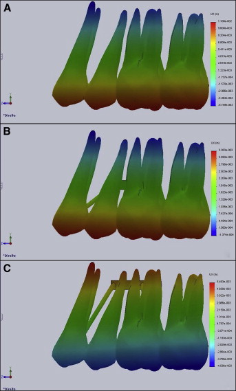
In FEM 1, the crowns of the premolars and molars showed buccal displacements that gradually decreased in the apical-cervical direction. The roots exhibited lingual displacements.
In FEM 2, the crowns of the 4 teeth had displacements in the buccal direction that gradually decreased in the apical-cervical direction. Only the apices of the roots had lingual displacements. The tooth displacements from this configuration were smaller than those registered in FEM 1.
In FEM 3, the tooth crowns displayed displacements in the lingual direction that gradually decreased in the apical-cervical direction. All roots exhibited buccal displacements ( Fig 3 ).
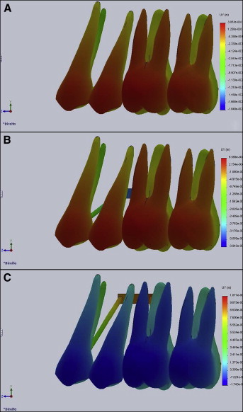
In FEM 1, displacement in the apical-cervical direction was identified for the 4 teeth examined, indicating a tendency toward intrusion.
In FEM 2, there were displacements in the apical-cervical direction of the 4 teeth, indicating a tendency toward intrusion. However, the magnitude of this intrusion tendency was smaller than that registered in FEM 1.
Conversely, in FEM 3, displacement in the coronal direction was identified in the 4 teeth, indicating a tendency toward extrusion ( Fig 4 ).
Stay updated, free dental videos. Join our Telegram channel
VIDEdental - Online dental courses


