FLORIN LĂZĂRESCU
Chapter XII
IN-OFFICE DENTAL CAD/CAM TECHNOLOGY
CAD/CAM technology has become an important field of dentistry and prosthodontics in the last decade, both for laboratory technicians and dentists, as well as for the dental industry. It is the technology of the future that will increase dental therapeutic efficiency, standardize prosthetic restorations, and develop new materials for and concepts of dental treatment.
The many benefits associated with CAD/CAM technologies include a high quality of industrially prefabricated blocks, the standardized quality of restorations, reproducibility made possible by digital technology, spectacular reduction of manufacturing costs, and, not least, access to innovative materials.
The term CAD/CAM is currently being used as a synonym for prosthetic restorations produced by milling technology. A closer look reveals that the acronyms do not provide any information on the method of fabrication: CAD stands for computer-aided design, while CAM is the abbreviation of computer-aided manufacturing. All CAD/CAM systems consist of three components:
• A scanner that converts the collected images into digital data that can be processed by a computer (Fig 12-1).
• Specialized software that processes data and designs restorations.
• A production technology that transforms the data set into a finished product (Fig 12-2).
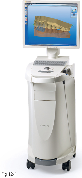
Fig 12-1 CAD/CAM CEREC Bluecam scanner (Sirona).
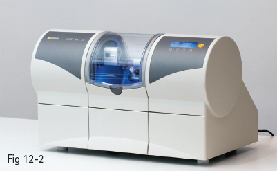
Fig 12-2 CAD/CAM CEREC MC XL dental milling device (Sirona).
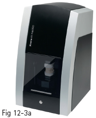
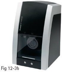
Fig 12-3 a, b CAD/CAM Ceramill – Amann Girrbach. (Images courtesy of Amman Girrbach.)
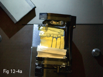
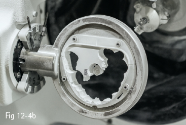
Fig 12-4 a, b CAD/CAM Ceramill – Amann Girrbach. (Images courtesy of Amman Girrbach.)
Depending on the location of the components, CAD/CAM systems can be classified as follows:
• Chairside CAD/CAM systems.
• Laboratory CAD/CAM systems.
• Milling centers.
12.1.1 Chairside CAD/CAM systems
Chairside CAD/CAM systems include a scanner and a milling device (Figs 12-1 and 12-2). The conventional impression is replaced by a digital optical impression, and in most cases the prosthetic restoration is manufactured on the spot, which is a major time-saving advantage.
12.1.2 Laboratory systems
Laboratory systems involve taking a traditional impression and sending it to the laboratory, where the technician fabricates the casts. The casts are scanned and the restorations are manufactured by using the CAD/CAM technique (Figs 12-3a to 12-4b). Of course, it is possible to send an optical impression to the laboratory if it can be taken in the office. Thus, the technician only fabricates the restoration infrastructure and the ceramist finishes it in the traditional manner; or, depending on the material, the final restoration can be milled from the very beginning.
12.1.3 Milling centers
Dental laboratories equipped merely with the optical impression unit send the data set online to a milling center. There is a substantial financial benefit, chiefly for the laboratory, since the purchase of a milling machine is no longer required. The final or core restoration is then sent back to the laboratory. However, it is difficult for the dental practitioner to resort to a milling center, since in most cases the dental laboratory must also be involved (for example, in the manufacturing of bridges), which makes the whole circuit too complicated and ineffective. Essentially, only inlays, onlays, crowns, veneers, and small bridges can be manufactured without the need of the laboratory.
The most important aspect to be taken into consideration in all the above-mentioned cases is that the intraoral data collection system should be open, so that the data set may be read and processed by the various digitization and processing devices available in the dental laboratory.
This chapter deals specifically with chairside CAD/CAM systems (intraoral scanners, milling machines, and materials for processing using in-office CAD/CAM devices).
12.1.4 Scanners
There are two types of scanners:
• Optical scanners.
• Mechanical scanners.
The principle of optical scanners is the collection of data based on triangulation; namely, the source of light and the receptor unit are in a definite angle in their relationship to one another. The angle enables the computer to calculate a three-dimensional (3D) data set from the image on the receptor unit.
Mechanical scanners are based on “line-by-line reading” of the scanned 3D structure. The image is very accurate, but the data set is not easy to process, which makes these devices more difficult to use than optical scanners.1
Intraoral scanning is gaining ground as CAD/CAM technology finds applications in an increasing number of fields: restorative therapy, prosthodontics, implantology, and orthodontics.
Stone models have been and still are the foundation of prosthetic restorations.2 The traditional workflow (impression-taking, casting, restoration) has proven its effectiveness, even taking into consideration the flaws caused by the fact that impression materials are prone to contraction,3 and stone will show expansion due to secondary reactions while setting.4 The aforementioned changes may result in a misfit of the final prosthetic restorations, bringing about forces on the underlying teeth. Natural teeth can move 25 to 100 µm in an axial direction, and 56 to 108 µm in a horizontal direction,5,6 the periodontal ligaments allowing for tiny readjustment in the case of a slight misfit of the prosthetic work. Implants, on the other hand, only show a range of motion of 3 to 5 µm in an axial direction, and 10 to 50 µm in a horizontal direction.6
Changing traditional procedures by replacing tooth impression with intraoral scanning may already eliminate the aforementioned errors in the early stages. Besides these benefits, the short manufacturing time of prosthetic restorations (when scanners are accompanied by milling devices) has resulted in CAD/CAM technology gaining more ground.
At present, there are 11 intraoral scanners available on the market: four made in the USA; two in Germany; two in Israel; and the other three in Italy, Switzerland, and Denmark, respectively.7 All these systems (listed below) have the advantage of producing high-fidelity models and creating 3D archives:
•CEREC – Sirona Dental System (DE).
•iTero – Cadent (IL).
•E4D – E4D Technologies (US).
•Lava COS – 3M ESPE (US).
•IOS FastScan – IOS Technologies (US).
•DENSYS 3D – Densys (IL).
•DPI-3D – Dimensional Photonics International (US).
•3D Progress – MHT (IT) and MHT Optic Research (CH).
•DirectScan – Hint-Els (DE).
•Trios – 3Shape (DK).
Although the scanners use different systems for capturing images (for instance, CEREC AC employs light-stripe projection and active triangulation to generate 3D images,8 Cadent iTero employs a parallel confocal imaging technique for capturing 3D images,9 while Lava COS uses active wavefront sampling to obtain a 3D model of the dentition10), all available systems aim at minimizing image blurring, since the optical properties of the scanned surfaces may affect the accuracy of the scan data.
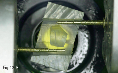
Fig 12-5 MC XL – Sirona milling and grinding unit. (Image courtesy of Sirona.)
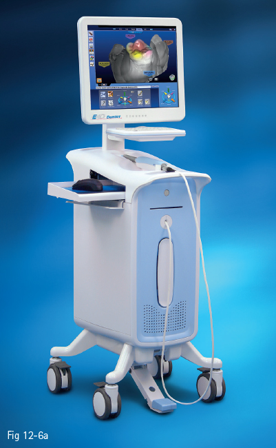
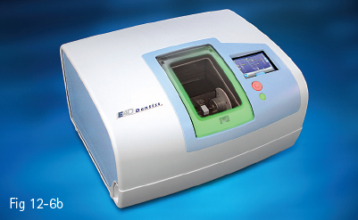
Fig 12-6 a, b E4D system. (Image courtesy of E4D Technologies.)
Certain scanners require that the teeth be dusted with anti-reflective titanium oxide powder (eg, CEREC – with Bluecam, Lava COS), whereas others do not (eg, CEREC – with Omnicam, iTero, Trios, E4D).
12.1.5 Design software
Design software is provided by manufacturers for the design of various dental restorations (inlays, onlays, crowns, bridges, veneers, surgical guides, implant superstructures, telescopic primary crowns). The software is constantly improving, the different generations of CAD/CAM systems being set apart mostly by their construction software, and much less by the changes in impression-taking or processing devices. The data are chiefly stored in STL (standard transformation language), but, as mentioned above, manufacturers may use their own data formats, with the result that data from different construction programs are not compatible with each other.1
12.1.6 Milling machines
Milling machines are distinguished by means of the number of milling axes (three to five). The only chairside systems used in-office are CEREC MC XL (Sirona) and E4D (E4D Technologies) (Figs 12-5 to 12-6b), the others being intended for dental technical laboratories.
There are dry or wet milling procedures. Chairside milling employs a mixture of distilled water and lubricating oil.
12.2 CLINICAL INDICATIONS/TYPES OF RESTORATIONS
As mentioned in the previous section, there are only two systems that include chairside milling machines (CEREC MC XL, Sirona; and E4D, E4D Technologies). Until recently, the major differences between them were related to the fact that the CEREC system required previous dusting of the scanned surface with titanium oxide powder (a problem solved by the Omnicam scanner). Also, data transmission from scanner to milling machine was different: CEREC systems had a constant flow, while it was necessary to press the command button with E4D systems. The following sections mainly focus on the CEREC system, because it is the earliest (over 25 years old) and most widely used, which means that research studies have already been conducted on various types of preparations. Whereas early models of CAD/CAM systems were chiefly used for inlays, onlays, overlays, and veneers, they soon diversified, allowing the fabrication of crowns and bridges, surgical guides, and implant abutments (for implant abutments, the scan must be sent to the dental laboratory).
Due to the relatively limited use of CAD/CAM systems compared to traditional technology, this section calls attention to the research that substantiates the success of this procedure, as well as the materials used, rather than to cavity or tooth preparation techniques, which are similar for all ceramic restorations, and which are extensively described in Chapters IX and X.
12.2.1 Inlays/onlays/overlays
Making these types of restorations using CAD/CAM technology is the choice solution in many clinical situations. Many studies have been conducted in order to test the performance of these types of restorations. In one of them, 2,328 inlays/onlays were placed in 794 patients between 1990 and 1997 (using CEREC 1), and between 1997 and 1999 (using CEREC 2). Microscopic examination of 44 randomly selected restorations revealed an average marginal fit of 236 μm ± 96.8 μm.11 The success rate was 95.5%, and only 35 restorations were lost, mainly because of tooth extraction. No connection between failure and restoration size or location was found (Figs 12-7 and 12-8).
A 15-year comparative study between CEREC inlays, inlays made in the technical laboratory, and gold inlays was conducted at the University of Graz, Austria. Ninety-three gold inlays were cemented using zinc phosphate, 71 gold inlays were bonded, 94 inlays were made in the laboratory (Dicor, Optec, Duceram, Hi-ceram), and 51 inlays were made using CEREC (ceramic Vita Mark I). Forty-nine devitalized teeth were treated: 5 with the gold restorations cemented with zinc phosphate, 14 with bonded gold inlays, 22 with inlays made in the laboratory, and 8 using CEREC.12
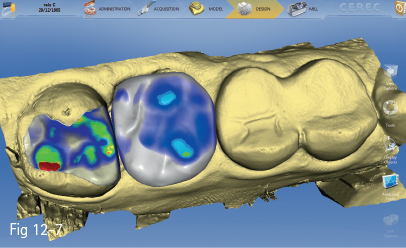
Fig 12-7 Restoration design.
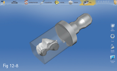
Fig 12-8 Inlay restoration.
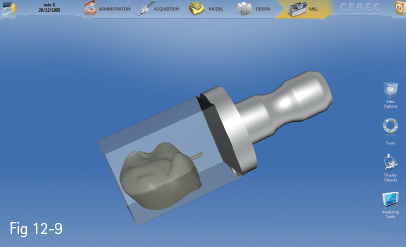
Fig 12-9 Crown restoration.
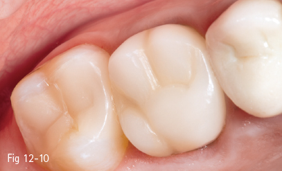
Fig 12-10 Postoperative clinical status.
The following parameters were analyzed; loss or total fracture, partial fracture of the restoration or tooth, decementation, secondary cavity development, and vitality loss. In all study groups, inlays placed on devitalized teeth were found to perform more poorly than those placed on vital teeth. There was not a statistically significant difference between gold and CEREC inlays (~ 93% success rate over 15 years). The performance of laboratory-made inlays was noticeably poorer (68%).
Other studies evaluated the time performance of various types of materials used in lateral teeth restorations. The statistics of annual loss rate provided the following results: glass ionomer (7.7%), amalgam (3.3%), composite fillings (2.2%), composite inlays/onlays (2%), gold inlays/onlays (1.2%), CEREC inlays/onlays (1.1%).13 A high success rate was also reported for overlays. Studies on 286 restorations of this type (Vita Mark II ceramic, CEREC technique) cemented in 244 patients were conducted between 2003 and 2004. The follow-up time was 93 months, and the success rate was 96.5%. A slightly increased risk was found in the case of premolars as compared to molars, and in the mandible as compared to the maxilla.14
12.2.2 Crowns
With the development of the CEREC 2 system, besides inlays and veneers, crowns could also be manufactured (Figs 12-9 and 12-10). Studies on various clinical cases have been conducted, ranging from crown application on vital, short, and devitalized teeth, to an extension of the preparation into the pulp chamber (endocrowns). The highest success rate was documented in the case of conventional preparations (97%), followed by crowns on short teeth (92.9%). The success rate of crowns extended into the pulp chamber was satisfactory in the case of molars (87.1%) and poor in the case of premolars (68.8%). The study comprised 65 all-ceramic Vita Mark II crowns, which were followed up for a period of 4 years.15,16 Other authors reported similar results, namely success rates of 97% regarding margin integrity, absence of secondary cavities, discoloring, and anatomical shape preservation.17
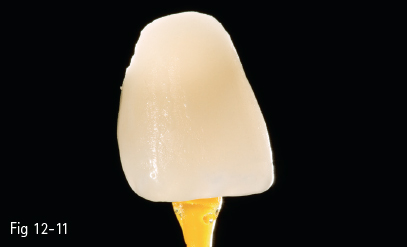
Fig 12-11 Custom-made veneer.
< div class='tao-gold-member'>
Stay updated, free dental videos. Join our Telegram channel
VIDEdental - Online dental courses


