Introduction
The purposes of this study were to evaluate and compare the immediate effects of rapid maxillary expansion (RME) in the transverse plane with Haas-type and hyrax-type expanders by using cone-beam computed tomography.
Methods
A sample of 33 subjects (mean age, 10.7 years; range, 7.2-14.5 years) with transverse maxillary deficiency were randomly divided into 2 groups: Haas (n = 18) and hyrax (n = 15). All patients had RME with an initial activation of 4 quarter turns followed by 2 quarter turns per day until the expansion reached 8 mm. Cone-beam computed tomography scans were taken before expansion and at the end of the RME phase. Maxillary transversal measurements were compared by using the mixed analysis of variance (ANOVA) model and the Tukey-Kramer method.
Results
RME increased all maxillary transverse dimensions ( P <0.0001). There was less expansion at skeletal than dental levels. The hyrax group had greater statistically significant orthopedic effects and less tipping tendency of the maxillary first molars compared with the Haas group.
Conclusions
Both appliances were efficient in correcting a transverse maxillary deficiency. The pure skeletal expansion was greater than actual dental expansion. The hyrax-type expander produced greater orthopedic effects than did the Haas-type expander, but this effect was less than 0.5 mm per side and might not be clinically significant.
Rapid maxillary expansion (RME) is an important method used to correct a transverse maxillary deficiency. It was first described in the literature over a century ago by Angell, and it has been disseminated and made widely popular by Haas since 1961. In RME, rigid and fixed expanders are used to produce heavy forces to obtain the maximum skeletal response by opening the midpalatal suture, with minimum orthodontic movement.
Among the appliances used for RME, the tooth-tissue–borne (Haas-type) and the tooth-borne (hyrax-type) expanders are the most recognized in the literature. The main difference between them is the acrylic pad that leans on the lateral walls of the palatal vault (Haas-type) to reinforce the anchorage for greater orthopedic response and better force distribution during RME. In the hyrax-type expander, there is no acrylic pad; therefore, it is more hygienic and prevents soft-tissue irritation caused by food impaction under the acrylic plate. Although a cephalometric investigation has not demonstrated any differences between Haas-type and hyrax-type expanders, there is no consensus in the literature regarding the differences in the immediate RME effects produced by these appliances.
Several investigations have analyzed the effects of RME through 2-dimensional cephalometric radiographs, which do not allow accurate identification of dentoskeletal structures because of the superimposition of many bones in the different planes of space. To overcome these limitations, computed tomography (CT) for the assessment of the transverse dimensions of the maxilla was introduced by Timms et al in the 1980s. However, the use of conventional CT scans in orthodontics has been limited because of cost and radiation concerns. Cone-beam CT (CBCT) has ushered in a new era in dental diagnostics. This technology was designed for imaging hard tissues of the maxillofacial region with minimum distortion at a lower cost and with lower radiation emissions compared with conventional CT. The high resolution of CBCT images is due to the isotropic voxel (equal in all 3 dimensions), which produces submillimeter resolutions ranging from 0.4 mm to as low as 0.125 mm. Several investigations have shown the high accuracy of CBCT images for quantitative and qualitative analyses. Its use is recommended in orthodontics for several purposes such as evaluation of impacted teeth, evaluation of bone grafts in cleft regions, analysis of alveolar bone before placement of orthodontic temporary anchorage devices, and evaluation of RME effects on nasomaxillary structures.
The purposes of this study were to evaluate and compare the immediate effects of RME on the transverse plane with Haas-type and hyrax-type expanders by using high-resolution CBCT.
Material and methods
This study was approved by the ethical committee of the Pontifical Catholic University of Rio Grande do Sul in Brazil. Informed consent was obtained from the parents of all patients who agreed to participate in this study. The sample was selected by examining subjects in need of orthodontic treatment at the Department of Orthodontics of the School of Dentistry. The inclusion criteria for this study were transverse maxillary deficiency, mixed dentition or early permanent dentition, and no surgical or other treatment that might affect the RME effects during the expansion period. Patients with congenital malformations or periodontal diseases, or above 15 years of age were excluded from the study sample.
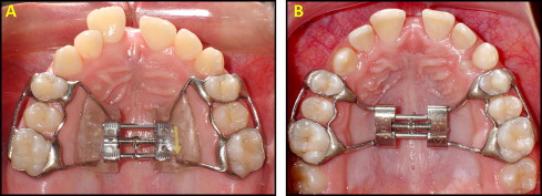
In this prospective study, the sample comprised 33 healthy white children (11 boys, 22 girls) with a mean chronologic age of 10.7 years (range, 7.2-14.5 years) and a mean skeletal age of 10.9 years (range, 6.8-15 years). These patients were randomly divided into 2 groups: Haas (n = 18) and hyrax (n = 15). In the Haas group, the Haas-type expander, with 4 bands (first permanent molars and first premolars or first deciduous molars) and buccal and lingual stainless steel bars of 1.0-mm diameter was used ( Fig 1 , A ). In the hyrax group, the hyrax-type expander, with 4 bands, buccal and lingual stainless steel bars of 1.0-mm diameter and a jackscrew with 1.4-mm stainless steel extensions soldered to the lingual surfaces of each pair of bands, was used ( Fig 1 , B ).
Both appliances had expansion jackscrews with activations of a quarter turn equivalent to a 0.2-mm expansion. All patients in the Haas and hyrax groups had RME, with initial activations of 4 quarter turns (0.8 mm) followed by 2 quarter turns per day (0.4 mm) until the expansion screw reached 8 mm.
The i-CAT (Imaging Sciences International, Hatfield, Pa) was used to obtain CBCT images before RME (T1) and at the end of the active expansion phase (T2). The CBCT scans were performed at 120 kV, 8 mA, scan time of 40 seconds, and 0.3-mm voxel dimension. The data for each patient were reconstructed with 0.3-mm slice thickness, and the digital imaging and communications in medicine (DICOM) images were assessed by using the EFILM workstation software program (version 2.1.2, Merge Healthcare, Milwaukee, Wis). All linear and angular measurements were made by a blinded examiner (M.M.), who had no access to the data or the clinical consultations of the patients in this sample.
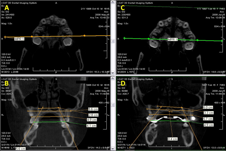
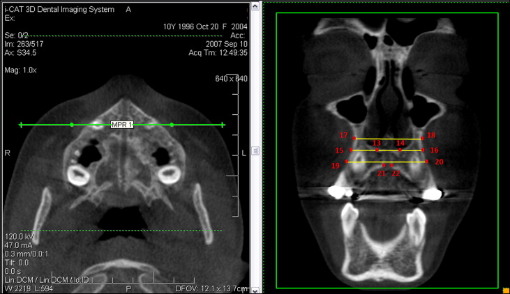
For transverse maxillary posterior region evaluation, the DICOM files with CBCT images at T1 and T2 were imported into EFILM and visualized as axial images arranged side by side. To obtain standardized axial and coronal slices and thus allow the comparisons between T1 and T2, the following references were used. In the axial slices, the images that displayed the root canal in the most apical region of the palatal root of maxillary first permanent molars were selected. By using the MultiPlanar Reformation tool, the MultiPlanar Reformation line was positioned at the root canal in the most apical region of the palatal root of the maxillary first permanent molars on the right and left sides. From these references, standardized coronal images were produced, and the measurements were made ( Fig 2 ). The landmarks used for evaluation of the maxillary posterior region are shown in Figure 3 and described in Table I .
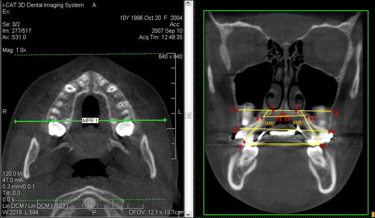
| Skeletal | ||
| Line 1-2 | Posterior baseline | Line formed by the 2 lower points at the inferior inner contour of the posterior nasal cavity on the right and left sides, respectively. |
| Line 13-14 | Anterior baseline | Line formed by the 2 lower points at the inferior inner contour of the anterior nasal cavity on the right and left sides, respectively. |
| Distance 5-6 | Posterior apical base width | Distance between points 5 and 6 (points formed by the intersection of the line 1-2 with buccal contour of maxilla on the right and left sides, respectively). |
| Distance 11-12 | Posterior midpalatal suture width | Distance between points 11 and 12 (lower points at medial limits of maxillary palatine processes, on the right and left sides, respectively), representing the midpalatal suture. |
| Distance 15-16 | Anterior apical base width (inferior) | Distance between points 15 and 16 (points formed by the intersection of line 13-14 with buccal contour of maxilla on the right and left sides, respectively). |
| Distance 17-18 | Anterior apical base width (superior) | Distance between points 17 and 18 (intersection of the straight line, which is parallel and 5 mm superior to line 13-14, with buccal contour of maxilla on the right and left sides, respectively). |
| Distance 21-22 | Anterior mid-palatal suture width | Distance between points 21 and 22 (lower points at medial limits of maxillary palatine processes, on the right and left sides, respectively), representing the midpalatal suture in the anterior region. |
| Alveolar | ||
| Distance 3-4 | Posterior width at the alveolar crest level | Distance between points 3 and 4 (coronal-most points of the maxillary buccal alveolar processes, on the right and left sides, respectively). |
| Distance 19-20 | Anterior width at midalveolar level | Distance between points 19 and 20 (intersection of the straight line, which is parallel and 5 mm inferior to line 13-14, with buccal contour of maxilla on the right and left sides, respectively). |
| Dental | ||
| Distance 7-8 | Intermolar width at occlusal surface | Distance between points 7 and 8 (points formed by the intersection of a straight line, that superimpose the long axis of the root canal of first permanent molar palatine root, with the occlusal surface on the right and left sides, respectively). |
| Distance 9-10 | Intermolar width at palatal root apices | Distance between points 9 and 10 (apices of palatine root of permanent first molars, on the right and left sides, respectively). |
| Angle 1MD | Right first molar angulation | Angle formed by the straight line from point 7 and that superimposes the long axis of the root canal of permanent first molar palatine root, on the right side, with line 1-2. |
| Angle 1ME | Left first molar angulation | Angle formed by the straight line from point 8 and that superimposes the long axis of the root canal of permanent first molar palatine root, on the left side, with the line 1-2. |
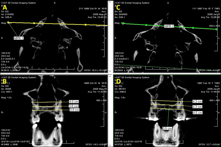
The analyses of the transversal changes in the maxillary anterior region were performed in a similar way to those of the posterior region. In the axial slices, images at T1 and T2 were selected with the root canals in the most apical region of the roots of the maxillary permanent canines visualized. After that, the MultiPlanar Reformation line was positioned at the root canal in the most apical region of the maxillary permanent canine root on the right and left sides. From theses references, standardized coronal images were produced, and the measurements were made ( Fig 4 ). The landmarks used to evaluate the RME effects in the anterior region of maxilla are shown in Figure 5 and described in Table I .
Statistical analysis
Intraexaminer reliability of the measurements was determined by intraclass correlation coefficients. Double assessments of each parameter at T1 and T2 (10 days apart) of 15 randomly selected patients from both groups were compared ( Table II ). The data obtained from all measurements were processed with SAS software (version 9.0.2, SAS, Cary, NC). Means and standard errors for each parameter were calculated, and data at T1 and T2 were compared by using the mixed analysis of variance (ANOVA) model and the Tukey-Kramer method at a significance level of 5%.
| Measurement | ICC |
|---|---|
| Distance 5-6 | 0.98 |
| Distance 11-12 | 0.94 |
| Distance 15-16 | 0.96 |
| Distance 17-18 | 0.95 |
| Distance 21-22 | 0.61 |
| Distance 3-4 | 0.98 |
| Distance 19-20 | 0.96 |
| Distance 7-8 | 0.95 |
| Distance 9-10 | 0.97 |
| Angle 1MD | 0.93 |
| Angle 1ME | 0.74 |
Results
The overall immediate effects of RME on the transverse plane are shown in Table III . There were significant increases in maxillary width at the skeletal, alveolar, and dental levels for both the Haas ( Table IV ) and the hyrax ( Table V ) groups in all parameters ( P <0.05). There was less expansion at the skeletal than at the dental level, just as the increase in the maxillary apical base was smaller in the posterior region (distances 5-6 and 11-12) compared with the anterior (distances 15-16, 21-22) ( Tables III-V ). The hyrax group had greater statistically significant increases in the maxillary transverse dimensions at the skeletal level than did the Haas group in both posterior (distances 5-6 and 11-12) and anterior (distance 21-22) regions ( Table VI ). There was no significant difference between the groups for the buccal inclination of the maxillary first permanent molars, except for the linear measure (distance 9-10), which indicated greater inclination of these teeth in the Haas group than in the hyrax group ( Table VI ).
| Variable | T1 | T2 | Change | P | |||
|---|---|---|---|---|---|---|---|
| Mean | SE | Mean | SE | Mean | SE | ||
| Skeletal | |||||||
| Distance 5-6 (mm) | |||||||
| Posterior apical base width | 60.29 | 0.64 | 62.93 | 0.64 | 2.64 | 0.11 | <0.0001 ∗ |
| Distance 11-12 (mm) | |||||||
| Posterior midpalatal suture width | 00.00 | 0.08 | 02.86 | 0.08 | 2.88 | 0.09 | <0.0001 ∗ |
| Distance 15-16 (mm) | |||||||
| Anterior apical base width (inferior) | 38.37 | 0.61 | 41.85 | 0.61 | 3.48 | 0.23 | <0.0001 ∗ |
| Distance 17-18 (mm) | |||||||
| Anterior apical base width (superior) | 38.96 | 0.83 | 41.78 | 0.83 | 2.82 | 0.23 | <0.0001 ∗ |
| Distance 21-22 (mm) | |||||||
| Anterior midpalatal suture width | 00.00 | 0.10 | 04.00 | 0.11 | 4.00 | 0.13 | <0.0001 ∗ |
| Alveolar | |||||||
| Distance 3-4 (mm) | |||||||
| Posterior width at alveolar crest level | 51.65 | 0.51 | 57.28 | 0.51 | 5.63 | 0.16 | <0.0001 ∗ |
| Distance 19-20 (mm) | |||||||
| Anterior width at midalveolar level | 40.06 | 0.58 | 44.46 | 0.58 | 4.40 | 0.22 | <0.0001 ∗ |
| Dental | |||||||
| Distance 7-8 (mm) | |||||||
| Intermolar width at occlusal surface | 43.51 | 0.44 | 51.31 | 0.44 | 7.80 | 0.15 | <0.0001 ∗ |
| Distance 9-10 (mm) | |||||||
| Intermolar width at palatal root apices | 29.90 | 0.52 | 32.55 | 0.52 | 2.65 | 0.14 | <0.0001 ∗ |
| Angle 1MD (°) | |||||||
| Right first molar angulation | 110.6 | 1.4 | 118.1 | 1.4 | 7.53 | 0.74 | <0.0001 ∗ |
| Angle 1ME (°) | |||||||
| Left first molar angulation | 117.7 | 1.2 | 123.8 | 1.2 | 6.17 | 0.68 | <0.0001 ∗ |
| Variable | T1 | T2 | Change | P | |||
|---|---|---|---|---|---|---|---|
| Mean (mm) | SE (mm) | Mean (mm) | SE (mm) | Mean (mm) | SE (mm) | ||
| Skeletal | |||||||
| Distance 5-6 | |||||||
| Posterior apical base width | 61.10 | 0.87 | 63.29 | 0.87 | 2.19 | 0.15 | <0.0001 ∗ |
| Distance 11-12 | |||||||
| Posterior midpalatal suture width | 00.00 | 0.11 | 02.61 | 0.11 | 2.62 | 0.12 | <0.0001 ∗ |
| Distance 15-16 | |||||||
| Anterior apical base width (inferior) | 38.98 | 0.82 | 42.28 | 0.82 | 3.29 | 0.30 | <0.0001 ∗ |
| Distance 17-18 | |||||||
| Anterior apical base width (superior) | 39.70 | 1.12 | 42.33 | 1.12 | 2.62 | 0.31 | <0.0001 ∗ |
| Distance 21-22 | |||||||
| Anterior midpalatal suture width | 00.00 | 0.15 | 03.63 | 0.15 | 3.63 | 0.17 | <0.0001 ∗ |
| Alveolar | |||||||
| Distance 3-4 | |||||||
| Posterior width at alveolar crest level | 51.96 | 0.69 | 57.41 | 0.69 | 5.44 | 0.25 | <0.0001 ∗ |
| Distance 19-20 | |||||||
| Anterior width at midalveolar level | 40.56 | 0.79 | 44.59 | 0.79 | 4.03 | 0.30 | <0.0001 ∗ |
| Dental | |||||||
| Distance 7-8 | |||||||
| Intermolar width at occlusal surface | 43.42 | 0.59 | 51.12 | 0.59 | 7.70 | 0.20 | <0.0001 ∗ |
| Distance 9-10 | |||||||
| Intermolar width at palatal root apices | 30.57 | 0.71 | 32.72 | 0.71 | 2.15 | 0.18 | <0.0001 ∗ |
Stay updated, free dental videos. Join our Telegram channel
VIDEdental - Online dental courses


