Introduction
The purpose of this study was to use photoelastic analysis to compare the system of forces generated by retraction T-loop springs made with stainless steel and titanium-molybdenum alloy (TMA) (Ormco, Glendora, Calif) with photoelastic analysis.
Methods
Three photoelastic models were used to evaluate retraction T-loop springs with the same preactivations in 2 groups. In group 1, the loop was constructed with a stainless steel wire, and 2 helicoids were incorporated on top of the T-loop; in group 2, it was made with TMA and no helicoids.
Results
Upon using the qualitative analysis of the fringe order in the photoelastic model, it was observed that the magnitude of force generated by the springs in group 1 was significantly higher than that in group 2. However, both had symmetry for the active and reactive units related to the system of force.
Conclusions
Both springs had the same mechanical characteristics. TMA springs showed lower force levels.
Orthodontists have used many devices to close the remaining spaces after tooth extractions. One of them is the T-loop spring suggested by Burstone in 1982. Among its advantages, the low load-deflection ratio (L/D) is significant. Because of the shape of the spring, which incorporates much wire in its form, and with 0.017 × 0.025-in titanium-molybdenum alloy (TMA) wire, it is possible to work with a greater activation for a longer time and a relatively low force, when compared with other springs with high L/D.
The moment-to-force ratio (M/F) established by the T-loop spring relating to the center of resistance of the tooth and the force can be changed by the orthodontist, according to the preactivated bends. This results in better control of the axial movement and makes it possible to select different types of movements.
The force system generated by the T-loop spring is controlled by the integration of the preactivated bends, the activation amount, and the position of the spring in the interbracket distance. Hoenigl et al evaluated a centralized T-loop force system by first activating it at the maximum level and then deactivating it gradually until it reached the lowest level of deactivation. They concluded that the force system generated by this type of spring provides movements from a controlled crown tip-back to a radicular correction.
The efficiency of this type of spring was already shown by clinical evidence, and its power system was evaluated by mechanical testing and software. Photoelastic analysis is a widely used optical technique for examining and measuring stress distribution in structures exposed to internal or external forces. In this technique, polarized light is transmitted through a photoelastic active material, which is doubly refractive when stressed. When the emergent light waves are viewed through an analyzer filter, the stress patterns appear as fringes or bands of color.
In dentistry, photoelasticity was introduced by Zak in 1935 during the study in which he assessed the type of tooth movement, strength, and point of application of the forces. In orthodontics, this technique has been used to examine the stresses induced during canine retraction with other devices that do not use a T-loop spring and with lingual appliances to evaluate stresses created by occlusal forces in the periodontal tissues and those produced by orthopedic forces.
Based on the above-mentioned findings, in this study we focused on objective evaluation through qualitative analysis in a photoelastic model of the force systems generated by the centralized T-loop made with stainless steel (SS) and TMA (Ormco, Glendora, Calif) wires, both 0.017 × 0.025 in.
Material and methods
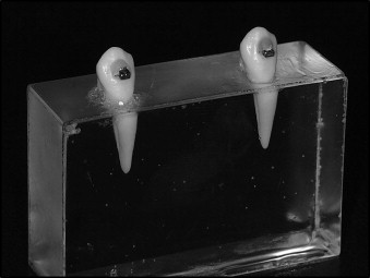
The photoelastic model was prepared by positioning the 2 teeth separated by a distance of 27 mm ( Fig 1 ). Once the models were constructed, crisscross tubes were placed on the crowns by using a cylindrical drill at low rotation, and a vertical slot was made where the tubes were placed with acrylic resin.
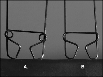
To obtain high confidence of the results, 2 groups of T-loops were built, and the tests were repeated thrice. For the first group, 3 springs were made of SS wire including helicoids to reduce the L/D ratio ( Fig 2 , A ). For the second group, the springs were made of 0.017 × 0.025-in TMA wire ( Fig 2 , B ) with no helicoids (Ormco). All T-loop springs were made with a template of 10-mm length and 7-mm height. Preactivation bends were incorporated on all springs. On the apical base, the angle was of 45°, and, on its horizontal extension, the bends were made symmetrically, totaling 187°.
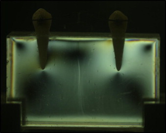
After checking them in a neutral position, the springs were placed in the horizontal slot of the tubes, centralized at a 27-mm distance. The T-loops were then evaluated in 3 activations: 5, 2.5, and 0 mm (neutral position).
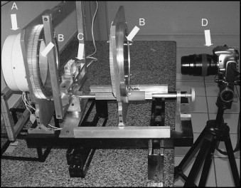
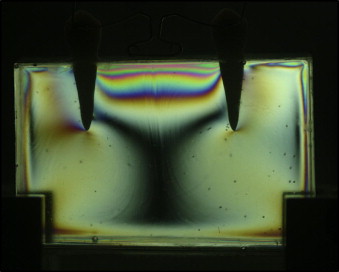
The tests were performed by using a circular polariscope ( Fig 3 ), which comprised a light system ( Fig 3 , A ), 2 polarizers ( Fig 3 , B ), a support to handle the photoelastic model ( Fig 3 , C ), and a digital camera to record the results ( Fig 3 , D ).
After activating the T-loop, the fringe order in the radicular surface was read through the interface of 2 colors, violet and blue, in the distal, mesial, and apical areas of each tooth. This fringe order was displayed in graphs for each surface: mesial, distal, and apical.
Results and discussion
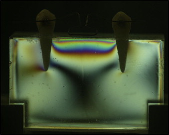
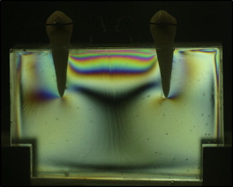
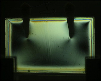
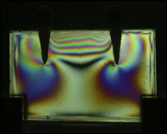
In this study, we intended to evaluate comparatively the force systems generated by centralized T-loop springs made of SS and TMA wires (0.017 × 0.025 in) in 3 activations (0, 2.5, and 5 mm), shown in Figures 4 , 5 , and 6 , respectively. To obtain similar L/D ratios of the 2 T-loop springs tested, helicoids were incorporated to the SS T-loop spring design, shown in Figures 7 , 8 , and 9 . The preactivation protocols were equal for both TMA and SS springs.
The photoelastic model was chosen for this purpose instead of the finite element method, because the fringes spontaneously generated during the photoelastic test express the forces released by each spring configuration in the 3 activations. These fringes also afford a means of visualizing and analyzing the forces exerted at the various areas of root surfaces. The finite element method is a kind of computer-aided test simulation that can show the force systems generated by the T-loop springs, based on the records placed on the software used for this objective. In this study, although the T-loop springs were made of different alloys, theoretically, the force system of the 2 T-loop springs tested should be the same; thus, similar records would be introduced in the software used with the finite element method analysis, and this situation would show similar force releases instead of identifying any possible differences according to the type of T-loop spring tested.
According to the results of this study, this photoelastic model showed similar force systems in both sides.
The interpretations were descriptive; the readings were made through graphics, with each graphic representing a mesial, apical, or distal portion, separately analyzed.
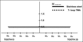
To standardize it and have the data readings more understandable, the following nomenclature was used: 13, left tooth to the observer; 23, right tooth to the observer; A, apical area to the observer; M, mesial area to the observer; and D, distal area to the observer.
The photoelastic model was observed to be free of tension. In this case, the fringe order of 0.0 in all root surfaces for both teeth in the A, M, and D areas was coincidently at zero point.
The SS T-loop generated a symmetric force system in all root surfaces. The fringe orders in the mesial ( Fig 10 ) and apical ( Fig 11 ) areas were close to 0.5, providing a higher amount of energy when compared with the TMA T-loop. It was observed that the amount of stress generated by the SS T-loop with helicoids extended to the center of the model resulting in a fringe order of 0.5, a phenomenon not observed in the same area of the model with the TMA T-loop, in which the fringe order was 0.0. In the distal surface of the SS T-loop, the fringe order was close to 0.0, which was lower than the fringe order observed with the TMA spring ( Fig 12 ).