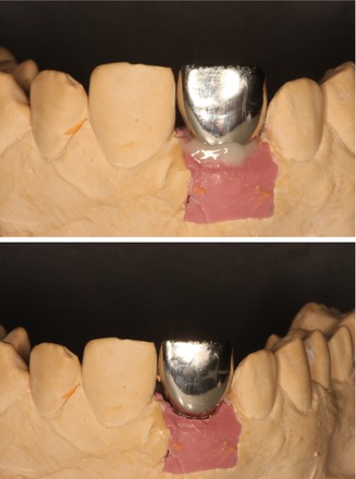
Fig. 6.1
Cast model with implant analogue and artificial soft tissue
Palatal openings were made in the crowns in order to have access to the abutment screw after cementation. This was necessary to ensure the retrievability of abutment/restoration system. The abutments were modeled with various positions of the margin for the restorations, consisting of five groups of five specimens (Fig. 6.2):
Fig. 6.2
Individually casted prosthetic abutments with different location of cementation margins
-
Group 1 (control) at 1 mm above the gingival level
-
Group 2 at the soft tissue margin
-
Group 3 at 1 mm below the marginal level
-
Group 4 at 2 mm below the gingival level
-
Group 5 at 3 mm subgingivally
Resin-modified glass ionomer cement Fuji PLUS (GC, Tokyo, Japan) was selected as a luting agent in this study. Before cementation, the top of each prosthetic abutment was covered using dental wax to protect the abutment screw. The palatal openings were closed with composite material to obturate the screw access space and prevent venting of luting agent during cementation. After setting, the excess was removed with a stainless steel explorer and super-floss until the researcher decided it had been completely cleaned (Figs. 6.3 and 6. 4). Then, the composite and wax were removed, the abutment screw was unscrewed, and the suprastructure was dismounted for assessment (Fig. 6.5).
Figs. 6.3 and 6.4
Cement excess after cementation and cleaning of the crown
Fig. 6.5
Removal of the restoration through palatal side
Two techniques were selected to evaluate the excess of cement left after cleaning: the computerized planimetric method of cement assessment and weighing. First, all four quadrants (mesial, distal, labial, and lingual) of the specimens were photographed using a specially constructed device to keep the standardized distance between the photo camera and the specimen. The images were imported and analyzed using Adobe Photoshop (Adobe Systems Ltd, Europe, Uxbridge, UK). Each surface area of the specimen was measured manually with the drawing facility to outline the boundaries of each quadrant. The total surface area was marked and the number of pixels was recorded from the histogram option, the same was applied to the area covered with cement remnants (Fig. 6.6). The ratio between the area covered with cement and the total surface area of the specimen was calculated. Results have shown that the increase of cement remnants in weight (P = 0.001) and proportion (P = 0.001) as the restoration margins were located deeper subgingivally (Kruskal–Wallis test, P ≤ 0.05). Statistically significant differences were registered between all the groups (P ≤ 0.05), except groups 4 and 5 (P ≥ 0.05), when the cement excess weight was evaluated. Assessment of proportion showed statistically significant differences between all the groups (P ≤ 0.05), except groups 1 and 2 and groups 4 and 5 (P ≥ 0.05) (Figs. 6.7 and 6.8). Spearman’s correlation coefficient showed significant relation between both measuring techniques (r = 0.889; P = 0.001). This means that pixel calculation is as reliable as actual weighting of the cement remnants; therefore, this method can be used also clinically.
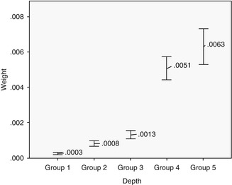
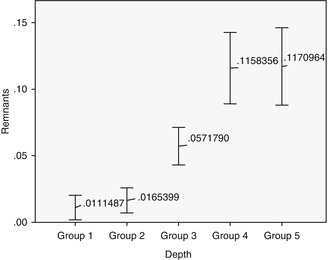
Fig. 6.6
Cement remnants around abutments/crowns in different depth. Note the increase of cement as the depth of restorative margin goes deeper
Fig. 6.7
Differences between groups in weighting
Fig. 6.8
Differences in groups in pixels
In summary, it can be concluded that it is difficult to remove all cement excess after cementation if the margins are located subgingivally. The deeper the position of the margin, the greater the amount of cement can be undetected, while all cement remnants were removed only when the margin was visible. The greatest amount of cement remnants was left when the crown margin was 2 or 3 mm below the gingival level. This seems to be a logical outcome as the finish line was clearly visible and the investigator could remove the excess without difficulties. Of course, the results of laboratory study cannot be transferred directly to the clinical practice, as in vitro experiments lack essential intraoral conditions, like saliva, gingival pressure, etc. Therefore, results of in vitro study have to be tested by clinical trials if the issue is to be clinically valid.
Prospective Clinical Study
A prospective clinical study was performed to find out whether results of in vitro study could be validated by clinical trial. Sixty-five internal hexagon implants (BioHorizons Internal, Birmingham, AL, USA) were installed in 65 patients, 35 in the maxilla and 30 in the Mandibular jaw. After healing, 65 single metal-ceramic crowns with occlusal openings were fabricated. Standard prosthetic abutments were selected to support the restorations because it was important to have the same distance to cementation shoulder according to the implant. In addition, we wanted to simulate usual clinical work, as standard abutments were casually used at that time. Evaluation of the implant depth mesially, distally, lingually, and buccally was performed as the position of the cementation margin in case a standard abutment is used that varies in respect to all sites of the implant (Fig. 6.9). The data were divided into four groups according to the depth of the margin position: group 1 at the soft tissue margin, group 2 at 1 mm subgingivally, group 3 at 2 mm below marginal level, and group 4 at 3 mm subgingivally. The cementation and remnants evaluation techiques were very similar to the described preceding in vitro study. The occlusal openings of the crowns were closed with composite to prevent venting of luting agent during cementation. Resin-modified glass ionomer cement was mixed according to the manufacturer’s instructions, taking the same ratio (1 little scoop of powder and 1 drop of liquid, as recommended by manufacturer) for each crown. A thin layer was applied to all the internal surfaces of the crowns and seated onto the abutment with a gentle finger pressure (Fig. 6.10). When setting the cement reached a rubbery consistency, the excess was removed using a stainless steel explorer, dental floss and super-floss until the researcher decided it had been completely cleaned. Then, radiographic images were made using a paralleling technique with a Rinn-like film holder in high-resolution mode. If residual cement was detected on a radiograph, cleaning procedures were repeated until a radiographic evaluation showed no cement remnants. Then the composite and wax were removed, the abutment screw was unscrewed, and the suprastructure was dismounted for assessment.
Fig. 6.9
Different depth of the cementation margin in standard abutment in respect to soft tissues
Fig. 6.10
Measurements of implant depth in four quadrants
After the removal of the restoration, a photograph of the implant and surrounding tissues was made perpendicularly, using an intraoral occlusal dental mirror for evaluation of cement remnants in the tissues (Fig. 6.11). Various amounts of cement remnants were located on all retrieved superstructures and in peri-implant tissues of restored implants. Kruskal–Wallis test showed statistically significant increase of excess cement quantity on the abutment/restoration complex, as the restoration margins were located deeper subgingivally (P = 0.001). There was a significant dependence of cement remnant amount in the peri-implant sulcus and location of the margin (P = 0.0045). During the first radiographic evaluation, cement remnants mesially were visible in 7.5 % and in 11.3 % of all cases (Fig. 6.12).
Fig. 6.11
Cementation of the restoration. Note the composite on the occlusal surface to prevent the venting of the cement
Fig. 6.12
Measurement of cement remnants in the soft peri-implant tissues after cleaning
The main finding of the study was that despite careful cleaning, various amounts of cement remnants were present on the abutment/restoration complex and in the peri-implant sulcus. The deeper the position of the margin was located, the more undetected cement particles were found after the removal of the restoration. It is interesting to note that in all cases, when cement remnants were not cleaned, the researcher was sure that it was removed. It shows that false convictions of the clinician may contribute to the results we had. This was also registered in previous in vitro studies. Common use of standard abutments for intraoral cementation and contradicting information in the literature might be the reasons due to the misguided belief that cement removal is very easy and posses no difficulties. The properties of dental cement may also have had influence on the results of this clinical trial. Almost two decades ago, Agar et al. showed that dental cement containing resins was the most difficult to remove from the surface of abutments. In addition, the removal of such cement resulted in the most extensive scratching of the metal surface.
Likewise, a recent survey has shown that glass ionomer modified with resins is the most popular cement to use for permanent delivery of implant-supported restorations in US dental schools, reaching up to 70 % of usage. This clinical study could suggest the recommendation that clinicians should select cement with less adhesive characteristics for cementation of implant restorations, like zinc phosphate, whose cleaning properties are much superior to other cements. One of the factors to explain this phenomenon probably lies in the process of conventional cementing restorations on teeth. During seating, hydraulic pressure builds up and cement travels to the direction of least resistance, through the margin to the gingival sulcus. However, the perpendicular fiber attachment around teeth provides a sufficient barrier, and cement excess does not penetrate further and escapes to the surface of the gingival sulcus, where it is more readily detected. It is well known that peri-implant tissues do not possess similar protective mechanisms and are less resistant to pressure. Thus, cement excess may be pushed further subgingivally with only a part of it escaping to the surface. In contrast to teeth, the peri-implant tissues lack resistance to pressure due to the absence of an attachment to the implant surface. Connective tissue fibers do not attach to the implant and align themselves parallel along the fixture surface. Subsequently, the peri-implant tissues may be less resistant to pressure compared with tissues around teeth. Several studies have shown that pressure ranging from 20 to 130 N can be developed during the cementation of crowns. This would suggest that cement may be pushed deeper in the peri-implant sulcus and defy removal even after meticulous attempts at cleaning.
Validity of Radiographic Evaluation
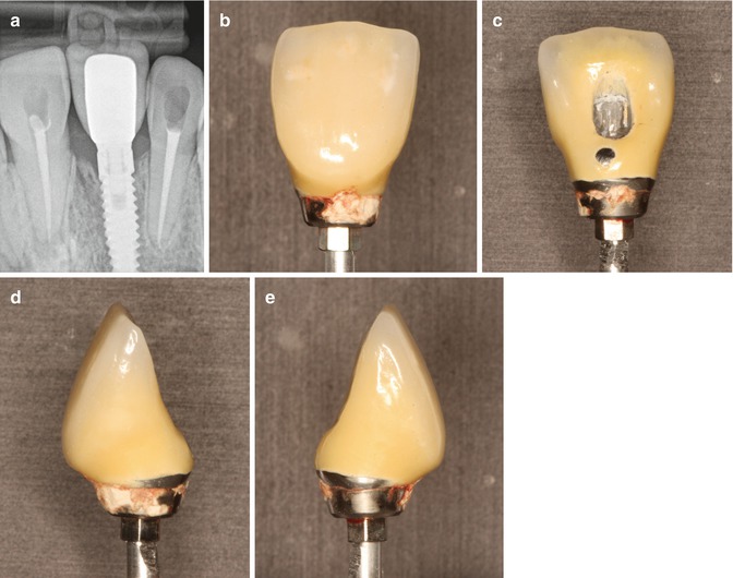
The most interesting finding was that radiographic examination could not be trusted to detect pieces of cement. It is obvious that it is impossible to inspect the palatine/lingual and facial areas due to the obstruction of the implant/abutment complex. Traditionally, proximal areas are considered the mostly likely place where cement extrusion can be easily detected, although usually the soft tissues are thicker here due to the presence of papillae. However, results of this clinical study have shown that this is not necessarily the case. Cement remnants were visible medially only in two cases and in five cases distally out of 35 radiographic images, 5.7 and 14.3 %, respectively. A partial explanation to that may be found in the study by Wadhwani et al., which has proved that radiographic density of implant restorative cements is rather poor and greatly depends on the thickness of the specimens. For example, resin-reinforced glass ionomer used in this study could be detected only when cement thickness of 2 mm was irradiated. This means that smaller particles of excess cement are not visible even proximally, where no blocking of the implant body exists. In addition, very frequently, however, because the cement tends to flow circumferentially around implant restorations, there are occasions when even thin layers can be detected radiographically. Provided the clinician understands this phenomenon, known as the peripheral egg shell effect (see chapter 5). This increases the observed radiographic effect as the thin circumferetial layer attenuates the x-ray beam at a tangent-making it more likley to be seen (Fig. 6.13a–e).
Stay updated, free dental videos. Join our Telegram channel
VIDEdental - Online dental courses


