Introduction
The objective of this research was to compare the effect of preactivation on the force system of beta-titanium T-loop springs (TLSs).
Methods
Twenty TLSs with dimensions of 6 × 10 mm, of 0.017 × 0.025-in beta-titanium alloy, were randomly divided into 2 groups according to their preactivation. By using a moment transducer coupled to a digital extensometer indicator adapted to a testing machine, the amounts of horizontal force and moment produced were recorded at every 0.5 mm of deactivation from 5 mm of the initial activation in an interbracket distance of 23 mm. The moment-to-force ratio, the “neutral position” and the load-deflection ratio were also calculated.
Results
TLSs preactivated by curvature delivered horizontal forces significantly lower than those preactivated by concentrated bends. No differences were found in relation to the moments produced throughout the deactivation of both groups. The moment-to-force ratios were systematically higher on the TLSs preactivated by curvature than those preactivated by concentrated bends, except on 5 mm of activation. Significant differences were found in the load-deflection rates and “neutral position.”
Conclusions
The TLSs preactivated by curvature delivered lower horizontal forces and higher moment-to-force and load-deflection ratios than did those preactivated by concentrated bends.
The mechanics in orthodontics for reciprocal space closure can be accomplished in 2 ways, by either sliding or frictionless mechanics. In frictionless mechanics, several kinds of vertical loops can be used for space closure, including the bull loop, teardrop loop, and T-loop. The T-loop spring (TLS) takes advantage of an excessive amount of wire added apically to itself, which gives this specific design several advantages. They include a lower load-deflection (LD) ratio than other vertical loops, such as bull loops, which can be further improved with beta-titanium alloy instead of stainless steel, allowing a greater span of activation. This design also produces a higher moment of activation at the same height compared with other loops.
Even though a high moment of activation can be produced, it might not be enough to produce translation, and the moment produced needs to be further increased by the addition of a residual moment—ie, by increasing the angulations of the extremities of the loops, in a procedure known as preactivation. Most other parameters of the beta-titanium alloy TLS have been widely researched, including spring height, displacement of the spring within the interbracket distance, amount and type of preactivation, horizontal activation, and alloy, which can all alter the moment-to-force (MF) ratio delivered to the teeth. Although these parameters are well established, the effects of different types of preactivation are not completely understood. More specifically, differences between TLS preactivated by a curvature vs concentrated bends have not yet been systematically studied.
Only 2 studies have made comparisons between those 2 kinds of preactivations. One of them, however, was not designed to compare curvature and bends, but the effect of wire size on the force system. Moreover, the angulations between both anterior and posterior extremities of the loops they used were different, as seen by the templates depicted in their materials section; this could confound their results. The other report used computer simulations produced by loop-simulation analysis software; the predictions were similar to the experimental values but could be different from the clinical reality. This can occur because of errors of the computer simulation that are mainly due to various simplifications of the theoretical method applied. These simplifications are deemed necessary, either to produce results in a reasonable time period or because our current knowledge of materials does not allow modelling adequately such complex phenomena as strain hardening, plastic deformation, and crystal imperfections, all of which occur in a mechanical setup.
Because of the lack of mechanical reports describing the influence of those 2 kinds of preactivations, the purpose of this study was to mechanically compare the force systems of symmetrical TLSs preactivated by either curvature or concentrated bends.
Material and methods
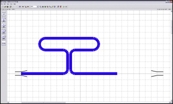
Twenty TLSs were hand-bent by an author (S.G.F.R.C.) using a Marcotte pliers (Hu-Friedy, Chicago, Ill) made of 0.017 × 0.025-in beta-titanium alloy (TMA; Ormco, Glendora, Calif) wires, according to a custom-made template ( Fig 1 ). The TLSs had dimensions of 6 mm in height by 10 mm of length, and were randomly divided into 2 groups according to what preactivation was going to be used, curvature or concentrated bends.
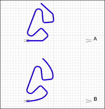
The preactivations were added to the TLSs with templates that were previously designed ( Fig 2 ), where the loops had the same angulation between their horizontal extremities. The TLSs were supposed to follow within the template after trial activation, used for the stress relief.
A universal testing machine (EMIC, São José dos Pinhais, Brazil), equipped with a load cell of 0.1 kN, was coupled to a moment transducer and a digital extensometer indicator (Transdutec, São Paulo, Brazil) for the tests. The speed used for the test was 5 mm per minute, and the digital extensometer’s excitation and sensitivity were 5 V and 0.5 mV/V, respectively.
Since the TLSs were supposed to be positioned symmetrically for the test in an interbracket distance of 23 mm and activated by 5 mm, the following formula was used to calculate the amount of wire before and after the loop: interbracket distance – activation divided by 2.
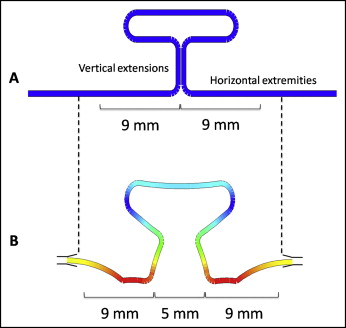
Nine millimeters were measured from the center of the loop toward each extremity of the horizontal extremities, where stops were made ( Fig 3 ). This procedure also ensured the correct horizontal activation and the centralization of the TLSs.
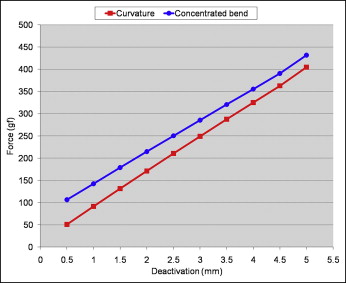
After the initial activation, the horizontal forces and moments produced were recorded for every 0.5 mm of deactivation, and MF ratios were calculated. Furthermore, the amount of overlap of the vertical extensions of the TLS in “neutral position” (deformation assumed by a spring when its extremities are placed parallel to the positions where they will be fitted on the patient’s brackets, not producing any force, only moments) was calculated by linear interpolation. The LD ratio (slope of the deactivation graph) was also obtained based on the graph ( Fig 4 ).
SPSS software (version 16.0; SPSS, Chicago, Ill) was used for the statistical analysis with the groups blinded from the test operator (S.G.F.R.C.). The Kolmogorov-Smirnov test indicated a normal distribution of the data, and the Levene test showed that all variables had similar variances, so a t test at a significance level of 5% was used to compare the groups’ differences.
Results
The TLSs preactivated by curvature produced horizontal forces significantly lower (404.7-50.7 gf between 5 and 0.5 mm of deactivation) than did the TLSs preactivated by concentrated bends (431.5-106.4 gf) throughout the whole deactivation process ( Table , Fig 4 ). However, the LD ratio for the curvature group was higher (78.1 gf/mm) than for the concentrated bends group (71.7 gf/mm) ( P <0.001).
| Distance (mm) | Curvature preactivation | Concentrated bend preactivation | Group differences P value | |||
|---|---|---|---|---|---|---|
| Mean | SD | Mean | SD | |||
| Force | 5.0 | 404.7 | 27.0 | 431.5 | 23.1 | 0.028 ∗ |
| 4.5 | 362.7 | 25.9 | 390.6 | 21.3 | 0.017 ∗ | |
| 4.0 | 325.2 | 25.4 | 355.4 | 21.0 | 0.01 ∗ | |
| 3.5 | 287.4 | 24.8 | 320.6 | 20.9 | 0.005 ∗ | |
| 3.0 | 249.0 | 24.4 | 285.5 | 20.7 | 0.002 ∗ | |
| 2.5 | 210.4 | 24.1 | 250.3 | 20.6 | 0.001 ∗ | |
| 2.0 | 171.2 | 23.8 | 214.7 | 20.8 | <0.001 ∗ | |
| 1.5 | 131.5 | 23.7 | 178.6 | 21.0 | <0.001 ∗ | |
| 1.0 | 91.3 | 23.7 | 142.5 | 21.5 | <0.001 ∗ | |
| 0.5 | 50.7 | 23.9 | 106.4 | 22.0 | <0.001 | |
| Neutral position | −0.18 | 0.3 | −0.99 | 0.3 | <0.001 ∗ | |
| LD | 78.1 | 3.8 | 71.7 | 3.2 | <0.001 ∗ | |
| Moment | 5.0 | 2303.0 | 172.3 | 2301.2 | 124.4 | 0.979 |
| 4.5 | 2222.6 | 165.8 | 2218.3 | 122.1 | 0.948 | |
| 4.0 | 2143.1 | 157.6 | 2137.8 | 113.8 | 0.932 | |
| 3.5 | 2061.6 | 153.3 | 2056.5 | 108.2 | 0.933 | |
| 3.0 | 1982.7 | 145.8 | 1974.9 | 104.5 | 0.893 | |
| 2.5 | 1900.8 | 141.2 | 1889.4 | 104.3 | 0.839 | |
| 2.0 | 1819.1 | 136.7 | 1811.0 | 102.4 | 0.882 | |
| 1.5 | 1742.8 | 136.5 | 1730.0 | 104.0 | 0.817 | |
| 1.0 | 1662.3 | 137.1 | 1646.8 | 107.7 | 0.782 | |
| 0.5 | 1572.3 | 140.8 | 1559.8 | 113.0 | 0.829 | |
| MF | 5.0 | 5.7 | 0.5 | 5.4 | 0.4 | 0.079 |
| 4.5 | 6.1 | 0.5 | 5.7 | 0.4 | 0.047 ∗ | |
| 4.0 | 6.6 | 0.6 | 6.0 | 0.5 | 0.02 ∗ | |
| 3.5 | 7.2 | 0.6 | 6.4 | 0.5 | 0.007 ∗ | |
| 3.0 | 8.0 | 0.7 | 7.0 | 0.6 | 0.002 ∗ | |
| 2.5 | 9.1 | 0.9 | 7.6 | 0.7 | <0.001 ∗ | |
| 2.0 | 10.8 | 1.2 | 8.5 | 0.9 | <0.001 ∗ | |
| 1.5 | 13.6 | 2.0 | 9.8 | 1.2 | <0.001 ∗ | |
| 1.0 | 19.2 | 4.5 | 11.8 | 1.8 | <0.001 ∗ | |
| 0.5 | 41.1 | 27.2 | 15.2 | 3.1 | <0.001 ∗ | |
Stay updated, free dental videos. Join our Telegram channel
VIDEdental - Online dental courses


