(1)
Canberra, ACT, Australia
Summary
Endodontics, since its inception, has resulted in numerous concepts, strategies and techniques for preparing canals. Over the decades, a staggering array of files has emerged for negotiating and shaping canals principally based on either stainless steel or nickel–titanium alloys. Manufacturers are constantly developing file systems intended to improve on previous generations with proven performance features based on past and recent technological advancement. The clinician must be able to justify the use of these systems based on scientifically proven evidence-based research and clinical outcomes. Changing instrumentation techniques, particularly if it is a radical departure from your usual technique, will require attendance on hands-on courses and vigorous laboratory testing, preferably on extracted teeth, followed by integration into daily practice following careful case selection.
Clinical Relevance
The mechanical objectives of canal shaping are a means to ensure that our biologically aimed chemical preparation of canals is fulfilled. Traditional techniques included the use of a combination of a large number of stainless steel files and Gates–Glidden burs, which were prone to iatrogenic mishaps, particularly in curved canals. Since the inception of nickel–titanium alloy and its proven benefits, manufacturers have developed numerous file systems with inherent advantages and disadvantages depending on individual design features. The clinician should be aware of these features and be able to select a scientifically and clinically proven system that ensures predictable preparation with efficiency, simplicity and safety in mind.
9.1 Overview of Endodontic Instruments
Modern endodontics encompasses a multitude of technologies that have allowed us to predictably treat and prevent apical periodontitis, no more so than the advent of the nickel–titanium revolution. Yet despite this, some clinicians still fail to understand the underlying principles of tooth isolation, vision and irrigation, which together allow us to successfully and effectively debride those areas of untouched root canal anatomy that our technologically advanced instruments fail to reach. Endodontic armamentaria are constantly evolving with newer instruments and materials frequently marketed with the promise of improving and simplifying a technique and shortening the time taken and even claims of superiority over existing products. Often these promises are not fulfilled with many practitioners quickly discarding these instruments resigned to the back of a store cupboard collecting dust. Recently, the introduction of single-file systems aimed at predictably shortening the time taken to shape the canal system only serves to increase our chances of failure when negating the principles fundamental to endodontics. The astute clinician will always have in his mind’s eye that the use of the multitude of endodontic armamentaria available today is but one extension of the principles necessary to predictably clean and shape the complexities of the canal systems, allowing our patients the desired outcome we seek to achieve.
In June 1976, the Council on Dental Materials and Devices of the American Dental Association approved specification #28 [1], which established the International Standards Organization (ISO) [2–4] classification, requisite physical properties and procedures used for investigation, sampling tests and preparation of root canal files and reamers. In 1981, the specifications were revised, including requirements for a uniform file taper of 0.02 mm per mm and a tolerance of + −0.02 mm at each diameter inspection point [5]. Later, in 1989, a second revision was made on the design of cutting blades, the geometry and the angle of the tip [6].
This standardisation provided a coloured numbering system that indicated the diameter of the tip of the instrument at the first rake angle. The coloured numbering is repeated every six instruments with the exception of the first three in the series (files 06, 08 and 10). This diameter at the tip is termed D1, and the diameter at the end of the cutting edge is termed D16. The difference of the diameters D1 and D16 is always a constant 0.32 mm. This allowed for a consistent taper to instruments of whatever size (e.g. taper 0.02 means the increment in diameter is 0.02 mm × each millimetre of length). The L1/L16 distance is also constant (16 mm), so that the working portion of the instruments is always the same, despite the variability of the lengths of the available instruments (21 mm short, 25 mm long and 31 mm extra long). The obturating materials were also standardised, so that the manufacturers produce gutta-percha cones and paper points whose size and taper corresponded to those of the instruments [7, 8] (Fig. 9.1).
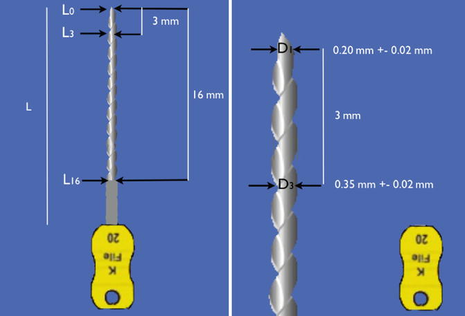
Fig. 9.1
Standardised 2 % endodontic K-file instrument. Note the diameter ‘D1’ is the diameter at the tip of the instrument to the nearest 100 hundredths of a millimetre. The diameter at the end of the cutting edge is D16. The difference between D1 and D16 is 0.32 mm conferring a consistent taper to instruments of whatever size tip (taper. 02: the increment in diameter is 0.02 mm × each millimetre in length)
Despite attempts at developing standard specifications, wide variations exist between the diameters of instruments of the same nominal size within or between different manufacturers. The tolerance limit of + −0.02 mm for all diameters has been identified as part of the problem [9, 10].
A number of endodontic files are commonly used for cleaning and shaping the root canal system. They can be manufactured from either stainless steel or nickel–titanium of either constant or variable tapers depending on the file type. Traditional standardised preparation techniques employed either reamers or files, which are effective in both a linear filing motion and rotational. Hedstroem files (H files) should only be used in a linear filing motion [11].
The use of stainless steel files in curved canals proved to be unpredictable with an increased risk of iatrogenic damage and canal transportation (zipping and ledging) which occurs in the apical 1/3 of the canal due to their inherent inflexibility [12].
To overcome the inherent problems associated with inflexible stainless steel files and difficulties negotiating tightly curved, fine canals, the use of intermediate sizes (12.5, 17.5, 22.5, etc.) has also been proposed (K-FlexoFiles Golden Mediums) [13].
Modifications to the tip design of stainless steel files have been marketed creating a rounded tip that does not cut into the canal wall. The Flex-R file designed by Roane (1985) was the first to use a non-cutting tip to help avoid ledge formation in curved canals. This design incorporated a guiding plane and removed the transition angles inherent on the tip of standard K-type files. Lacking a sharp transition angle, the Flex-R files will follow the canal, and they are prevented from gouging into the walls. The tip design causes a Flex-R file to hug the inside of a curve and prevent the tip from engaging the external wall of the curve. Other tip modifications include the use of pyramidal file tips (such as the Flex-O files) [14, 15].
C+ Files (Dentsply/Maillefer, Johnson City, TN) modified with a pyramid-shaped tip facilitates insertion during negotiation and an overall square cross section providing better resistance to distortion and less buckling compared to conventional K-files. These files allow easier location of the canal orifices and easier access to the apical third of the canal useful when negotiating fine calcified canals [16].
The application of nickel–titanium in endodontics was first reported in 1988, and since its introduction there has been a growing shift from manual hand instrumentation to rotary engine-driven preparation. They have proven to be highly flexible and elastic, reducing iatrogenic instrument complications associated with the inherent stiffness of stainless steel files. Instrument design has changed considerably with progress being made in the manufacturing process as well as alloy processing. Nevertheless, all systems have their own set of advantages and weaknesses according to the type of alloy used, degree of taper and cross-sectional design features [17–20] (Table 9.1).
Table 9.1
Design features of first- to fifth-generation rotary Ni–Ti file systems
|
Instrument system
|
Cross-sectional design
|
Taper
|
|---|---|---|
|
1st generation
|
||
|
Profile
Dentsply,
Maillefer
|
Triple U shape with radial lands
|
Fixed 2, 4 and 6 %
|
|
LightSpeed
LightSpeed, San Antonio, TX
|
Triple U shape with radial lands
Files have short cutting portion
|
Specific instrument sequences
|
|
GT Files
|
Triple U shape with radial lands
|
Fixed 4, 6, 8, 10 and 12 %
|
|
2nd generation
|
||
|
ProTaper
Dentsply, Maillefer
|
Convex triangular shape, sharp cutting edges with no radial lands
F3, F4 and F5 U flutes increase flexibility
|
Variable taper along length of instrument
|
|
K3
Sybron Endo
|
Positive rake angle for cutting efficiency
Three radial lands
Peripheral blade relief
|
Fixed 2, 4 and 6 %
|
|
RaCe
FKG, LaChaux De Fonds,
Switzerland
|
Triangular shape except RaCe 15/0.02 and 20/0.02 which have square shape
Two alternate cutting edges
No radial lands
|
Fixed 2, 4, 6, 8 and 10 %
|
|
3rd generation
|
||
|
Vortex Blue
|
Triangular shape
Manufactured M-Wire
No radial lands
|
Fixed 4 and 6 %
|
|
Twisted Files
|
Triangular shape
Manufactured R-phase wire twisted not ground
|
Fixed 4 and 6 %
|
|
4th generation
|
||
|
WaveOne
|
Convex triangular shape
|
Taper 6 or 8 %
|
|
5th generation
|
||
|
ProTaper Next
|
||
First-generation rotary Ni–Ti files include Profiles 0.04 and 0.06 and orifice shapers [21, 22], LightSpeed instruments [23, 24] and Greater Taper files [25, 26] designed with passive cutting radial lands, fixed tapers over the length of their working parts requiring a considerable number of files to be used in order to achieve preparation objectives.
Second-generation files were developed with actively cutting edges without radial lands requiring fewer instruments to be used in a preparation sequence. File systems include ProTaper [27], K3 [28] and BioRaCe [29]. During this period, manufacturers began to focus on methods to increase the resistance to file separation. One process included electropolishing to remove surface irregularities caused from the traditional grinding process. However, as proven clinically and scientifically, this process resulted in a file surface that was less sharp. The perceived advantages of electropolishing were counteracted by the more undesirable inward pressure required to advance a file to length resulting in potential unwanted taper lock, screw effect and excessive torque on the file increasing the risk of file separation.
Further improvements in metallurgy led to the development of third-generation files whereby the use of heat treatment (thermal processing) led to fatigue resistance of nickel–titanium and improved safety when using Ni–Ti files in curved canals. Heat treatment serves to create a more optimal phase transition point between martensite and austenite reducing cyclic fatigue and increasing overall clinical safety and performance. Examples of file systems utilising heating and cooling methods of Ni–Ti during manufacture include Vortex Blue [30, 31] and Twisted Files [32, 33].
Fourth-generation files include the concept of single-file reciprocation. Reciprocation may be defined as any repetitive back-and-forth or up-and-down movement. Current reciprocating file systems utilise clockwise (CW) and counterclockwise (CCW) degrees of movement of unequal bidirectional rotation reducing the inward pressure required for file progression, examples of which include WaveOne [34] and Reciproc. WaveOne represented a merger of 2nd- and 3rd-generation design features coupled with a reciprocating motion in unequal bidirectional angles. The CCW engagement angle is 5 times the CW disengaging angle reducing the elastic limit on the file with progression to length more efficiently. The Self-Adjusting File represents a new approach to file design and mode of operation. A hollow-designed cylinder comprising of thin-walled Ni–Ti lattice with a lightly abrasive surface was developed and used in reciprocation, with simultaneous irrigation. The manufacturer claimed that the SAF was capable of adapting itself to the shape of the canal three dimensionally [35].
The most recent change has been the fifth-generation shaping files designed so that the centre of mass and/or the centre of rotation is offset resulting in a mechanical wave of motion that travels the length of the file, minimising engagement between file and dentine. ProTaper Next [36] is the successor to the ProTaper Universal featuring M-Wire technology, offset design creating a ‘swaggering’ effect reducing taper lock and screw effect and minimising file contact, thereby reducing the risk of file separation.
The creation of a glide path has been advocated prior to instrumentation with Ni–Ti rotary files to ensure a safe and predictable path for the files to follow reducing the chance of instrument separation. The uses of either traditional stainless steel instruments or mechanically utilising Ni–Ti rotary files have been used for this purpose. The latter has been shown to be both safe and easy, demonstrating better maintenance of the original canal anatomy with less modification of canal curvature and fewer canal aberrations compared with manual preflaring performed with stainless steel K-files [37–40].
The use of a torque-controlled motor set at manufacturer-recommended speed of rotation and set torque values for file systems is desirable to prevent iatrogenic error such as instrument separation. The use of a low-torque endodontic motor operating below the limit of elasticity for each instrument markedly reduces the risk of instrument fracture [41].
One of the most important advancements in endodontic armamentarium has been the use of ultrasonics in conjunction with magnification and illumination, which are essential prerequisites for the ability to identify anatomical details found within root canal systems that are impossible to visualise using the naked human eye. The use of the dental operating microscope has been a scientifically researched and recognised method of optimising root canal treatment improving diagnostic and therapeutic accuracy both in nonsurgical and surgical treatment and re-treatment cases. Ultrasonic instrumentation plays an ever-increasing role in both chemo-mechanical preparation and obturation techniques. The ability to conservatively remove root canal obstructions, the identification of missed and hidden canals, ultrasonic irrigation and the possibility of warm lateral compaction techniques have allowed the discipline of endodontics to become a predictable outcome rather than a fortuitous discovery [42–44].
New endodontic files are continually added to the existing armamentarium used for root canal preparation and will continue to do so as technology advances. The choice of which file system to select is an individual one based on experience from attending hands-on courses, rigorous testing on extracted teeth and endo-vu blocks and ultimately making the transition into the clinical setting within your practice. The system selected must be based on optimal canal shaping ability, maximum safety and simplicity. One must bear in mind that all mechanical systems serve to achieve the same goal in mind, which is to create a shape that allows effective penetration of our irrigants and subsequent obturating materials, aimed at creating an environment conducive to healing.
9.2 Dental Magnification and Illumination
Successful negotiation of three-dimensional canal anatomy is often perceived to be carried out blindfolded with the operator’s ability to visualise this path within their mind’s eye. With the right tools, incorporating magnification and illumination, this process has become much more predictable, offering the operator unparalleled views of canal anatomy that cannot be pictured by tactile discrimination alone. The advantages of magnification and illumination include reduced operating time, improved posture during treatment and reduced muscle, shoulder, neck and back pain that can occur as you attempt to get closer to an object without the aid of such devices. The obvious disadvantages include the initial learning curve requiring time and effort and the inherent costs of such devices.
Loupes
Magnifying loupes can be classified as single-lens systems, Galilean and Prismatic (Keplerian) loupes. Single-lens loupes are the simplest form of magnification incorporating a magnifying lens that attaches to either glasses or a headband. They are the least expensive with limited magnification (up to about 3X) and limited depth of field of vision. Depth of field is the ability of the lens system to focus on objects that are near or far without having to change the position of the loupe. As magnification increases, the depth of field decreases (for a loupe of magnification 2x, the depth of field is approximately 12.5 cm; for a loupe of magnification 3.25x, it is 6 cm; for a loupe of magnification 4.5x, it is 2.5 cm).
The Galilean and Keplerian systems are more expensive than single-lens loupes, and although the level of magnification is limited (2x to 6x depending on the system), the depth of the field of view and the resolution of the image are improved with significant increased focal lengths (distance between eyes and object), reducing eyestrain and head and neck fatigue. Loupes can be available as either ‘flip up’ or through the lens (TTL) (Fig. 9.2). The former allows direct assessment of the field of view but tends to be heavier and bulkier.
Fig. 9.2
Clinical photographs showing devices used to enhance dental magnification and illumination including (a) dental operating microscope (OPMI pico with MORA interface), (b) through the lens loupes x2.5 and (c) fibre optic illumination light source. Note (d–f) 3.4x 5.1x and 13.6x magnification using the dental operating microscope
Illumination
Resolution (the ability to distinguish two objects close together separately as distinct objects) is increased by the use of appropriate light. The distance between the source of the light and object observed determines light intensity. If you halve the distance between the source of light and the object, then the amount of light at the object increases 4 times. The use of surgical headlamps (Fig. 9.2) therefore increases the light intensity and therefore resolution of objects observed in comparison to conventional standard dental lighting.
Dental operating microscope
The microscope has redefined the concept of visualisation in dentistry and no more so than in the field of endodontics, where it is now generally recognised as an essential element in the endodontist’s daily armamentarium. In 1997, all postgraduate endodontic residency programmes in the USA would make microscopy training mandatory and in accordance with the standards set out by the Commission on Dental Accreditation (CODA).
Dental operating microscopes offer ergonomically designed vision through Galilean optics with either a manual- or power-assisted 3–5 step magnification changer, dedicated illumination along the same path as the optics and desired focal lengths offering magnifications ranging from 3x to 30x (Fig. 9.2). The microscope can be free standing or wall or ceiling mounted. Additional configurations can include assistant’s scope and video or 35-mm camera adaptors, which allow for documentation of cases treated. Image clarity, resolution, illumination, depth of field of vision, ideal focal length and ergonomics allow for precise microsurgical and nonsurgical treatments to be both observed and performed with ease.
The efficient use of the operating microscope within endodontics requires advanced training with an initial steep learning curve. Many endodontic procedures are performed at the upper limits of magnification (15x, 30x) requiring new hand–eye skill co-ordination to be mastered. Once accomplished, the use of anything but the microscope will be deemed inferior and impractical in one’s day-to-day clinical endodontic setting.
9.3 Stainless Steel Instruments
For many years, the standard cutting instruments have been the K-type file and Hedstroem file. These root canal preparation instruments have been manufactured to a size and type advised by the International Standards Organization (ISO). For most standardised instruments, the number refers to its diameter at the tip in one hundredth of a millimetre; a number 10, for example, means that it has a tip diameter of 0.10 mm. Colour coding represents a sequence of sizes. All these instruments have a standard 2 % taper over their working length.
K-file
These instruments were originally made from a square blank, machine twisted to form a tight spiral. The angle of the blades or flutes is consequently near a right angle to the shank, so that either a reaming or a filing action may be used. In cross section, the K-file has a durable quadrangular design, which increases its resistance to both torsion and flexion, making it particularly useful when negotiating the canal. The tip of the instrument is aggressive with the ability to cut resulting in the possibility of creating ledges when using the less-flexible-sized instruments (#20 and above) in curved canals. The K-files are available in ISO diameters from 0.06 to 0.140 mm and lengths from 21, 25 and 31 mm (Fig. 9.3).
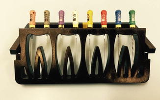
Fig. 9.3
Clinical photograph showing (a) stainless steel K-files. The K-files are available in ISO diameters from .06 to .140 mm and lengths from 21, 25 and 31 mm. The six colours (white, yellow, red, blue, green and black are repeated from size #15 to #140)
The K-flex file
The K-Flex file is made from a rhomboid or diamond-shaped blank. This hybrid file was manufactured in an attempt to integrate the strength and versatility of the K-file with the aggressive cutting properties of the H file.
The K-FlexoFile
These files are manufactured by twisting a steel wire with a triangular cross section. The FlexoFile tip is rounded and has a transitional angle that is blunted, making this instrument safer during the shaping of curved canals. The triangular section is less bulky than K-files, increasing the flexibility of the FlexoFiles. The FlexoFiles are only available in ISO diameters of 0.15–0.40 mm and lengths 21, 25 and 31 mm.
The K-FlexoFiles Golden Mediums
The K-FlexoFiles Golden Mediums are identical to the K-FlexoFiles except that the diameters have intermediate values compared to those of the ISO standard. The K-FlexoFiles Golden Mediums are available in ISO diameters 12, 17, 22, 27, 32 and 37; the lengths remain the same as conventional K-files of 21, 25 and 31 mm. Their use is recommended for long and calcified or curved canals where the passage from a 10 file to a 15 file or from a 15 file to a 20 file proves to be difficult. The use of intermediate diameters enables the operator to reach the working length easier and with less risk of iatrogenic complications.
The Flex-R file
Developed by Roane, this hybrid-type file attempts to incorporate characteristics of both K-file- and H-file-type instruments. It is produced by a grinding process similar to H files resulting in cross-sectional geometry similar to a K-file with a non-cutting tip designed with a compound angle of 70 and 35° without any active cutting edges. The modified tip and greater flexibility associated with these files allowed for a balanced force technique to be applied to mechanical preparation of curved canals with less canal transportation, ledging and perforation.
The C + files
The C + files are designed with a robust quadrangular which shows greater resistance to deformation compared to corresponding K-files. They are particularly useful in facilitating the location of the canal orifices and the initial exploration of calcified canals. The files are available in ISO diameters 8, 10 and 15 with lengths of 18, 21 and 25 mm.
Hedstroem file
The Hedstroem file is machined from a round tapered stainless steel blank, and the spiral flutes are cut into the shank, producing a sharp blade. Only a true filing action should be used with this instrument because of the angle of the blade and positive rake angle. Due to their inherent fragility, there is a strong possibility of fracture if a reaming action is used and the blades are engaged in the dentine. The H file is particularly useful for removing gutta-percha root fillings or smoothing dentinal walls or ledges (Fig. 9.4).
Fig. 9.4
Clinical photographs showing stainless steel K-file (K), Hedstroem file (H) and C+ File (C+). The K-file can be used in a reaming action. The H file should be used in a push-pull action. The C+ file shows greater resistance to deformation compared to the K-file due to its robust cross-sectional file design. It is available in ISO diameters 8, 10 and 15 with lengths of 18, 21 and 25 mm and is particularly useful for calcified canals
Barbed broach
This instrument is manufactured from a round wire with smooth surfaces, which can be notched to form barbs at angle to the long axis. The sharp rasps pointing towards the handle may be used to loosen or remove pulpal tissue remnants from within the root canal. The barbed broach is carefully introduced deep in the canal, twisted a quarter to a half turn and then withdrawn. Care must be excised not to force the instrument apically beyond the point at which it first binds since it can fracture easily.
Gates–Glidden drills
The Gates–Glidden drills are steel instruments used in a contra-angle slow hand-piece characterised by a long shank and an elliptical flame-shaped non-cutting tip. Gates–Glidden drills are available in six sizes and marked with corresponding circular notches. The #1 Gates–Glidden drill has a maximum diameter of 0.50 mm, which increases 0.20 mm for each successive size, until #6 which has a maximum diameter of 1.50 mm. The Gates–Glidden drills are designed with the weakest point at the start of the shank, so that they are easier to remove in case they fracture inside the root canal. It is very important to remember that the Gates #1 and #2 are very fragile and can fracture at the level of the tip, especially if the recommended rotational speed of 800 rpm is exceeded and if they are subjected to overzealous bending stresses.
The Gates drills must be used passively on withdrawal from the canal with a brush-like circumferential movement. Modification of the Gates–Glidden drill has been utilised in creating a staging platform when attempting to remove separated instruments within the straight portion of the canal (Fig. 9.5).
Stay updated, free dental videos. Join our Telegram channel
VIDEdental - Online dental courses


