Introduction
The aim of this study was to evaluate the effect of mini-implant diameter on fracture risk and self-drilling efficacy.
Methods
A sample of 405 mini-implants with 9 diameters from 1.2 to 2.0 mm was used. Ten mini-implants of each diameter were placed in artificial bone, and 25 were placed in pig iliac bone to evaluate placement torque (PT) and axial placement load (APL), which represents self-drilling efficacy. Ten mini-implants of each diameter were used to determine fracture torque (FT). The different diameters were compared regarding PT, FT, and APL. The fracture risk of each diameter was evaluated by the fracture resistance index (FT/PT × [FT-PT]). The PT and APL changes during placement were correlated.
Results
Only PT and FT were different for all mini-implant diameter changes. PT and FT showed a strong correlation with the mini-implant diameter, but the APL was weakly to moderately correlated. The fracture resistance index was remarkably greater for each 0.1 mm added in diameter. The PT increased significantly, whereas the APL was progressively reduced during placement.
Conclusions
Increases in mini-implant diameters significantly influenced the increases of PT and FT on quantities that progressively reduced the fracture risk. The self-drilling efficacy was not strongly influenced by diameter.
The self-drilling mini-implant has significantly reduced root damage risks because the bone drilling previously needed for mini-implant placement is not required. In addition, there are other clinical benefits of this drill-free protocol such as simpler surgical procedure, quicker mini-implant placement, no bone overheating, and greater primary stability and bone-to-metal contact. However, drill-free placement significantly increases placement torque and load; as a consequence, the fracture risk is also increased.
Mini-implant fracture might now be a more severe clinical complication than root contact. Because the fracture risk is in inverse proportion to the mini-implant’s diameter, the use of a thicker self-drilling mini-implant could reduce the fracture risk in critical placement sites and also improve screw stability. Nevertheless, the diameter increase can cause significantly greater placement torque and load during self-drilling; these could have an antagonistic effect on fracture risk reduction and self-drilling efficacy. Furthermore, thicker mini-implants have a greater potential risk for root damage or screw loss because of their close proximity to roots. Therefore, the choice of the mini-implant’s diameter requires better knowledge about its influence on several clinical factors to prevent accidents and complications, and increase the success rate of this anchorage system. Thus, we evaluated the effect of mini-implant diameter on fracture risk and self-drilling efficacy.
Material and methods
A sample of 405 mini-implants was standardized and especially manufactured for this study (Dentos, Daegu, South Korea). The mini-implants were equally distributed in 9 diameters that progressively increased from 1.2 to 2 mm, in increments of 0.1 mm. Ninety mini-implants (10 of each diameter) were placed to evaluate the maximum placement torque and axial placement load in artificial bone blocks with a moderate density of 0.48 g per cubic centimenter. Similarly, 225 mini-implants (25 of each diameter) were placed to evaluate the maximum placement torque and axial placement load in pig iliac bone blocks. The remaining 90 mini-implants (10 of each diameter) were placed in artificial bone blocks with a high density of 0.80 g per cubic centimeter to break the screws and to determine the fracture torque.
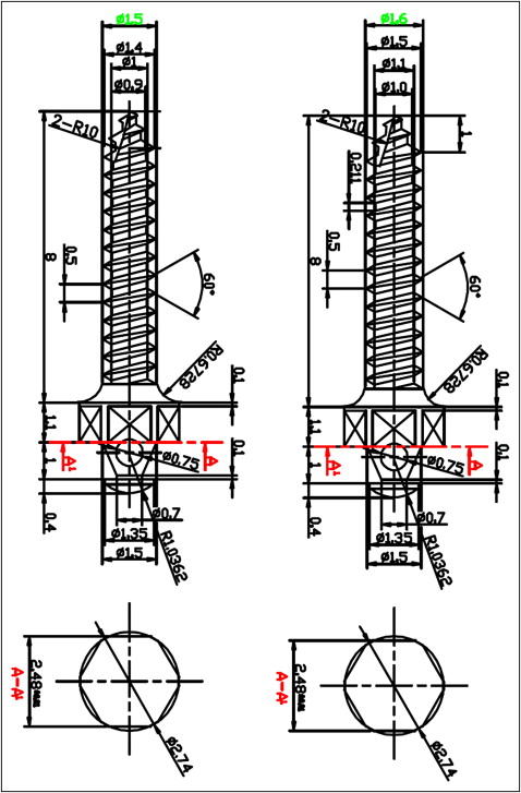
The 405 self-drilling mini-implants had an 8-mm thread length and were made of the same titanium alloy (titanium, aluminum, and vanadium). With the exception of nominal and core diameter changes, the mini-implant heads and the other structural and dimensional thread characteristics (pitch, flank angle, thread form, thread depth, and taper) were systematically standardized because they could significantly distort the effect of diameter on the evaluated variables and reduce the reliability of the results ( Fig 1 ).
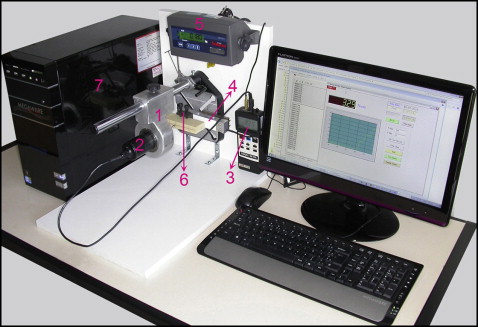
To simultaneously quantify the torque and load produced by placement and fracture procedures, an assay machine was specifically made for this study. This equipment had a torquimeter driver to prevent oblique placement forces during manual screw placement ( Fig 2 , 1 ). The digital torquimeter (TQ 680; Instrutherm Ltda, São Paulo, Brazil) ( Fig 2 , 2 and 3 ) working with a load cell (BSPL single point; Berman Load Cells, São Paulo, Brazil) ( Fig 2 , 4 and 5 ) allowed simultaneous torque and load measurements during screw placement in the test blocks, which were attached to a clamp ( Fig 2 , 6 ). A computer with specific software was used for compilation and analyses of the data sent by the torque and load sensors ( Fig 2 , 7 ).
The artificial bone made of polyurethane (Sawbones Division of Pacific Research Laboratories, Vashon Island, Wash) was selected because it met the requirements of the American Society for Testing and Materials (F-1839-08) and has been successfully used for biomechanical tests of bone screws.
Pig iliac bone was chosen for this experiment to reproduce the biomechanical characteristics of the jaw bones during mini-implant placement. The cortical thickness close to the iliosacral joint ranged from 0.5 to 1 mm, which is similar to the buccal cortical thickness in some anatomic regions of the human maxilla and mandible. Furthermore, this cortical thickness would allow drill-free placement and torque measurement for all evaluated mini-implant diameters without the risk of fractures.
The artificial bones were divided in blocks of 13 × 2 × 4 cm. The placement sites were previously marked and spaced about 20 mm apart.
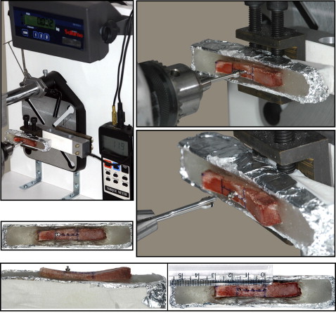
The iliac bone close to the iliosacral joint was segmented in blocks (10 × 2 × 3 cm) and embedded in resin to provide adequate size and resistance to the pig bone blocks during the experimental procedures. The specimens were cooled to prevent overheating from the self-curing resin. The placement sites were spaced about 4 mm from each other and the bone margin. Furthermore, the cortical thickness of the placement sites was restricted to an interval of 0.5 to 1 mm.
For the torque and load tests, the 405 mini-implants were placed without drilling. The torque and load sensors measured the torsional and axial forces applied by the operator (S.E.B.) during placement using Newtons per centimeter (Ncm) and gram-force (gf) units, respectively. A depth limiter was attached to the screwdriver to standardize the placement depth in the thread length limit ( Fig 3 ).
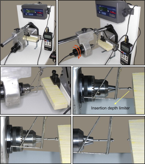
The screwdriver was fitted in the torquimeter, and the mini-implants were perpendicularly placed in the artificial (0.48 g/cm 3 ) and pig bone blocks by using the minimum load able to make self-drilling and screw threadings ( Figs 3 and 4 ). After placement, the compiled data about placement torque and axial placement load in the artificial and iliac bones were statistically evaluated. The placement torque and axial placement load changes during placement in the artificial and pig iliac bones were also evaluated. Additionally, the total changes in torque and axial load during all placement procedures in the artificial (0.48 g/cm 3 ) and pig iliac bones were calculated. Each pig bone block received mini-implants of the same diameter, linearly distributed and placed along the cortical surface to prevent an unbalanced distribution of the different diameters in the several cortical thicknesses (0.5-1 mm; Fig 4 ).
The fracture torque was determined by mini-implants placed in the high-density artificial bone (0.80 g/cm 3 ) to achieve a torque value able to cause torsional fracture of the screw.
The fracture resistance index (fracture torque/placement torque × [fracture torque – placement torque]) proposed in this study was used to evaluate the fracture risk. The axial placement load was the variable taken to represent self-drilling efficacy.
Statistical analyses
The Kruskal-Wallis test was used to compare mini-implant diameters. The torque and axial load values in each screw diameter were compared with the Mann-Whitney test.
Diameter was correlated with torque and axial load values by the Spearman correlation test, which was also used to correlate the torque and axial load changes during drill-free placement.
To evaluate the sensitivity of the fracture resistance index in predicting the fracture risk for each mini-implant diameter, a descriptive analysis of placement torque and fracture torque changes between the various diameters was made. A correlation graphic between mini-implant diameters and the expressions fracture torque/placement torque and fracture torque – placement torque was also obtained.
Results
The variables placement torque in artificial and iliac bones and fracture torque increased significantly for each 0.1-mm increase in diameter. The axial placement load in artificial bone showed a gradual increase toward the greater diameters, but without a statistical difference. The diameter increase showed an axial placement load in iliac bone progressively greater with significant differences, but not for all diameters ( Table I ).
| Diameter (mm) | PT-ab (Ncm) n = 10 | PT-ib (Ncm) n = 25 | APL-ab (gf) n = 10 | APL-ib (gf) n = 25 | FT (Ncm) n =10 |
|---|---|---|---|---|---|
| Mean (SD) | Mean (SD) | Mean (SD) | Mean (SD) | Mean (SD) | |
| 1.2 | 2.91 (0.38) A | 2.35 (0.41) A | 414.20 (56.51) | 1135.04 (173.27) A | 5.89 (0.36) A |
| 1.3 | 3.99 (0.17) B | 3.38 (0.51) B | 420.70 (36.86) | 1205.04 (130.44) B | 9.05 (0.53) B |
| 1.4 | 5.71 (0.24) C | 4.30 (0.62) C | 441.80 (67.66) | 1239.24 (132.23) C | 12.17 (0.32) C |
| 1.5 | 6.78 (0.46) D | 4.98 (0.91) D | 433.90 (40.87) | 1264.20 (99.17) C | 16.45 (0.41) D |
| 1.6 | 7.86 (0.29) E | 6.02 (1.05) E | 444.60 (44.29) | 1281.80 (101.44) C | 21.61 (0.51) E |
| 1.7 | 8.88 (0.40) F | 7.20 (1.04) F | 434.10 (48.30) | 1295.16 (167.03) C | 27.26 (0.88) F |
| 1.8 | 10.97 (0.29) G | 8.75 (1.51) G | 436.90 (46.77) | 1348.44 (177.25) D | 32.93 (1.00) G |
| 1.9 | 13.22 (0.29) H | 10.32 (1.73) H | 456.00 (38.29) | 1423.40 (119.01) E | 41.00 (2.18) H |
| 2.0 | 14.13 (0.43) I | 13.14 (2.07) I | 465.10 (34.55) | 1558.92 (191.50) F | 49.41 (2.20) I |
| P | <0.001 ∗ | <0.001 ∗ | 0.210 | <0.001 ∗ | <0.001 ∗ |
When the placement torque values in the 2 types of bone were compared, the value for artificial bone was significantly greater except for the 2-mm screw diameter. The fracture torque was significantly greater than the placement torque in artificial bone ( Table II ). If fracture torque is greater than placement torque in artificial bone and placement torque in artificial bone is greater than placement torque in iliac bone, then the following can be expressed: fracture torque is greater than placement torque in artificial bone, and that is greater than placement torque in iliac bone. The axial placement load in artificial bone was significantly less than in iliac bone for all screw diameters ( Table II ).
| Diameter (mm) | PT-ab × PT-ib | P | PT-ab × FT | P | APL-ab × APL-ib | P | |||
|---|---|---|---|---|---|---|---|---|---|
| Mean (Ncm) n =10 | Mean (Ncm) n = 25 | Mean (Ncm) n =10 | Mean (Ncm) n =10 | Mean (gf) n =10 | Mean (gf) n = 25 | ||||
| 1.2 | 2.91 | 2.35 | 0.003 ∗ | 2.91 | 5.89 | <0.001 ∗ | 414.20 | 1135.04 | <0.001 ∗ |
| 1.3 | 3.99 | 3.38 | <0.001 ∗ | 3.99 | 9.05 | <0.001 ∗ | 420.70 | 1205.04 | <0.001 ∗ |
| 1.4 | 5.71 | 4.30 | <0.001 ∗ | 5.71 | 12.17 | <0.001 ∗ | 441.80 | 1239.24 | <0.001 ∗ |
| 1.5 | 6.78 | 4.98 | <0.001 ∗ | 6.78 | 16.45 | <0.001 ∗ | 433.90 | 1264.20 | <0.001 ∗ |
| 1.6 | 7.86 | 6.02 | <0.001 ∗ | 7.86 | 21.61 | <0.001 ∗ | 444.60 | 1281.80 | <0.001 ∗ |
| 1.7 | 8.88 | 7.20 | <0.001 ∗ | 8.88 | 27.26 | <0.001 ∗ | 434.10 | 1295.16 | <0.001 ∗ |
| 1.8 | 10.97 | 8.75 | <0.001 ∗ | 10.97 | 32.93 | <0.001 ∗ | 436.90 | 1348.44 | <0.001 ∗ |
| 1.9 | 13.22 | 10.32 | <0.001 ∗ | 13.22 | 41.00 | <0.001 ∗ | 456.00 | 1423.40 | <0.001 ∗ |
| 2.0 | 14.13 | 13.14 | 0.400 | 14.13 | 49.41 | <0.001 ∗ | 465.10 | 1558.92 | <0.001 ∗ |
The diameter strongly influenced the variables of placement torque in both types of bone and fracture torque, showing an almost perfect correlation coefficient ( Table III ). A weak to moderate correlation was observed between the mini-implant diameter and the variables of axial placement load in both types of bone ( Table III ).
| r | P value | |
|---|---|---|
| Diameter × PT-ab | 0.992 | <0.001 ∗ |
| Diameter × PT-ib | 0.955 | <0.001 ∗ |
| Diameter × APL-ab | 0.303 | <0.01 ∗ |
| Diameter × APL-ib | 0.604 | <0.001 ∗ |
| Diameter × FT | 0.993 | <0.001 ∗ |
| ΔPT-ib × ΔAPL-ib | −0.824 | <0.001 ∗ |
| ΔPT-ab × ΔAPL-ab | −0.626 | <0.001 ∗ |
| ΔTT × ΔTAL | −0.785 | <0.001 ∗ |
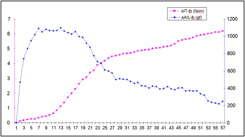
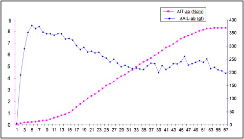
The placement torque and axial placement load changes during placement procedures in the iliac bone had a strong negative correlation; in the artificial bone, these changes showed a moderate negative correlation. When the changes in placement torque and axial placement load for all placement procedures were correlated, a strong negative correlation coefficient was obtained, highlighting that placement torque increased while axial placement load decreased during drill-free placement ( Table III ; Figs 5-7 ).