Introduction
The aim of this study was to determine whether the orthopedic forces of rapid maxillary expansion cause significant quantitative changes in the cranial and the circummaxillary sutures.
Methods
Twenty patients (mean age, 12.3 ± 1.9 years) who required rapid maxillary expansion as a part of their comprehensive orthodontic treatment had preexpansion and postexpansion computed tomography scans. Ten cranial and circummaxillary sutures were located and measured on one of the axial, coronal, or sagittal sections of each patient’s preexpansion and postexpansion computed tomography scans. Quantitative variables between the 2 measurements were compared by using the Wilcoxon signed rank test. A P value less than 0.05 was considered statistically significant.
Results
Rapid maxillary expansion produced significant width increases in the intermaxillary, internasal, maxillonasal, frontomaxillary, and frontonasal sutures, whereas the frontozygomatic, zygomaticomaxillary, zygomaticotemporal, and pterygomaxillary sutures showed nonsignificant changes. The greatest increase in width was recorded for the intermaxillary suture (1.7 ± 0.9 mm), followed by the internasal suture (0.6 ± 0.3 mm), and the maxillonasal suture (0.4 ± 0.2 mm). The midpalatal suture showed the greatest increase in width at the central incisor level (1.6 ± 0.8 mm) followed by the increases in width at the canine level (1.5 ± 0.8 mm) and the first molar level (1.2 ± 0.6 mm).
Conclusions
Forces elicited by rapid maxillary expansion affect primarily the anterior sutures (intermaxillary and maxillary frontal nasal interfaces) compared with the posterior (zygomatic interface) craniofacial structures.
Rapid maxillary expansion (RME) is indicated for the treatment of maxillary transverse deficiency. The expansion occurs when the force applied to the teeth and the maxilla exceeds the limits needed for tooth movement. The applied force causes widening and gradual opening of the midpalatal suture, compression of the periodontal ligament, bending of the alveolar processes, and dental tipping.
Although the main purpose of RME is to correct maxillary arch discrepancies, its effect is not limited to the maxillary alveolus and midpalatal suture but is expected to affect several other adjacent structures in the face and the cranium. The maxilla articulates with other skull bones through the cranial and circummaxillary sutures. Sutures in the skull have several functions. They unite bones, absorb forces, act as joints that permit relative movement between bones, and play a role as growth sites.
Several histologic investigations have studied sutural responses to orthopedic forces in monkeys, cats, rats, and biopsies from children. Histologically, the sutures of the maxilla are heavily affected by the orthopedic forces used in orthodontic treatment. Experimental separation of sutures in monkeys resulted in skeletal remodeling in all the circummaxillary sutures; the amount of remodeling appeared to be proportional to the suture’s distance from and orientation to the applied force. However, differences in sutural morphology, together with differences in sequence and degree of closure between humans and different animal species, bring doubt on the clinical application of the animal experiments.
Mechanical stresses induced by RME result in the transmission of forces that produce tensile and compressive strains on the facial bones and the adjacent structures. Craniomaxillary sutures, which then absorb and transmit these forces, are likely to be modified by these mechanical forces. Many investigators have pointed out that RME results in dramatic changes in the craniofacial structures. Gardner and Kronman in their RME study on rhesus monkeys found that the lambdoid, parietal, and midsagittal sutures of the vault of the cranium showed evidence of distortion, and in 1 animal a split of 1.5 mm was reported. Kudlick concluded that all craniofacial bones directly articulating with the maxilla were displaced, except the sphenoid bone. Wertz and Dreskin showed that the maxilla moved downward and usually forward during suture opening, whereas Timms showed that the maxilla and the palatine bones moved apart, along with the pterygoid processes of the sphenoid bone. Jafari et al in their 3-dimensional study on a finite element model of a human skull indicted that the transverse orthopedic forces of RME produced not only an expansive force at the intermaxillary suture but also high forces on various structures on the craniofacial complex, particularly the sphenoid and zygomatic bones.
Although a number of clinical and radiographic studies have evaluated the effects of RME on the craniomaxillary complex, only limited information is available on the response of the cranial sutures. Computed tomography (CT), as an imaging modality, offers many advantages over conventional radiographs, since it permits clear visualization of sections of the human body and the skull without overlap of structures. Therefore, the aim of this study, by using low-dose multiplanar CT scans, was to examine the effects of orthopedic forces on the cranial and circummaxillary sutures in adolescents treated with RME.
Material and methods
This prospective study included 20 patients with transverse maxillary deficiency. The patients’ ages ranged from 8 to 15 years (mean, 12.3 ± 1.9 years). They were treated by RME with the hyrax appliance as part of their comprehensive orthodontic treatment. The appliance design required banding 4 teeth (2 maxillary first premolars or deciduous first molars and 2 maxillary first molars). The appliance screw was activated 2 quarter turns (0.2 mm/turn) twice a day until the required amount of expansion was achieved and the palatal cusp of the maxillary first molar contacted the buccal cusp of the mandibular first molar. The appliance was left in situ as a passive retainer for 3 months, after which it was removed. The study was approved by the ethical committee of the dental faculty, Al-Azhar University of Cairo, Egypt, and each parent signed an informed consent form.
The spiral CT machine (model X, vision; GE Medical Systems, Milwaukee, Wis) was used to obtain pre-RME (T1) CT images before orthodontic treatment and post-RME (T2) images immediately after the hyrax appliance was removed. The CT scans were made at 120 kV and 20 mA, with a scanning time of 2 seconds per section. Scan parameters included an A2-90 scanning filter, a 25-cm field of view, and a matrix of 512 × 512 pixels. The window width was 2400 Hounsfield units with a center of 1300 Hounsfield units. The machine’s perpendicular light beam was used to standardize the head position in all 3 planes and thus allow comparison of the images before and after expansion. The scans were taken of each patient in the supine position, with the palatal plane perpendicular to the ground. The subject was positioned so that the longitudinal light beam passed through the center of the glabella and the philtrum, and the transverse light beam passed through the lateral eye canthi. One-millimeter thick axial sections were made parallel to the palatal plane, incorporating the dentoalveolar and the basal areas of the maxilla up to the cranial base.
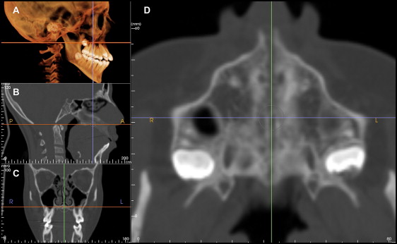
The digital imaging and communications in medicine (DICOM) images for each patient were assessed by using the InVivo Dental imaging software program (Anatomage, San Jose, Calif). Ten cranial and circummaxillary sutures ( Fig 1 ) were precisely located and measured in width on 1 axial, coronal, or sagittal section of the CT scans showing the greatest width and according to the orientation of the suture ( Figs 2-6 ). The location of each suture was determined in reference to its location on the 3-dimensional volumetric model by adjusting the cursor over the same reference point for T1 and T2; subsequently, the corresponding location on the different sections (axial, coronal, and sagittal) was updated.
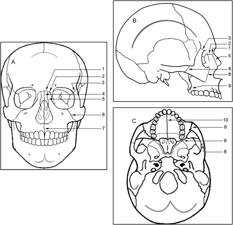
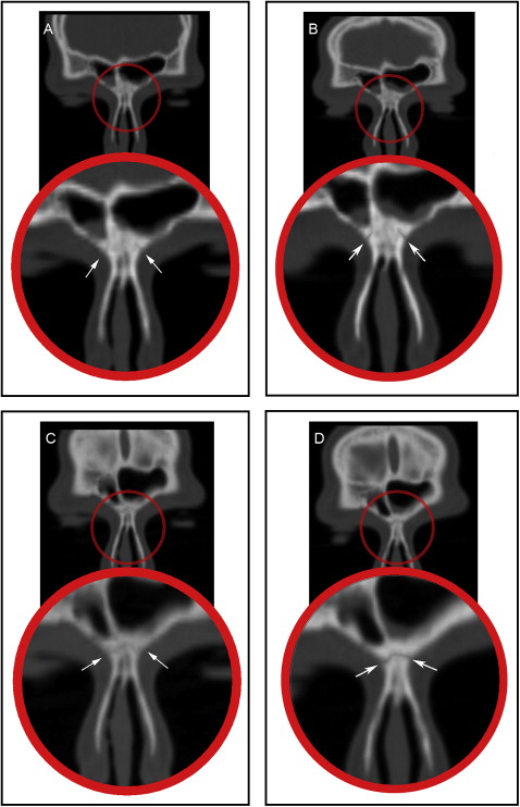
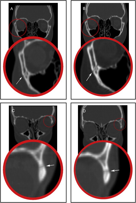
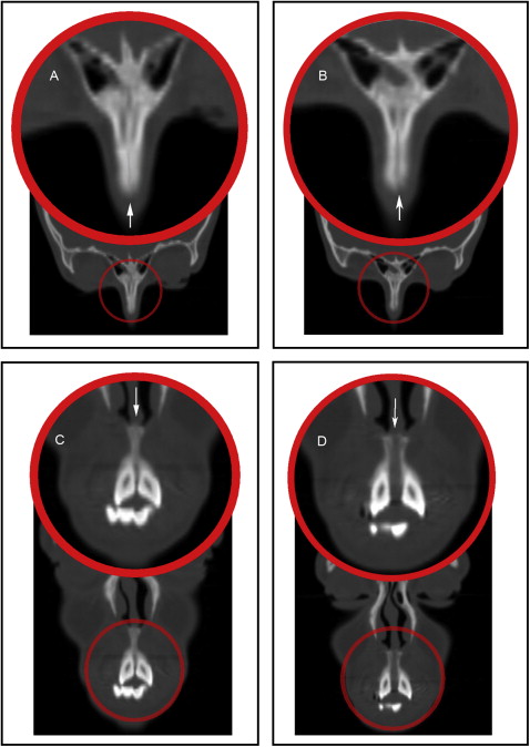
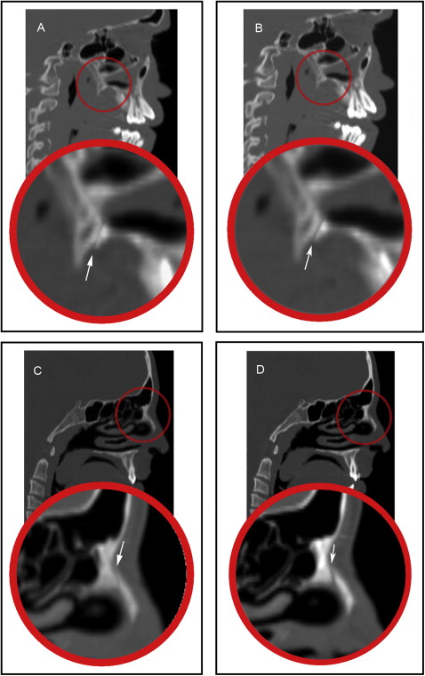
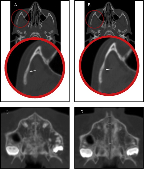
The frontomaxillary, frontonasal, frontozygomatic, zygomaticomaxillary, internasal, and intermaxillary sutures were located and measured on the coronal sections ( Figs 2-4 ). The internasal suture was measured on a 45° clockwise rotated coronal section to represent the full length of the suture. The pterygomaxillary and the nasomaxillary sutures were located and measured on the sagittal sections ( Fig 5 ). T1 and T2 measurements were determined for each suture by measuring the width of the radiolucent area located between the 2 bony edges at the middle of the suture. The difference between T2 and T1 indicates the increase or decrease in the suture width.
The midpalatal and zygomaticotemporal sutures were evaluated on the axial section ( Fig 6 ). The midpalatal suture was measured at the level of the maxillary permanent central incisors, canines, and first molars. The exact location of the maxillary central incisors, canines, and first molars was determined with the marker (cursor) feature in the Anatomage software, which can show the exact corresponding position of the teeth on the axial section from a reference level on the coronal section ( Fig 7 ). The difference between T2 and T1 indicates the change and the amount of suture opening.
All measurements were performed twice at a 2-week interval by the same examiner (A.G.). Differences between the 2 readings for intraexaminer variation were tested by using paired t tests. The results were based on the averages of the 2 readings. Descriptive statistics (means and standard deviations) were obtained for each variable at T1 and T2, and for the changes from T2 to T1. Within-group comparisons of quantitative variables between T1 and T2 were made by using the Wilcoxon signed rank test. A probability value less than 0.05 was considered statistically significant. All statistical calculations were done by using the computer programs Excel 2007 (Microsoft, Redmond, Wash) and the Statistical Package for the Social Science (version 15; SPSS, Chicago, Ill) for Windows.
Results
The intraexaminer reliability test showed no statistically significant difference between the 2 readings. Descriptive statistics for the measurements at T1 and T2 and for the changes from T2 to T1 are presented in Tables I and II . The comparison of the changes represents the overall treatment effect.
| T1 | T2 | Change | P value | ||||||||||
|---|---|---|---|---|---|---|---|---|---|---|---|---|---|
| Mean | SD | Max | Min | Mean | SD | Max | Min | Mean | SD | Max | Min | ||
| Frontozygomatic width Rt (mm) | 0.6 | 0.3 | 1.2 | 0.1 | 0.6 | 0.3 | 1.2 | 0.2 | 0.0 | 0.0 | 0.2 | 0.1 | 0.065 |
| Frontozygomatic width Lt (mm) | 0.6 | 0.3 | 1.3 | 0.2 | 0.7 | 0.3 | 1.3 | 0.2 | 0.1 | 0.1 | 0.3 | 0.1 | 0.063 |
| Frontomaxillary width Rt (mm) | 0.6 | 0.2 | 0.9 | 0.4 | 0.7 | 0.2 | 1.3 | 0.4 | 0.1 | 0.1 | 0.8 | 0.1 | 0.006 ∗ |
| Frontomaxillary width Lt (mm) | 0.6 | 0.2 | 1.0 | 0.4 | 0.7 | 0.3 | 1.6 | 0.4 | 0.1 | 0.2 | 1.5 | 0.1 | 0.003 ∗ |
| Zygomaticomaxillary width Rt (mm) | 0.5 | 0.1 | 0.8 | 0.3 | 0.6 | 0.1 | 0.8 | 0.5 | 0.1 | 0.1 | 0.3 | 0.1 | 0.055 |
| Zygomaticomaxillary width Lt (mm) | 0.5 | 0.1 | 0.8 | 0.3 | 0.6 | 0.1 | 0.8 | 0.4 | 0.1 | 0.1 | 0.2 | 0.1 | 0.055 |
| Zygomaticotemporal width Rt (mm) | 0.6 | 0.3 | 1.4 | 0.5 | 0.7 | 0.2 | 1.5 | 0.6 | 0.0 | 0.1 | 0.2 | 0.1 | 0.065 |
| Zygomaticotemporal width Lt (mm) | 0.6 | 0.3 | 1.3 | 0.4 | 0.7 | 0.2 | 1.3 | 0.5 | 0.0 | 0.1 | 0.3 | 0.1 | 0.065 |
| Pterygomaxillary width Rt (mm) | 0.5 | 0.1 | 0.8 | 0.3 | 0.6 | 0.2 | 0.9 | 0.4 | 0.1 | 0.2 | 0.6 | 0.2 | 0.065 |
| Pterygomaxillary width Lt (mm) | 0.5 | 0.2 | 0.9 | 0.3 | 0.6 | 0.2 | 1.0 | 0.4 | 0.1 | 0.2 | 0.7 | 0.1 | 0.065 |
| Frontonasal width Rt (mm) | 0.5 | 0.2 | 0.9 | 0.2 | 0.7 | 0.2 | 1.1 | 0.4 | 0.2 | 0.1 | 0.6 | 0.1 | <0.001 ∗ |
| Frontonasal width Lt (mm) | 0.5 | 0.2 | 0.9 | 0.3 | 0.7 | 0.2 | 1.1 | 0.5 | 0.2 | 0.1 | 0.6 | 0.1 | <0.001 ∗ |
| Nasomaxillary width Rt (mm) | 0.5 | 0.1 | 0.8 | 0.4 | 0.9 | 0.2 | 1.5 | 0.6 | 0.4 | 0.2 | 1.0 | 0.1 | <0.001 ∗ |
| Nasomaxillary width Lt (mm) | 0.6 | 0.1 | 0.8 | 0.4 | 1.0 | 0.2 | 1.5 | 0.7 | 0.4 | 0.2 | 1.1 | 0.1 | <0.001 ∗ |
| Internasal width (mm) | 0.5 | 0.1 | 0.7 | 0.3 | 1.1 | 0.3 | 1.9 | 0.7 | 0.6 | 0.3 | 2.7 | 0.5 | <0.001 ∗ |
| Intermaxillary width (mm) | 0.5 | 0.1 | 0.6 | 0.2 | 2.2 | 0.9 | 4.3 | 1.1 | 1.7 | 0.9 | 3.6 | 0.6 | <0.001 ∗ |
Stay updated, free dental videos. Join our Telegram channel
VIDEdental - Online dental courses


