Introduction
The purpose of this study was to evaluate the skeletal and dental changes in the maxillae of patients with clefts treated with 3 expanders: hyrax, fan-type, and inverted mini-hyrax supported on the first premolars.
Methods
Thirty patients with unilateral cleft lip and palate with transverse maxillary deficiency were divided into 3 groups, according to the type of expander that they used. Cone-beam computed tomography images were taken before and 3 months after expansion, and the paired t test was used to evaluate the changes in each group.
Results
The subjects in the inverted mini-hyrax group showed significant forward displacement of the maxilla ( P <0.05). On the transversal plane, the hyrax group showed greater expansion in the posterior region than in the anterior region ( P <0.05). However, the fan-type and the inverted mini-hyrax groups showed significantly greater maxillary expansion anteriorly than posteriorly ( P <0.05). There was a greater tendency for buccal inclination of the supporting teeth when the fan-type was used. The cleft and the noncleft sides expanded symmetrically with all appliances, and there was no difference in dental tipping between these sides ( P >0.05).
Conclusions
The hyrax expander showed better results for cleft patients requiring anterior and posterior maxillary expansion. The inverted mini-hyrax most effectively restricted posterior expansion, optimizing anterior expansion without causing as much buccal tipping of the supporting teeth as did the fan-type.
Cleft lip and palate (CLP) is the most prevalent among all craniofacial anomalies, affecting one in every 700 births and disturbing the quality of life of more than 7 million people around the world. Patients with CLP have lip and alveolus repair surgeries during the first years of life and, later, repairs to the hard and soft palates. As a consequence, the growth and development of the maxillary segments are compromised by scar tissues, thus inducing maxillary constriction, particularly in the anterior region. Rapid maxillary expansion (RME) is commonly used to correct this transverse deficiency. Often, the goal of RME for many cleft patients has been to increase the anterior maxillary expansion and restrain the posterior expansion, since there is a greater anterior than posterior maxillary constriction in most of these patients.
Alternative RME appliances have been used to enhance the expansion in the anterior region of the maxillary arch. However, no studies have confirmed this benefit in cleft patients, and only clinical observations have been described in some case reports. Therefore, imaging studies are required to confirm or refute the effectiveness of these alternative expanders in enhancing anterior maxillary expansion in CLP patients and to confirm their actual dentoskeletal effects.
Therefore, the aim of this study was to evaluate the dentoskeletal effects of 3 maxillary expanders: the conventional hyrax and 2 modified types, especially designed to promote anterior expansion of the maxillary arch. The null hypothesis to be tested was that there are no differences in the type and amount of expansion with these 3 appliances.
Material and methods
Approval for this study was obtained from the institutional review board of the Pontifical Catholic University of Minas Gerais, Brazil. Signed informed consents were obtained from all patients and their parents. The study sample comprised 30 children (16 boys, 14 girls) with unilateral CLP (UCLP) who sought orthodontic treatment at the center for treatment of craniofacial anomalies at this university. The selection criteria included UCLP, need for maxillary expansion, and no previous orthodontic intervention. The exclusion criteria were any additional craniofacial syndrome, no maxillary permanent first molars, deciduous molars or canines with accentuated mobility, and active periodontal disease. Each patient’s stage of cervical vertebral maturation was assessed; all patients were before or at the growth spurt (CS1-CS4).
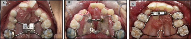
The subjects were distributed into 3 groups (10 patients each), according to the extension of the maxillary deficiency. The subjects with anterior and posterior maxillary deficiency received the hyrax expander. The ones with only anterior maxillary deficiency were treated with either the fan-type or the inverted mini-hyrax expander. Because of the characteristics of the inverted mini-hyrax expander, only patients with fully erupted first premolars were included in this group. The sex and age distributions for all groups are shown in Table I . The hyrax is a tooth-borne appliance with a jackscrew (Leone Orthodontics and Implantology, Firenze, Italy) located mesial to the maxillary permanent first molars ( Fig 1 , A ). The fan-type expander is a tooth-and-tissue borne appliance with a jackscrew and a posterior hinge (Morelli Ortodontia, Sorocaba, Brazil) located in the region of the permanent first molars ( Fig 1 , B ). The inverted mini-hyrax is a tooth-borne appliance constructed with a mini-hyrax screw (Dynaflex, Saint Ann, Mo) positioned in the anterior region, with its arms bent posteriorly and soldered to the first premolar bands bilaterally. It was used with a transpalatal arch (TPA) inserted at the permanent first molars ( Fig 1 , C ). The same laboratory technician fabricated all expanders.
| Group | Age (y) | Sex | Cleft side | |||
|---|---|---|---|---|---|---|
| Mean | SD | Male | Female | Right | Left | |
| Hyrax | 11.3 | 2.4 | 7 | 3 | 4 | 6 |
| Fan-type | 10.5 | 1.8 | 6 | 4 | 2 | 8 |
| Inverted mini-hyrax | 12.3 | 2.3 | 3 | 7 | 4 | 6 |
A pretreatment (T0) cone-beam computed tomography (CBCT) scan, rather than conventional radiographs, was obtained as part of the patients’ initial orthodontic records. Each expander was cemented with a fluoride-releasing cement (Ultra Band-Lok; Reliance Orthodontic Products, Itasca, Ill), and the activation regimen was established at 2 turns per day until the tip of the lingual cusps of the maxillary teeth touched the tips of the buccal cusps of the mandibular teeth. After the 3-month retention period, the expander was removed, a postexpansion (T1) CBCT scan was acquired, and a TPA with anteriorly extending arms was immediately inserted to serve as a retainer until the next phase of orthodontic treatment. Obtaining the CBCT at T1 was justified because of its importance for adequate secondary bone graft surgical planning.
The same radiology technician captured all tomographic scans using an i-CAT machine (Imaging Sciences International, Hatfield, Pa). The scans were performed at 120 kV, 8 mA, scan time of 40 seconds, and 0.3-mm voxel dimension. All CBCT images were oriented and standardized using Dolphin software (version 11.5; Dolphin Imaging & Management Solutions, Chatsworth, Calif). The images of each patient’s head were oriented in all 3 planes of space for frontal, right lateral, and top (facing down) views. In the frontal view of reconstruction orientation, the axial plane should coincide with the right and left frontozygomatic sutures. In the right lateral view, the axial plane must coincide with the Frankfort horizontal plane. In the top view, the midsagittal plane should coincide with the line connecting crista galli and basion.
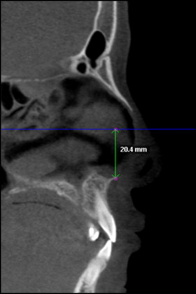
The RME effects were examined to compare the measurements made at T0 and T1 in all 3 planes of space. The changes in the anteroposterior plane were assessed using the SNA angle measured in the lateral cephalograms obtained from the CBCT scans. The variations in the vertical plane were analyzed using CBCT sagittal slices, measuring the lesser distance between the Frankfort horizontal line and the anterior nasal spine ( Fig 2 ). The effects on the transverse dimension were evaluated with axial and coronal cuts. The transverse posterior maxillary measurements were registered on the permanent first molars, and the transverse anterior measurements were recorded at the level of the most anterior appliance-supporting teeth. When the roots were used as a reference, the palatal roots were selected for both molars and premolars. The following parameters were used to quantify the transverse changes.
- 1.
Dental crown width (DCW): the transverse width at the coronal slices between the most prominent lingual area of the right and left posterior (Pt-DCW) and anterior (At-DCW) teeth ( Fig 3 , A ). The actual landmarks could be slightly different at different times because of the inclination of the teeth during treatment.
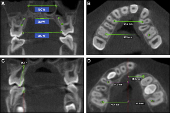
Fig 3 Transversal measurements. A, Coronal slice showing DCW, DAW, and NCW. The same procedure was performed for the anterior appliance-supported teeth. B, Axial slice showing At-MBW and Pt-MBW. C, Coronal slice showing posterior tipping. The same procedure was performed for the cleft and noncleft sides in the posterior and anterior regions. D, Measurements of lateral displacements between the cleft and noncleft sides ( right , cleft side; left , noncleft side). - 2.
Maxillary basal width (MBW): the maxillary right first molar was identified at the axial slice. A landmark was placed in the center of the palatal root canal at the level of root separation. In the same slice, another landmark was placed in the root canal of the most anterior appliance-supporting tooth. The same procedure was performed on the left side. A line between the 2 landmarks in the posterior teeth determined the posterior MBW (Pt-MBW). A second line connecting the landmarks in the anterior teeth determined the anterior MBW (At-MBW) ( Fig 3 , B ).
- 3.
Dental apices width (DAW): the transverse width at the coronal section between posterior teeth apices (Pt-DAW) and between anterior teeth apices (At-DAW) ( Fig 3 , A ).
- 4.
Nasal cavity width (NCW): To measure the posterior NCW (Pt-NCW), the palatal root apex of the right permanent first molar was located at the coronal section. In the same slice, a landmark was placed on the right lateral wall at the widest portion of the nasal cavity. Using a line parallel to the floor passing through the first landmark, a second landmark was placed on the left lateral wall of the nasal cavity. The Pt-NCW was defined as the distance between these 2 points. The procedure was performed for the nasal width at the anterior region (At-NCW), using the right anterior tooth root apex as a reference ( Fig 3 , A ).
- 5.
Dental tipping (Tip): at the coronal section, 2 lines were used to calculate the tipping angle. The first line was perpendicular to the axial plane passing through the root apex. The second line was drawn passing through the palatal cusp tip and the palatal root apex. Dental tipping was obtained at the right and left sides of the posterior (Pt-Tip) and anterior (At-Tip) teeth ( Fig 3 , C ). Even using the root apex for this measure, the root resorption of the deciduous teeth was not considered because of the short time between T0 and T1. Furthermore, RME does not influence the rate of resorption of deciduous teeth used as anchorage.
To evaluate which maxillary segment was expanded more, the same landmarks described for the MBW measurement were used. A midsagittal line connecting crista galli and basion was defined as the reference line. In the axial slice, the lesser distance from this midsagittal line to the 4 MBW landmarks was measured ( Fig 3 , D ).
Statistical analysis
The same operator (D.S.F.F.), who was blinded to the group status, made all measurements. To test intraexaminer reproducibility, the same examiner reassessed the raw images and remeasured 18 random images at least 1 week later, and the results were compared with the original measurements. The intraexaminer reliability values were determined using the intraclass correlation coefficient, which varied between 0.98 and 0.99, indicating high reproducibility of the measurements.
Descriptive statistics, including means and standard deviations, were calculated for all measurements. The paired t test was used to evaluate whether the changes from T0 to T1 were significantly different in each group. The paired t test was also used to evaluate differences in transverse changes between the anterior and posterior regions for each expander and differences in alveolar expansion and dental tipping between the cleft and noncleft sides. The data obtained from all measurements were processed with GraphPad software (version 5.01; GraphPad Software, La Jolla, Calif). The level of significance for all statistical tests was predetermined at 5%.
Results
There was no statistically significant movement of the maxilla in either the vertical or the anteroposterior plane ( P >0.05) when the hyrax and fan-type appliances were used. However, in the inverted mini-hyrax group, a significant forward maxillary displacement ( P <0.05) was registered, as shown in Tables II through IV .
| Measurement | T0 | T1 | Mean of difference (T1−T0) | P value | 95% CI | ||
|---|---|---|---|---|---|---|---|
| Mean | SD | Mean | SD | ||||
| Anteroposterior | |||||||
| SNA (°) | 81.77 | 6.68 | 81.75 | 4.96 | −0.02 | NS | −1.86 to 1.82 |
| Vertical | |||||||
| FH-ANS (mm) | 17.13 | 2.19 | 17.86 | 1.96 | 0.73 | NS | −0.69 to 2.15 |
| Transverse | |||||||
| Anterior maxilla | |||||||
| DCW (mm) | 19.65 | 2.62 | 24.34 | 3.59 | 4.69 | <0.05 | 3.76 to 5.62 |
| MBW (mm) | 25.95 | 2.35 | 29.80 | 3.05 | 3.85 | <0.05 | 2.70 to 5.00 |
| DAW (mm) | 26.84 | 2.65 | 29.64 | 3.91 | 2.80 | <0.05 | 1.45 to 4.14 |
| NCW (mm) | 25.15 | 3.17 | 26.74 | 2.87 | 1.59 | <0.05 | 1.01 to 2.16 |
| Dental tip CS (°) | −3.73 | 14.88 | 0.21 | 14.19 | 3.94 | NS | −3.31 to 11.19 |
| Dental tip NCS (°) | 3.99 | 9.12 | 12.50 | 8.17 | 8.51 | <0.05 | 3.29 to 13.73 |
| Posterior maxilla | |||||||
| DCW (mm) | 30.47 | 2.20 | 35.20 | 2.53 | 4.73 | <0.05 | 3.92 to 5.53 |
| MBW (mm) | 38.15 | 2.59 | 42.49 | 2.63 | 4.34 | <0.05 | 3.49 to 5.18 |
| DAW (mm) | 29.74 | 3.33 | 33.49 | 2.61 | 3.75 | <0.05 | 2.73 to 4.76 |
| NCW (mm) | 29.41 | 2.85 | 31.28 | 2.67 | 1.87 | <0.05 | 0.80 to 2.94 |
| Dental tip CS (°) | 13.02 | 4.57 | 13.82 | 5.12 | 0.80 | NS | −0.27 to 1.87 |
| Dental tip NCS (°) | 11.37 | 3.17 | 13.74 | 4.55 | 2.37 | <0.05 | 0.27 to 4.46 |
| Measurement | T0 | T1 | Mean of difference (T1−T0) | P value | 95% CI | ||
|---|---|---|---|---|---|---|---|
| Mean | SD | Mean | SD | ||||
| Anteroposterior | |||||||
| SNA (°) | 80.00 | 5.12 | 79.53 | 4.85 | −0.47 | NS | −2.31 to 1.36 |
| Vertical | |||||||
| FH-ANS (mm) | 3.03 | 4.28 | 3.17 | 4.40 | 0.14 | NS | −0.01 to 0.29 |
| Transverse | |||||||
| Anterior maxilla | |||||||
| DCW (mm) | 21.09 | 2.36 | 27.20 | 4.49 | 6.11 | <0.05 | 3.71 to 8.50 |
| MBW (mm) | 26.54 | 2.04 | 30.87 | 3.47 | 4.33 | <0.05 | 2.38 to 6.28 |
| DAW (mm) | 26.61 | 3.45 | 27.84 | 3.55 | 1.23 | <0.05 | 0.62 to 1.84 |
| NCW (mm) | 26.99 | 2.76 | 28.81 | 2.31 | 1.82 | <0.05 | 0.37 to 3.27 |
| Dental tip CS (°) | −5.93 | 11.17 | 12.47 | 10.75 | 18.40 | <0.05 | 6.80 to 30.00 |
| Dental tip NCS (°) | −1.75 | 10.75 | 12.15 | 10.02 | 13.90 | <0.05 | 6.41 to 21.39 |
| Posterior maxilla | |||||||
| DCW (mm) | 32.46 | 3.38 | 35.62 | 2.67 | 3.16 | <0.05 | 2.17 to 4.15 |
| MBW (mm) | 39.95 | 2.99 | 42.72 | 2.09 | 2.77 | <0.05 | 1.68 to 3.86 |
| DAW (mm) | 30.64 | 2.06 | 31.65 | 1.59 | 1.01 | NS | −0.28 to 2.30 |
| NCW (mm) | 30.38 | 2.84 | 31.89 | 2.94 | 1.51 | <0.05 | 0.67 to 2.34 |
| Dental tip CS (°) | 13.98 | 6.33 | 17.64 | 4.61 | 3.66 | <0.05 | 0.47 to 6.84 |
| Dental tip NCS (°) | 13.29 | 3.34 | 17.00 | 4.23 | 3.71 | <0.05 | 1.52 to 5.90 |
| Measurement | T0 | T1 | Mean of difference (T1−T0) | P value | 95% CI | ||
|---|---|---|---|---|---|---|---|
| Mean | SD | Mean | SD | ||||
| Anteroposterior | |||||||
| SNA (°) | 79.38 | 5.27 | 80.54 | 4.71 | 1.16 | <0.05 | 0.16 to 2.17 |
| Vertical | |||||||
| FH-ANS (mm) | 6.54 | 9.17 | 6.24 | 8.42 | −0.30 | NS | −0.91 to 0.31 |
| Transverse | |||||||
| Anterior maxilla | |||||||
| DCW (mm) | 23.32 | 2.17 | 27.26 | 2.50 | 3.93 | <0.05 | 2.78 to 5.08 |
| MBW (mm) | 28.69 | 3.07 | 31.98 | 3.96 | 3.28 | <0.05 | 1.94 to 4.63 |
| DAW (mm) | 29.50 | 3.80 | 32.38 | 5.16 | 2.87 | <0.05 | 1.01 to 4.74 |
| NCW (mm) | 31.34 | 3.47 | 31.94 | 3.39 | 0.60 | NS | −0.81 to 2.01 |
| Dental tip CS (°) | −10.00 | 12.92 | −7.68 | 17.74 | 2.31 | NS | −4.06 to 8.68 |
| Dental tip NCS (°) | −1.98 | 13.08 | −0.96 | 12.65 | 1.02 | NS | −3.24 to 5.28 |
| Posterior maxilla | |||||||
| DCW (mm) | 34.83 | 2.71 | 35.20 | 2.38 | 0.36 | NS | −0.11 to 0.84 |
| MBW (mm) | 42.39 | 3.38 | 42.70 | 3.22 | 0.31 | <0.05 | 0.07 to 0.54 |
| DAW (mm) | 32.34 | 6.02 | 32.44 | 3.78 | 0.10 | NS | −3.11 to 3.31 |
| NCW (mm) | 32.50 | 4.82 | 33.49 | 4.44 | 0.98 | <0.05 | 0.43 to 1.54 |
| Dental tip CS (°) | 15.46 | 7.85 | 14.37 | 6.85 | −1.08 | NS | −3.16 to 0.98 |
| Dental tip NCS (°) | 13.26 | 4.91 | 12.44 | 5.87 | −0.81 | NS | −2.98 to 1.35 |
Stay updated, free dental videos. Join our Telegram channel
VIDEdental - Online dental courses


