Introduction
The purpose of this study was to evaluate the treatment effects of maxillary posterior tooth distalization performed by a modified palatal anchorage plate appliance with cephalograms derived from cone-beam computed tomography.
Methods
The sample consisted of 40 lateral cephalograms obtained from the cone-beam computed tomography images of 20 Class II patients (7 men, 13 women; average age, 22.9 years) who underwent bilateral distalization of their maxillary dentition. The lateral cephalograms were derived from the cone-beam computed tomography images taken immediately before placement of a modified palatal anchorage plate appliance and at the end of distalization. Paired t tests were used for comparisons of the changes.
Results
The distal movement of the maxillary first molar was 3.3 ± 1.8 mm, with distal tipping of 3.4° ± 5.8° and intrusion of 1.8 ± 1.4 mm. Moreover, the maxillary incisors moved 3.0 ± 2.7 mm lingually, with lingual tipping of 6.2° ± 7.6° and insignificant extrusion (1.1 mm; P = 0.06). The occlusal plane angle was increased significantly ( P = 0.0001).
Conclusions
The maxillary first molar was distalized by 3.3 mm at the crown and 2.2 mm at root levels, with distal tipping of 3.4°. It is recommended that clinicians should consider using the modified palatal anchorage plate appliance in treatment planning for patients who require maxillary total arch distalization.
Extraoral appliances have been prescribed for maxillary molar distalization in nonextraction treatment of Class II malocclusion patients. However, these devices require patient cooperation. To effectively overcome this problem, intraoral noncompliance appliances have been developed. Nevertheless, the negative side effects of these appliances include anchorage loss at the reactive part, distal tipping, and extrusion of molars.
To reduce the drawbacks of noncompliance appliances, temporary skeletal anchorage devices (TSADs) have been applied to the buccal plate of the bone to achieve molar distalization. However, the buccal approach poses an increased risk of contacting the roots of adjacent teeth, and the range of action might be limited by the interradicular space. Sugawara et al placed plates at the zygomatic buttresses for distalization of the maxillary dental arch. However, their method involved surgical procedures and a latency time between the surgery and force application.
Recently, palatal bone thickness and density as well as palatal soft-tissue thickness have been evaluated in adults and adolescents. These studies have provided detailed information for the placement of the TSADs in the palate. In addition, the placement of the TSADs in the palate eliminates the need for reimplanting miniscrews as in the buccal approach.
Several appliances with TSADs have been reported to distalize the maxillary posterior teeth, but some were bulky and others contributed to distal crown tipping. Kinzinger et al proposed a distal jet appliance supported by dental and skeletal anchorages. Although it reduced the anchorage loss, it prevented movement of the premolars during the distalization period. Kircelli et al used a bone-anchored pendulum appliance. A large amount of distal tipping of the first molar (10.9°) was reported with this appliance; this could have been due to a force vector similar to the conventional appliance. On the other hand, the modified palatal anchorage plate (MPAP) appliance has been reported to effectively distalize the posterior teeth in adults and adolescents. Finite element analysis suggested that distalization with a palatal plate rather than buccally placed mini-implants provides bodily molar movement without tipping or extrusion. However, no clinical evaluation has been performed with the MPAP.
So far, most distalization studies have used 2-dimensional lateral cephalograms. The disadvantages of this approach include confounded images caused by superimposed anatomic structures, vertical and horizontal magnifications, and a lack of right and left side information. Although cone-beam computed tomography (CBCT) has disadvantages that include higher doses of radiation, higher cost, and limited availability, these limitations are overcome by the huge amount of data that is provided without distortion or superimposition.
The degree of difficulty and the prognosis of distalization are affected by the patient’s dental and chronologic ages. A high success rate with fewer complications occurs when the maxillary molars are distalized in the mixed dentition stage. Hence, most distalization studies have focused on adolescents, and there have been no studies, to the best of our knowledge, investigating the distalization effect in adults who have full eruption of their maxillary second molars.
Therefore, the purpose of this study was to evaluate the treatment effects of posterior tooth distalization in adults with an MPAP appliance using lateral cephalograms derived from CBCT images.
Material and methods
Forty lateral cephalograms were obtained from CBCT images of 20 consecutively treated Class II adult patients (7 men, 13 women; average age, 22.9 years; range, 17.4-33 years) who underwent bilateral distalization of their maxillary dentition at the Department of Orthodontics at Seoul St. Mary’s Hospital, Catholic University of Korea. Of the 40 lateral cephalograms, 15 sides had one quarter cusp, 12 had one half cusp, 7 had three quarters cusp, and 6 had full cusp Class II molar relationships.
The inclusion criteria for this retrospective study were (1) dental Class II relationship, (2) 3-dimensional CBCT images taken immediately before and after distalization, (3) exclusive use of the MPAP appliance for distalization, and (4) age over 17 years. The exclusion criteria were (1) extraction treatment (except for third molars) and (2) unilateral distalization. Approval was obtained from the institutional review board of the Catholic University of Korea (KC11RASI0790), and informed consent was provided according to the Declaration of Helsinki.
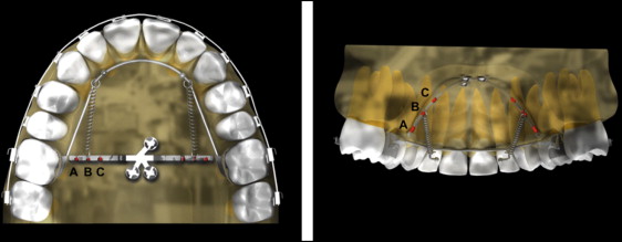
The MPAP appliance ( Fig 1 ) and its installation method have been described in previous articles. The MPAP was fitted on the dental cast to the shape of the palate, extending its arms to the area between the first molar and the second premolar and leaving enough space between the arms and the palatal slopes. The transfer from the cast to the patient’s mouth was made with a jig by the same operator (Y.-A.K.) using 3 miniscrews (length, 8 mm; diameter, 2 mm: Jeil, Seoul, Korea). Then a palatal bar with 2 hooks extending along the gingival margins of the teeth was banded to the right and left maxillary first molars. Immediately after placement, distalization can be initiated by engaging elastics or nickel-titanium closed-coil springs between the MPAP arm notches and the hooks on the palatal bar, applying approximately 300 g of force per side.
Along with the MPAP appliance, 0.022-in slot brackets and bands (Tomy, Tokyo, Japan) were placed on the maxillary and mandibular teeth including the second molars. The interval between appointments was 3 to 4 weeks. The distalization periods were calculated from the patients’ records.
CBCT images (before and after distalization) were taken with an iCAT scanner (Imaging Science International, Hatfield, Pa). The scanning parameters were 120 kV, 47.7 mAs, 20 seconds per revolution, 170 × 130 mm field of view, and voxel size of 0.4 mm. Each seated subject’s head position was oriented so that the Frankfort plane was parallel to the floor, and the images were taken at the intercuspal position.
The CBCT data were exported in a digital imaging and communications in medicine (DICOM) multifile format and imported into InVivo software (version 5.2; Anatomage, San Jose, Calif) for 3-dimensional volume rendering. Reorientation of the head position of each scan was performed as follows. The horizontal plane (x) was defined through the right and left orbitales and the left porion, and the midsagittal plane (y) was defined as the perpendicular plane passing through nasion and anterior nasal spine. The vertical plane (z) was perpendicular to both x and y. Then, using the super-ceph module in the InVivo software, a lateral cephalometric image was created for each right and left side independently and saved in JPG format. Each image was then traced and superimposed using V-Ceph software (version 5.5; Cybermed, Seoul, South Korea) with the manual geometric method. The horizontal reference line was the Frankfort horizontal plane, and the vertical reference line was the perpendicular at pterygoid. All tracings and digitizations were made by 1 examiner (V.T.T.T.) to minimize operator-generated variation in the measurements.
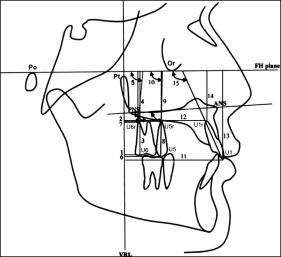
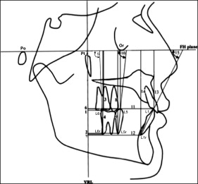
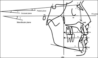
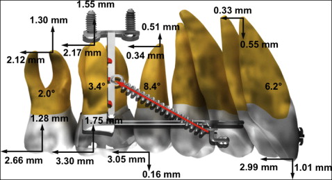
The software calculated the linear and angular dimensions between certain landmarks according to the definitions given in Figures 2 through 4 .
The maxillary third molar was present in 31 sides and extracted or missing from 9 sides during treatment.
Ten randomly selected subjects were reprocessed 4 weeks later to evaluate intraoperator reliability. The intraclass correlation coefficient showed that the measurements were reliable (>0.997).
Statistical analysis
Statistical evaluation was performed using SPSS software (version 16.0; SPSS, Chicago, Ill). Normal distribution of the parameters was assessed with the Kolmogorov-Smirnov test. The paired t test was used to evaluate the skeletal, dental, and soft-tissue changes from before to after distalization. The comparison between subjects who had third molars during distalization and those with missing or extracted ones was performed by an independent sample t test. The statistical significance was determined at α = 0.05.
Results
Clinically successful distalization was achieved using the MPAP appliance for an average of 12.5 months.
There were significant changes in the sagittal and vertical positions ( P <0.0001) and angulations ( P = 0.001) of the maxillary first molars after distalization. The mean amount of first molar distalization was 3.30 ± 1.80 mm, with distal tipping of 3.42° ± 5.79° and intrusion of 1.75 ± 1.35 mm. The maxillary second molar showed 2.66 ± 1.90 mm of distalization, 1.28 ± 1.61 mm of intrusion, and 2.03° ± 7.49° of distal tipping. The maxillary second premolars moved distally 3.05 ± 2.14 mm and tipped distally 8.38° ± 6.80°, with no significant change in the crown vertical position. The maxillary central incisors were retracted by 2.99 ± 2.73 mm, with a retroclination angle of 6.21° ± 7.64° and no significant change in the vertical position ( Table I , Fig 5 ).
| Variable | Predistalization | Postdistalization | Change | P value | |||
|---|---|---|---|---|---|---|---|
| Mean | SD | Mean | SD | Mean | SD | ||
| Central incisor crown horizontal distance (mm) | 55.22 | 5.32 | 52.23 | 5.52 | 2.99 | 2.73 | <0.001 |
| Central incisor root horizontal distance (mm) | 47.21 | 3.77 | 46.89 | 3.97 | 0.33 | 2.08 | 0.327 |
| Central incisor crown vertical distance (mm) | 54.52 | 4.57 | 55.61 | 4.20 | −1.09 | 3.51 | 0.056 |
| Central incisor root vertical distance (mm) | 35.17 | 3.46 | 35.72 | 3.43 | −0.55 | 1.92 | 0.077 |
| Central incisor inclination (°) | 68.15 | 10.47 | 74.36 | 10.34 | −6.21 | 7.64 | <0.001 |
| Second premolar crown horizontal distance (mm) | 33.14 | 5.21 | 30.09 | 4.94 | 3.05 | 2.14 | <0.001 |
| Second premolar root horizontal distance (mm) | 33.61 | 3.87 | 33.26 | 4.03 | 0.34 | 2.21 | 0.332 |
| Second premolar crown vertical distance (mm) | 49.88 | 4.69 | 50.04 | 4.13 | −0.16 | 3.91 | 0.798 |
| Second premolar root vertical distance (mm) | 33.26 | 5.20 | 32.75 | 3.63 | 0.51 | 3.61 | 0.381 |
| Second premolar angulation (°) | 92.11 | 7.22 | 100.49 | 8.66 | −8.38 | 6.80 | <0.001 |
| First molar crown horizontal distance (mm) | 18.43 | 4.42 | 15.13 | 4.17 | 3.30 | 1.80 | <0.001 |
| First molar root horizontal distance (mm) | 22.99 | 3.48 | 20.82 | 3.53 | 2.17 | 1.85 | <0.001 |
| First molar crown vertical distance (mm) | 45.51 | 4.08 | 43.76 | 4.63 | 1.75 | 1.35 | <0.001 |
| First molar root vertical distance (mm) | 31.53 | 3.74 | 29.98 | 3.78 | 1.55 | 1.96 | <0.001 |
| First molar angulation (°) | 109.30 | 6.05 | 112.72 | 7.83 | −3.42 | 5.79 | 0.001 |
| Second molar crown horizontal distance (mm) | 9.23 | 3.93 | 6.57 | 3.74 | 2.66 | 1.90 | <0.001 |
| Second molar root horizontal distance (mm) | 16.00 | 3.13 | 13.88 | 3.19 | 2.12 | 1.90 | <0.001 |
| Second molar crown vertical distance (mm) | 42.56 | 4.75 | 41.28 | 5.15 | 1.28 | 1.61 | <0.001 |
| Second molar root vertical distance (mm) | 30.97 | 3.91 | 29.67 | 4.03 | 1.30 | 1.45 | <0.001 |
| Second molar angulation (°) | 120.67 | 10.05 | 122.71 | 9.36 | −2.03 | 7.49 | 0.118 |
The occlusal plane angle was significantly ( P = 0.001) increased by 2.81°. However, the palatal plane angle was not changed. The upper and lower lips showed about 1.5 mm of retraction ( P = 0.016 and 0.008, respectively). The nasolabial angle was significantly ( P = 0.008) increased to 101.9° ( Table II ).
| Variable | Predistalization | Postdistalization | Change | P value | |||
|---|---|---|---|---|---|---|---|
| Mean | SD | Mean | SD | Mean | SD | ||
| SNA (°) | 81.18 | 3.35 | 80.42 | 3.22 | 0.76 | 1.95 | 0.097 |
| ANB (°) | 4.38 | 2.11 | 3.36 | 1.80 | 1.01 | 1.46 | 0.006 |
| Palatal plane angle (°) | 5.96 | 17.50 | 9.31 | 3.08 | −3.35 | 16.81 | 0.384 |
| Occlusal plane to SN (°) | 18.78 | 6.33 | 21.60 | 5.94 | −2.81 | 3.37 | 0.001 |
| Mandibular plane angle (°) | 23.90 | 8.96 | 24.46 | 9.00 | −0.55 | 2.58 | 0.351 |
| ANS-Me (mm) | 67.43 | 6.01 | 68.62 | 6.44 | −1.19 | 3.26 | 0.120 |
| Overjet (mm) | 4.71 | 1.67 | 3.54 | 0.90 | 1.17 | 1.90 | 0.013 |
| Overbite (mm) | 3.28 | 1.44 | 3.16 | 1.15 | 0.13 | 1.64 | 0.735 |
| Nasolabial angle (°) | 98.64 | 7.69 | 101.90 | 8.38 | −3.26 | 4.87 | 0.008 |
| Mentolabial fold (°) | 135.53 | 9.74 | 133.36 | 9.02 | 2.17 | 6.39 | 0.145 |
| LS-VRL (mm) | 67.22 | 5.04 | 66.04 | 5.01 | 1.18 | 1.99 | 0.016 |
| LI-VRL (mm) | 63.70 | 5.86 | 62.16 | 5.87 | 1.54 | 2.33 | 0.008 |
| Pog′-VRL (mm) | 42.38 | 9.77 | 41.82 | 9.92 | 0.56 | 2.91 | 0.398 |
Stay updated, free dental videos. Join our Telegram channel
VIDEdental - Online dental courses


