Fig. 6.1
Different shapes of osteotomes used during crestal SFE
Osteotomes are surgical instruments that can be used effectively to enhance the placement of dental implants. The term “osteotome” means a bone-cutting or bone-deforming instrument.
They are generally wedge-shaped instruments with varied steepness of taper, designed to compress, cut, or deform bone. They are available with flat blades, pointed tips, concave (cupped) and convex (round shape) end:
-
The round (convex) osteotomes are mainly used for bone compression, especially at the beginning of the crestal SFE in presence of narrow ridges or soft bone.
-
Bladed osteotomes can be used to cut into the cortex of bone to split the cortices apart or segment a portion of narrow crest.
-
A pointed-end osteotome can be used to advance and widen the osteotomy in less dense bone. The cortex must be drilled wide enough to accommodate the osteotome so the instrument does not meet resistance.
-
Concave osteotomes are used to collect and compress bone into the apical end of the osteotomy. They are mostly used during crestal OSFE procedures.
-
Flat-ended osteotomes can compress (but not collect) bone fragments for increased density and are generally used in the anterior maxilla.
Osteotomes can be lubricated with saline or sterile water to facilitate movement through tissue. Round osteotomes should be used with straight, in-and-out movements to prevent the osteotomies from assuming an oval shape. This shape would jeopardize implant healing and/or osseointegration.
Osteotomes are optimally used by pressing the instrument into the bone and malleting only when there is slight resistance. Firmer resistance requires the use of a drill to widen the cortex: most resistance is caused by a too small cortical opening that prevents the osteotome to easily pass through (Flanagan 2006).
P.S.: An inappropriate use of the osteotomes (excessive malleting force) may lead to a labyrinthine concussion that lasts 1–3 weeks. However, some patients may require specific treatment in the form of head maneuvers to reposition the otoliths (Fig. 6.2a–c).
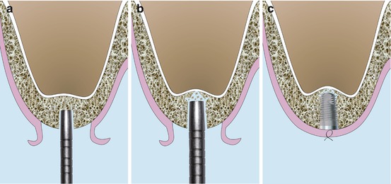
Fig. 6.2
Schematic drawings illustrating the original’s Summers technique (OSFE). (a) Concave osteotome introduced 2 mm beneath the sinus floor. (b) Larger osteotome pushing up the sinus floor via the residual bone. (c) Implant placement showing the bone apically to the implant lifting the sinus floor
In brief, the Summers technique is performed in the following way:
-
A midcrestal incision where buccal and palatal mucoperiostal flaps are reflected in a full-thickness approach exposing the crestal part of alveolar ridge.
-
The implant sites are marked with a 2.0 mm round drill and then prepared with a drill to a depth of 0.5–1.5 mm from the sinus floor.
-
The osteotomes are then selected to expand the preparation area both horizontally and vertically, achieving the initial sinus up-fracture. The osteotome itself should never penetrate the maxillary sinus.
-
The expansion of the osteotomy sites is performed with a number of Concave tipped tapered osteotomes with increasing diameters that are applied through the edentulous alveolar crest at the inferior border of the maxillary sinus floor. With each insertion of a larger osteotome, bone is compressed, pushed laterally and apically while pushing the garnered bone apically beneath the tented membrane.
Clinically, the tenting effect provides a space leading the advance of a bone mass (bone substitute or blood clot formation) beyond the level of the original sinus floor.
-
Osteotomes are marked at the corresponding implant lengths and with progressively larger diameters (0.5 mm increments).
This is similar to the green stick fracture method, which adds 2–3 mm of bone height beneath the elevated but unsullied sinus membrane.
A mallet is used, when needed, on the osteotome to expand the bone. The instrument is turned after each push of the mallet to prevent the tip from binding in the bone; the osteotome is maintained in a precise axial position as it is turned; a controlled pressure is needed to prevent the osteotomes from advancing more than 1 mm with each impact of the mallet avoiding the sinus floor perforation. (Some osteotome kits are proposed with stoppers for this purpose.) (Summers 1998).
The sinus elevation is delayed until the osteotome with the final apical diameter is used at the desired working depth. Once the largest osteotome has expanded the implant site. The sinus floor fracture is obtained with the final osteotome, punching out the cortical plate of sinus floor with the adherent sinus membrane (Checchi et al. 2010).
If after several mallet strikes and the osteotome do not progress, the surgeon should go back to a smaller-sized osteotome or use a drill.
This intrusion procedure produces a fracture in the least traumatic way possible. The osteotome technique is superior to drilling for many applications in soft maxillary bone. Furthermore, it allows more implants to be inserted in a greater variety of sites during a routine office procedure.
In the first three articles (Summers 1994a, b, c), Summers described the use of osteotome hand instruments to lift the sinus. The osteotome procedures that were introduced compressed soft maxillary bone, widened narrow ridge segments (ridge expansion osteotomy REO technique), and elevated the sinus floor for immediate implant insertion (osteotome sinus floor elevation OSFE and bone-added osteotome sinus floor elevation BAOSFE surgery).
In 1995, Summers (1995) also introduced a new means of intruding the ridge crest with larger osteotomes to create broader areas of sinus floor elevation, known as the future site development (FSD procedure). A bone plug is defined with a trephine and displaced superiorly with the use of a broad osteotome.
6.2 Modifications of the “Original” Technique (OSFE Summers 1994c)
6.2.1 Bone-Added Osteotome Sinus Floor Elevation (BAOSFE) (Fig. 6.3a–c)
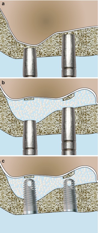
Fig. 6.3
Schematic drawings illustrating the BAOSFE technique. (a) Concave osteotome introduced 1–2 mm beneath the sinus floor. (b) Bone particles filling the created space beneath the sinus membrane. (c) Implants stabilized in the residual bone with their apical part surrounded by bone chips
Summers (1994b) combined the original OSFE procedure with the addition of a bone graft material, called the BAOSFE, as he considered it to be more conservative and less invasive than the lateral approach. It should be noted that in this technique, the bone substitutes are blindly introduced into the space below the sinus membrane.
Pressure on the graft material and trapped fluids exert hydraulic pressure on the sinus membrane, creating a blunt force over an expanded area that is larger than the osteotome tip (Chen et al. 2007). The sinus membrane is then less exposed to tearing with such a fluid consistent pressure, avoiding direct application of a hard surgical instrument (Summers 1994b).
Many reports have proposed modifications to Summers’ original BAOSFE (bone-added osteotome sinus floor) protocol to expedite the procedure, minimize malleting force, and simplify sinus floor infracture. Other authors have suggested modifications to the BAOSFE procedure in terms of instrumentation, grafting materials, and implant surface and design (Figs. 6.4, 6.5, 6.6, 6.7, and 6.8).
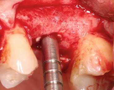
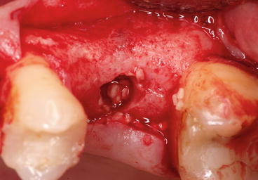
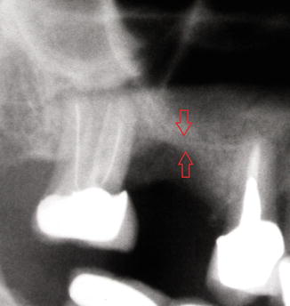

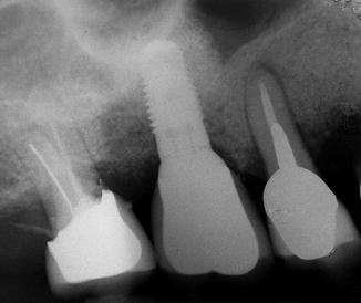
Fig. 6.4
Grafting material introduced upward with controlled osteotome pressure
Fig. 6.5
Bone chips progressively filled into the site prepared by the osteotome
Fig. 6.6
Preoperative X-ray showing the initial residual bone height (3 mm). The red arrows indicate the RBH between the top of the crest and the sinus floor
Fig. 6.7
Postoperative X-ray showing a tapered implant placed into the augmented sinus
Fig. 6.8
1-year postoperative radiograph showing the final bone level after loading
6.2.2 Modified Osteotome Technique (Drills + Osteotomes + BS) (Fig. 6.9a–c)
Fig. 6.9
Schematic drawings illustrating the modified osteotome technique. (a) Pilot drill initiating the SFE preparation avoiding the sinus floor. (b) Concave osteotome kept beneath the sinus floor while pushing up added bone substitutes mixed with the residual fragmented autogenous bone. (c) Implant surrounded by particulate bone substitute mixed with autogenous bone; note the intact lifted sinus membrane apically
In the presence of a dense sub-sinus bone quality, with no need to improve it further, the use of the osteotomes following Summers technique would be considered harmful for the patient. The use of 2 and 3 mm twist drills might be used initially to reach just 1–2 mm below the hard cortical plate of the sinus floor. Because further condensation of osseous tissue is deemed unnecessary in such cases, drilling alone would be more efficient and timesaving. The sinus floor is then “fractured” with #2 and #3 osteotomes by malleting.
For this purpose, in 1996, a new sequence of surgery based on the combined use of osteotomes, drills, and screw-type implants with a rough surface texture was proposed (Davarpanah et al. 2001).
This technique is indicated where the RBH ≥5 mm. The authors detailed the operative protocol as follows:
No instrument (osteotome, drill) should penetrate the sinus cavity during any part of the procedure.
-
The positioning of the implants is carried out with a round bur, and the preparation of the site begins with a 2 mm twist drill (pilot drill) and maintained to a distance of only 2–3 mm,
-
The 3 mm twist drill completes the preparation of the implant site for a standard-diameter implant.
-
The drilling must remain 1 mm below the floor of the sinus.
-
Radiographic control helps to confirm the integrity of the sub-sinus floor.
-
Grafting material is introduced into the surgical site before using the first osteotome (Summers No. 3 osteotome). This material will serve as a shock absorber to gently fracture the sinus floor.
The fracture is performed at the end with the largest instrument that corresponds to the size of the implant to be placed. Direct contact of the instruments with the sinus membrane is avoided since bone particles or a combination of autogenous bone and bone substitutes are immediately added after the sinus floor infracture on the top of the instruments into the developing space (Diserens et al. 2006).
At this stage, the integrity of the sinus membrane is confirmed by asking the patient to blow through the nose (after pinching the nostrils) and looking for mist on the mirror (Valsalva maneuver). If the sinus membrane has been perforated, two options can be considered: stop the operation and wait 4 weeks of healing prior to resuming the procedure or continue using a lateral approach.
-
The bone is progressively condensed using an osteotome.
-
With each use of the osteotome to condense the material, the sinus membrane is lifted approximately 1 mm.
The “modified osteotome technique” eliminated unnecessary hammering in the presence of a dense sub-sinus residual bone and therefore proved to be more tolerable to patients.
6.2.3 Modified Trephine/Osteotome Approach (Simultaneous Implant Placement) (Fig.6.10a–c)
Fig. 6.10
Schematic drawings of modified trephine/osteotome approach. (a) Trephine preparing a crestal bone core. (b) Concave osteotome pushing the resulting crestal bone core. (c) Implant placement lifting the bone core and the overlying sinus membrane upwards
Fugazzotto (2002) presented a technique in which a trephine with a 3.0 mm external diameter is utilized instead of a drill (or an osteotome) as a first step, followed by an osteotome to implode a core of residual alveolar bone prior to simultaneous implant placement.
-
This technique could be utilized either following a flap reflection or using a flapless approach.
-
A calibrated trephine bur with 3.0 mm external diameter is used to prepare the site to within approximately 1–2 mm of the sinus membrane at a reduced cutting speed.
-
Following removal of the trephine bur, if the bone core is found to be inside the trephine, it’s gently removed from the trephine and replaced in the alveolar bone preparation.
-
A calibrated osteotome corresponding to the diameter of the trephine preparation is used under gentle malleting forces, to implode the trephine bone core to a depth approximately 1 mm less than that of the prepared site.
-
The widest osteotome utilized will be one drill size narrower than the normal implant site preparation.
-
Implant placement induces a lateral dispersion of the imploded alveolar core with gentle and controlled displacement.
This technique both lessen the patient’s trauma and preserve a maximum amount of alveolar bone at the precise site of anticipated implant placement.
This technique is indicated in the presence of 4–5 mm of RBH in order to avoid repeated traumatic malleting of the osteotomes and is always combined to simultaneous implant placement (Figs. 6.11,.6.12, 6.13, and 6.14).
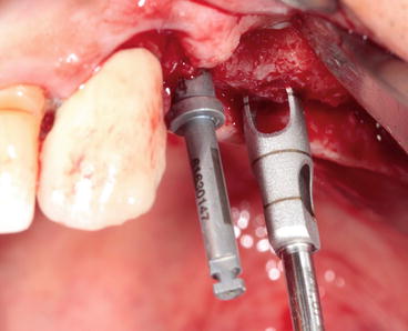
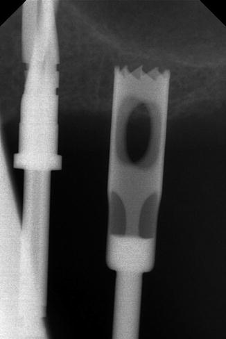
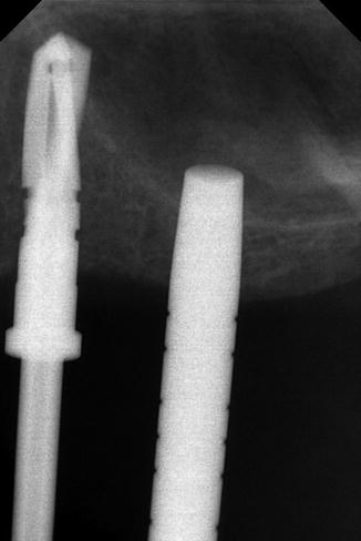
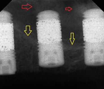
Fig. 6.11
Graduated trephine drill preparing the bone core at the selected implant site
Fig. 6.12
X-ray showing the trephine drill remaining 1 mm below the sinus floor
Fig. 6.13
X-ray of the osteotome imploding the trephine bone core into the sinus cavity
Fig. 6.14
Postoperative X-ray showing the original sinus floor (yellow arrows) and the imploded bone core apical to the implant (red arrows). Note the use of “trabecular metal technology” to optimize the bone ingrowth
6.2.4 Cosci Technique
The crestal approach technique has been also modified by Cosci and Luccioli (2000). Cosci technique is a one-stage crestal SFE approach using a specific sequence of atraumatic drills of varying lengths.
The shape of the drill tip prevents perforation of the sinus membrane and permits gentle abrasive removal of the cortical bone of the sinus floor without fracture.
Description of Cosci technique:
-
If the RBH is 6–7 mm:
-
A dedicated trephine drill of 3 mm diameter is initially used for the first 2–4 mm.
-
The dedicated 3 mm long and 2 mm diameter pilot drill is then used.
-
Followed by the 3 mm long intermediate and 3.1 mm diameter drill and by one or more atraumatic lifting drills of the actual height of the ridge as measured on the radiograph.
-
-
If the residual bone height is 4–5 mm: the trephine drill is not used, and the site is initially prepared with the dedicated 3 mm long and 2 mm diameter pilot drill, the rest of the preparation procedure being identical.
After using the first atraumatic lifting drill, the site is probed with a blunt instrument to feel the presence of the Schneiderian membrane. If the presence of bone is felt, a 1 mm longer atraumatic lifting drill is used, and so on, until the sinus lining is felt.
With a special rounded probe, a check of the alveolar bone is made to determine the integrity of the sinus membrane as well as the Valsalva maneuver (nose-blowing test).
Then, the graft is gently pushed into the site using a particular instrument called “body lifting”; this step is repeated until the site is filled with the graft (Bernardello et al. 2011).
Referring to the author (Cosci), the Cosci technique required, on average, almost 10 min less to be completed than the Summers technique; knowing that “harmful” osteotomes are not used, this technique might be preferred by the patients and the operators.
Drills used to prepare the implants site and lift the sinus lining according to the Cosci technique. Eight atraumatic SFE drills are available in the kit with incremental lengths of 1 mm starting from 5 and up to 12 mm (Fig. 6.15).
Fig. 6.15
Dr Cosci’s “noninvasive” sinus lift kit
6.3 Modifications of Summers Technique (OSFE) with Delayed Implant Placement
The prerequisite to simultaneous implant placement is to achieve a primary stability, depending on bone quantity and quality.
Crestal approach (Summers) could be applied without implant placement in two situations:
1.
By first intention when we consider that the bone volume is insufficient to insure primary implant stability.
2.
By second intention when we fail to ensure a primary stability while placing the implant.
6.3.1 Future Site Development (FSD) Technique
This technique, described by Summers (1994c) is indicated where the RBH is less than 5 mm. The placement of the implant is deferred until 7–9 months (Summers) after the SFE. The operative protocol is as follows.
-
A 2 mm diameter drill is used with the aid of a surgical guide.
-
A trephine with a 5 mm internal diameter is used to produce a cylinder of bone, which is displaced with a Summers No. 5 osteotome.
-
The sinus membrane is then elevated with this cylinder of bone, which acts as a shock absorber. The integrity of the sinus membrane must be confirmed. If it is perforated, the procedure should be discontinued.
Autogenous bone (with or without bone substitute) is progressively inserted until the necessary volume of sub-sinus bone has been achieved.
The FSD technique could also be used without trephine, especially when we have a reduced RBH (<4 mm) (Figs. 6.16, 6.17, 6.18, 6.19, and 6.20).
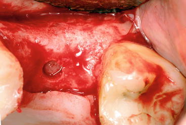
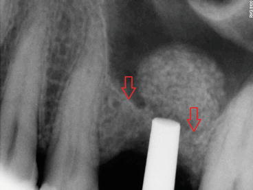
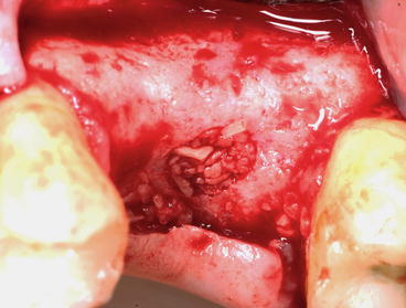
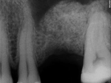
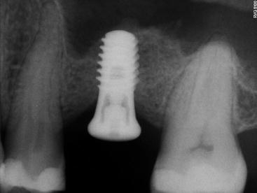
Fig. 6.16
Reduced residual bone height initiated with a concave osteotome
Fig. 6.17
Preoperative radiograph showing particulate bone substitute intruded incrementally through the osteotomy site. The arrows indicate the initial sinus floor
Fig. 6.18
Clinical view showing osteotomy site filled with particulate bone substitute
Fig. 6.19
Postoperative radiograph showing substantial sinus lifting gain
Fig. 6.20
5 months later, implant is placed in the regenerated sinus (allograft)
In multiple edentulous sectors, with the presence of septa combined to a reduced RBH, we may perform two entries either of the septum in order to avoid membrane perforation that may happen when using a lateral approach (Figs. 6.22 and 6.23).
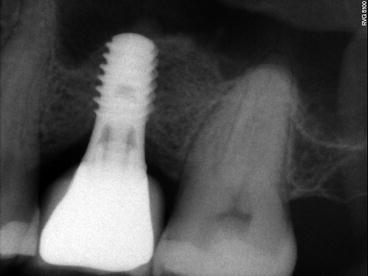
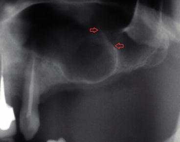
Fig. 6.21
1-year follow-up showing the minimal shrinkage of the regenerated bone
Fig. 6.22
Preoperative radiograph showing the presence of a “knife-edge” septum (red arrows)
6.3.2 Modified Trephine/Osteotome Sinus Augmentation Technique (Post-extraction Molars and Premolars) (Fig. 6.24a–b)
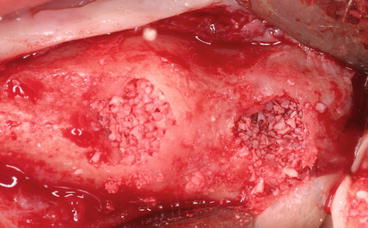
Fig. 6.23
Two crestal entries (anterior and posterior to the septum) prepared using a concave osteotome
Fugazzotto (1999) described a technique for accomplishing both localized SFE and guided bone regeneration at the time of maxillary molar extraction.
-
After the atraumatic extraction of the molar in a manner so as to preserve interradicular bone, a calibrated trephine bur is placed over the interradicular bone, which is of sufficient dimension to encompass both the interradicular septum and approximately 50 % of the extraction sockets (each trephine bur is approximately 1 mm thick).
-
Based on preoperative radiographs, measurement of removed roots and residual ridge morphology as guides, the clinician uses the trephine to prepare a site to within approximately 1–2 mm of the sinus membrane.
-
If the bone core is retained inside the trephine after its removal, it is gently pulled out and replaced in the alveolar bone preparation.
-
An osteotome is selected according to the diameter of the trephine preparation: gentle malletting forces implode both the trephined interradicular bone and the underlying sinus membrane to a depth at least equal to the apico-occlusal dimension of the trephined bone core.
-
The residual extraction socket is filled with bone substitutes.
-
An appropriate membrane is secured with fixation tacks.
-
Flaps are sutured so as to achieve passive primary closure.
This technique combines SFE procedure with GBR at the time of molar extraction in order to regenerate bone both buccolingually and apico-occlusally for an optimal implant positioning (delayed).
6.3.3 Minimally Invasive Antral Membrane Balloon Elevation (MIAMBE)
The presence of septa in maxillary sinus requires modification of surgical technique and carries a higher complication rate. Minimally invasive antral membrane balloon elevation (MIAMBE) is one of many modifications of the BAOSFE method, originally described by Soltan and Smiler (2005), in which antral membrane elevation is executed via the osteotomy site using a dedicated balloon.
After drilling depth is determined according to measurements obtained from the CT scan:
-
A pilot drill pilot (2 mm diameter) is introduced in the center of the alveolar crest up to 1–2 mm below the sinus floor.
-
The osteotomy is enlarged with the dedicated osteotomes.
-
Bone substitute (BS) is injected into the site, and subsequently, the sinus floor is gently fractured.
-
The membrane integrity is assessed. BS is injected again and a screw tap is tapped into the prepared site 2 mm beyond the sinus floor.
-
After screw-tap removal and evaluation of sinus membrane integrity, the metal sleeve of the balloon-harboring device is inserted into the osteotomy 1 mm beyond the sinus floor.
-
The balloon is inflated slowly with the barometric inflator up to 2 atm. Once the balloon emerged from the metal sleeve underneath the sinus membrane, the pressure dropped down to 0.5 atm.
-
Subsequently, the balloon is inflated with progressively higher volume of contrast fluid.
-
Sequential periapical X-rays evaluate the balloon inflation and membrane elevation. Once the desired elevation (usually 10 mm) is obtained, the balloon should be left inflated 5 min to reduce the sinus membrane recoil.
-
Then, the balloon is deflated and removed. The membrane integrity is assessed by direct visualization and examination with the suction syringe and respiratory movement of blood within the osteotomy site.
Implant placement at the same sitting is optional if the RBH is sufficient (Figs. 6.25, 6.26, and 6.27).
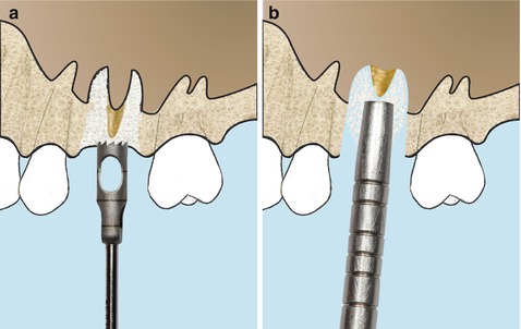
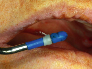
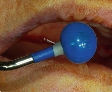
Fig. 6.24
Schematic drawings of the modified trephine/osteotome sinus augmentation technique. (a) Sinus floor is intruded by applying a trephine technique. (b) Intrusion of the interradicular bone using osteotomes
Fig. 6.25
Pneumatic device consisting of a syringe, tubing, and a metal shaft with a tip connected to a latex mini balloon with an inflation capacity
Fig. 6.26
Balloon is stretched by inflating it before initiating the membrane elevation
Referring to the authors (Soltan and Smiler 2005), this procedure is highly successful and easy to perform. On the patient side, this procedure eliminates the complications, discomfort, and disfiguring associated with traditional hinge osteotomy and may abbreviate the time to implant exposure and functionality.
6.3.4 Hydraulic Pressure Technique
The same year Soltan and Smiler (2005) published their “MIAMBE” technique, Sotirakis and Gonshor (2005) developed a new modification of the original Summers technique. After the use of osteotomes, saline is injected beneath the membrane under hydraulic pressure with a suitably fitted syringe.
A so-called minimally invasive hydraulic sinus condensing technique has been described (Chen and Cha 2005). IT uses a sinus condensing kit consisting of round diamond sinus burs 1, 2, and 3 mm diameters, developed especially for this procedure. Titanium-coated sinus graft condensers are also supplied in 2, 3, 5, and 6 mm diameters. Using these tools in combination with hydraulic pressure supplied by a surgical handpiece, clinicians can safely separate the Schneiderian membrane from the sinus floor and prepare the area for immediate implant placement, taking advantage of anatomical features normally viewed as restrictive. Hydraulic pressure and pliable bone graft mixture, used in tandem, can gently dissect soft tissue from bone in the sinus without danger of perforation.
Few years later, another innovative crestal technique based on high hydraulic pressure, considered as a minimally invasive sinus floor augmentation (MISFA), has also been studied recently by Jesch et al. (2013). This method consists of a drill, a pump, and a connecting tube set. After drilling into the RBH and staying 1–2 mm away from the sinus floor, a hydraulic pressure is created by the pump (1.5 bar); it pushes back the sinus membrane from the drill using physiological saline (NaCl). Saline is then set into hydraulic vibration to create a further separation of the membrane from the bone with a reduced risk of perforation. The cavity is then filled with BS preceding implant placement.
Based on the same principle, another system (physiolifter device) has been developed using a piezoelectric device with specially designed tips, considered to be safe and atraumatic during site preparation when compared to osteotomes and hammering. After site preparation, a specialized instrument (CS1 elevator), which is connected via a tube to a 3 ml saline syringe, is introduced into the cavity, leading to a controlled membrane elevation through a hydrodynamic pressure of the liquid. Simultaneous implant placement can be performed if indicated.
6.4 Transalveolar Sinus Elevation Combined with Ridge Expansion
Alveolar resorption often includes loss of both vertical and buccal dimension.
In case of horizontal bone loss where the sinus is prominent, ridge expansion is combined with simultaneous SFE.
In ridges as narrow as 3–4 mm and for a RBH ≥4 mm, ridge expansion combined to SFE and simultaneous implant placement is indicated.
Initial ridge expansion begins in the sectioned ridge below the sinus floor using either bone chisels or piezoelectric specialized tips toward the facial aspect in a manner to keep the facial cortical plate intact.
Localized management of sinus floor (LMSF) elevation up to 3 mm can be accomplished with gentle osteotome pressure at implant sites, with increased osteotome diameter leading to progressive ridge expansion. The implant is placed; the expansion cavity could be filled with a collagen sponge or a bone substitute.
In large edentulous sectors, SFE combined to ridge expansion requires to section the alveolar crest along the length of the posterior maxilla away from the sinus floor. Blunted monobevel chisels or “D”-shaped osteotomes (or bullet shape) are then used to expand the bone “flap” anteroposteriorly about 2 mm. The sinus floor is then sequentially fractured across the entire length by progressive malleting forces. The ridge is then expanded to its final width previous to implant placement (Cullum and Jensen).
6.5 Advanced Crestal Techniques
In large edentulous sectors, following the same concept of a crestal SFE approach with delayed implant placement, different advanced techniques have been developed.
Stay updated, free dental videos. Join our Telegram channel
VIDEdental - Online dental courses


