Fig. 11.1
The SAF. (a) The SAF. (b) Structure of the file: two longitudinal beams, connected by a series of arches that are designed to allow maximal compressibility. The arches are harnessed to each other with thin struts that prevent pulling the arches out of the cylinder. (c) The asymmetrically located tip of the file. (d) Extreme flexibility of the SAF. This should be compared to that of the last rotary file that is used in the canal
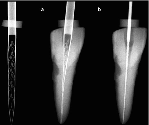
Fig. 11.2
SAF compressed into a narrow canal. Left: the SAF in its relaxed form. (a) The same SAF inserted into a narrow canal, which was prepared with a # 20 K file. (b) A #20 K file that fits into the same canal
The RDT Handpiece Head
The RDT handpiece head (Fig. 11.3) has a dual mechanical function. It transforms the rotation of the micromotor into a trans-line in-and-out vibration with an amplitude of 0.4 mm and contains a clutch mechanism that allows the SAF to rotate slowly when not engaged in the canal but that completely stops the rotation once the file is engaged with the canal walls. The micromotor is operated at 5,000 rpm, which results in 5,000 vibrations/min, and the operator uses pecking motions when using the SAF. Free rotation of the file should occur at the outbound portion of every pecking stroke, when the SAF is disengaged from the canal walls. When the SAF enters the canal during the inbound pecking motion, it should do so at random, with different circular positions, thus ensuring uniform treatment of the canal walls [53–56, 68, 73, 74, 95]. This random circular position also allows the asymmetrical tip of the file to negotiate curvatures that may be found in the root canal. RDT heads may be adapted to a large variety of endodontic motors (Fig. 11.3).
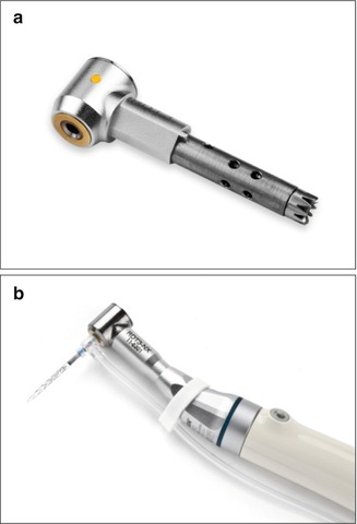
Fig. 11.3
RDT handpiece heads. (a) RDT3 handpiece head that may fit into various handpieces. (b) RDT3-NX handpiece head attached to an X-smart endomotor through a 1:1 NSK gear/adaptor
EndoStation/VATEA Irrigation Pumps
The SAF is provided with a freely rotating hub to which a polyethylene tube is connected (Fig. 11.4), thus allowing the irrigant to flow through the hollow file into the root canal. The irrigant is delivered into the tube by either EndoStation or VATEA irrigation pumps (Fig. 11.5).
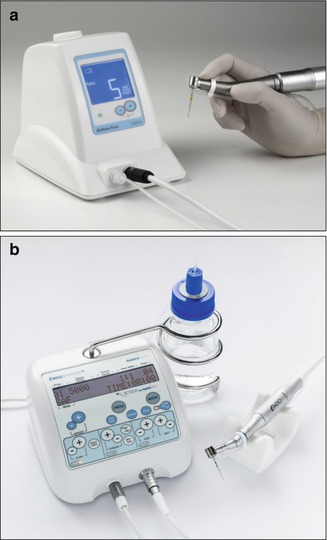
Fig. 11.4
Rotating hub on the SAF for connecting the irrigation tube. The SAF is equipped with a rotating hub that allows it to attach to the irrigation tube, which allows the irrigant to flow from the irrigation pump to the hollow file
Fig. 11.5
EndoStation and a VATEA pump. (a) A VATEA peristaltic pump with irrigant container within the unit. (b) EndoStation is an all-in-one endodontic motor that can be operated in either the ASF mode with irrigation using a handpiece with an RDT head or in rotary mode or reciprocating modes using a regular E-type handpiece. The built-in peristaltic pump draws the irrigant from the external bottle container
The VATEA is a self-contained pump that has a built-in irrigant reservoir of 500 mL and is powered by a rechargeable battery (Fig. 11.1a). The EndoStation is a compound all-in-one machine that can be operated in either rotary or reciprocating file modes, using a regular handpiece, or in the SAF mode, which enables continuous irrigation when using a special separate handpiece with an RDT head. The irrigant container of the EndoStation is an external bottle from which a peristaltic pump draws the irrigant into the tube and into the attached file (Fig. 11.5b).
Either irrigation pump delivers the irrigant at an adjustable flow rate of 1–10 mL/min. Because the file is built as a lattice-walled cylinder, no pressure is generated within the file: any small pressure that is generated by the pump to deliver the irrigant through the tube is eliminated when the irrigant enters the file.
Minimally Invasive Shaping and Cleaning
The concept of minimally invasive shaping and cleaning uses a different method of achieving the same aims as the conventional, traditional shaping and cleaning procedures. Conventional shaping and cleaning, which uses rotary files, involves (a) the removal of large amounts of sound dentin in attempt to include as much as possible the canal wall within the preparation and to allow effective irrigation at the apical end of the canal and (b) the creation of unnoticeable micro-cracks in the remaining dentin by the rotary files [3, 8, 13, 37, 46, 85, 102]. Both these damaging effects were either accepted so far or ignored, as there was no other effective means to thoroughly clean the root canal.
The minimally invasive concept is aimed at achieving the effective cleaning of a root canal by (a) removing a uniform thin layer of dentin around the entire root canal without the unnecessary excessive removal of sound dentin and without causing micro-cracks and (b) providing a continuous flow of fresh, fully active irrigant that is applied with a scrubbing motion of the walls, all the way to the apical part of the canal.
Conventional shaping procedures involve machining the root canal into a desired shape, with either a sequence of rotary instruments or one reciprocating tool. Such process is used (a) to enable irrigation in the apical part of the canal and (b) to facilitate obturation by using a master cone that has the shape of the machined canal. If the canal is straight and narrow with a round cross section, this concept may work well as it may allow the removal of all the inner layers of dentin with anything that was attached to it, be it pulp tissue or bacterial biofilm. The debris are carried coronally by the flutes or compacted into the flutes, and the subsequent irrigation may remove the leftover debris from the canal.
Nevertheless, if this simplistic view of the process is applied to all canals, it may often be considered as treating imaginary canals while ignoring the 3D reality of root canals. MicroCT studies have shown that in oval and curved canals, rotary files fail to remove the inner layer of dentin from all around the canal wall [66, 71]. Furthermore, the discrepancy between the size of the tip of many rotary files (i.e., #25) and the known dimensions and shape of the apical parts of root canals led to the suggestion that a larger apical preparation should be used to include all the apical canal surfaces within the perimeter of the instrumented canal [7, 15, 72]. A larger apical preparation may lead to a further unnecessary removal of sound dentin [44, 52]. All these are avoided when using the minimally invasive concept.
Mode of Irrigation by the SAF System
Positive Pressure Irrigation
The delivery of the irrigant to the apical part of the canal has been traditionally achieved using syringe and needle irrigation [35, 72, 93]. This mode of irrigation applies positive pressure to deliver the irrigant and has several limitations. The irrigant cannot be delivered further than 1–2 mm beyond the tip of the needle; thus, effective irrigation requires the tip of the needle to be 1–2 mm from the working length [10, 16]. The application of positive pressure close to the apical foramen involves the potential risk of pushing the irrigant beyond the apex, commonly termed a “sodium hypochlorite accident” [35]. Consequently, many operators avoid inserting a needle up to the required length, thus compromising the efficacy of the irrigation of the apical cul-de-sac area.
Sonic and Passive Ultrasonic Irrigation
Sonic and passive ultrasonic irrigations are designed to induce agitation or streaming movements of the irrigant to increase the efficiency of its action [18, 47, 48]. Sonic irrigation operates at a low frequency (1–6 kHz) and high amplitude and generates small shear stresses, which have been shown to be efficient for root canal debridement. Studies reported that the sonic instruments may contribute to the cleanliness of the canals but can leave residual debris attached to the canal walls in hard-to-reach areas of long oval canals, isthmuses, and recesses.
Passive ultrasonic irrigation is the use of a smooth metal file that vibrates in the canal at an ultrasonic frequency. The vibrating file induces acoustic streaming, which is a very effective cleaning method [48, 93]. Nevertheless, some studies have not supported these findings. To be effective, the file must have free movement in the canal, without making contact with the canal walls. Consequently, this method may be applied effectively only after canal instrumentation and may be ineffective when applied in curved canals in which the file touches the wall at the canal bend. When either sonic or passive ultrasonic irrigations are used, the canal is filled with irrigant using a syringe and needle.
Negative Pressure Irrigation
The above limitations led to the introduction of irrigation systems that use negative pressure to deliver the irrigant to the desired area [16, 79]. The access cavity is continuously flooded with the irrigant, and a small cannula, through which negative pressure is applied, is inserted in proximity to the working length. This causes the continuous flow of the irrigant into the apical part of the canal while the irrigant is aspirated by the small cannula [60, 79]. This irrigation system is applied after the instrumentation of the canal. For a full effect, this method requires an enlargement of the canal to #40/0.04 or #40/0.06 [12, 26], which makes the method useful in straight canals but of limited value in thin, curved canals in which such enlargement may not be safely achieved.
No-Pressure Irrigation
The SAF may be defined as a no-pressure irrigation system that is applied throughout the instrumentation process [53–57]. Once the irrigant enters the SAF, any pressure that may have existed in the tube disappears due to the lattice structure of the file. The irrigant is continuously delivered into the root canal, and the vibrations of the file, combined with the pecking motion applied by the operator, result in the continuous mixing of the irrigant that is present in the root canal with fresh, fully active irrigant. This mode of action raises two questions: (a) will the freshly applied irrigant be able to reach the apical part of the canal and (b) what is the potential of the pecking motion, which is applied to the working length, to push the irrigant beyond the apex?
The setup in Fig. 11.6a was used to answer the first question. The simulated canal in the transparent block was filled with green liquid, representing the irrigant that is present in the canal (Fig. 11.6b). The SAF was operated with vibrations and pecking motions. At a given time, a red liquid, representing fresh, fully active sodium hypochlorite, was injected into the tube, and the time required for the apical part of the canal to turn completely red was measured. The total replacement of the irrigant in the apical section occurred within 30 s (Fig. 11.6c). When using the SAF system for 4 min, as required by the manufacturer’s instructions, the sodium hypochlorite in the apical part of the canal is continuously replaced with a fresh, fully active solution at least 8 times.
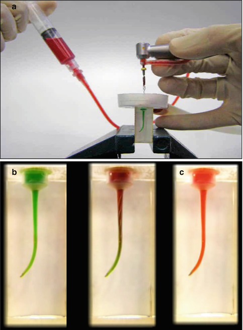
Fig. 11.6
Measuring the time needed for the replacement of the irrigant in the apical part of a simulated canal. A simulated canal was filled with a green liquid, and the SAF was used in this canal. At a given time point, a red liquid was fed into the irrigation tube, and the time required for the liquid in the apical part of the canal to turn red was measured. (a) The setup. (b) Before SAF operation; (c) 30 s after SAF operation. The red liquid represented fresh, fully active sodium hypochlorite. During 4 min of SAF operation, the full replacement of the irrigant at the apical part with fresh, active irrigant occurred eight times
The setup in Fig. 11.7 was used to answer the second question. The tooth was mounted at the bottom of a plastic container with its tip protruding below the container. The canal was prepared to a working length with a #20 K file, and the patency of the apical foramen was verified by passing a #15 K file through it (Fig. 11.7a). The SAF was used in the canal for 4 min with continuous irrigation, and the apical foramen was visually checked for any liquid passage. No liquid passed through the apical foramen throughout the procedure (Fig. 11.7b). When syringe and needle irrigation was applied in the same canal immediately after the SAF, keeping the needle at approximately 12 mm from WL, the liquid passed freely beyond the apex (Fig. 11.7c).
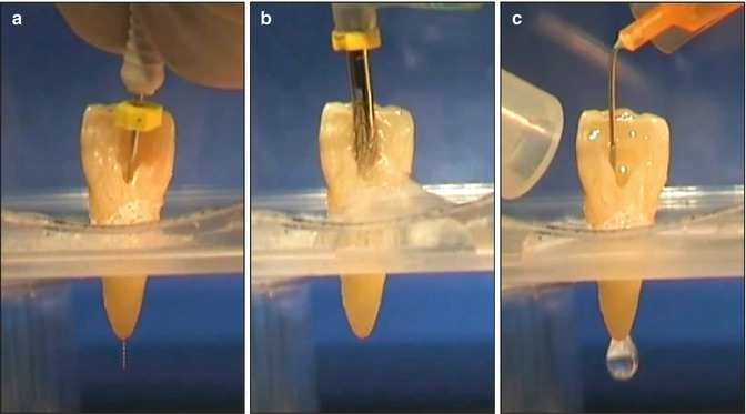
Fig. 11.7
The SAF system vs. syringe and needle irrigation. The tooth was prepared with a #15 K file, which passed through the apical foramen (a) and with a #20 K file to a working length of 1 mm short of the apical foramen. The SAF was used in the canal for 4 min with continuous irrigation (b). No irrigant passed through the apical foramen. (c) A short needle was inserted into the canal to a distance of 12 mm from the apical foramen. The needle was free in the canal and did not touch its walls. When irrigated with this needle, a flow of irrigant traveled through the apex, even though the needle was at a distance from the apex and was free in the canal
Why did the pecking motion not cause liquid extrusion? Why did the syringe and needle cause a free flow of irrigant beyond the apex? Fluid mechanics analyses provide the answers to these questions. Even with a much larger apical foramen with a diameter of 0.35 mm, the liquid is contained in the canal by surface tension. The bursting pressure needed to break this surface tension is 832 Pa. The hydrostatic pressure of a 20 mm column of water is 195 Pa, and the stagnating pressure, caused by 5,000 vibrations per min within the liquid, is 196 Pa. The piston pressure caused by the SAF pecking motion is only 3 Pa. The total pressure in the root canal (394 Pa) is not large enough to reach the bursting pressure, and therefore the liquid remained in the canal [39].
The reason for such a low piston pressure is due to the shape of the apical motion of the SAF (Fig. 11.8). Even in the extreme case of a diameter of 0.2 mm in the apical part of the canal (created by a #20 K file), the fully compressed tip of the SAF has a cross section in the shape of a rectangle of 0.16 by 0.12 mm (Fig. 11.8). This leaves 38 % of the canal cross section open for the backflow of irrigant; thus, the potential piston is ineffective [39].
Fig. 11.8
The tip of the SAF within a canal prepared with a # 20 file. A schematic presentation of the tip of a SAF (rectangle) when inserted into a canal, which was prepared with a #20 K file (circle). Thirty-eight percent of the cross section of the canal is free for backflow. This explains why the SAF is not pushing debris or irrigant through the apical foramen, as presented in Fig. 11.6 (Adapted from Hof et al. [39])
When calculating the pressures caused by syringe and needle irrigation in a canal similar to the one above and keeping the needle in a position in which 38 % of the canal cross section is free for backflow, the syringe and needle create a pressure of more than 1,270 Pa. Such a pressure is generated by the flow of the liquid, even though the needle is not tightly fitted to the canal walls. The total pressure in the canal will reach in this case 1,465 Pa, which is above the eruption pressure and allows the free passage of liquid [39].
The above experiment (Fig. 11.7) was completed in a canal with an open apical foramen with only air surrounding the apex. One may assume that if no liquid passed through the apex during the operation of the SAF system, even in such conditions, the chance that the irrigant will be pushed beyond the apex under clinical conditions, in which the tissues surround the apex, is low.
In this context, when a #20 hand file is moved toward the apex in a tight canal with a diameter of 0.2 mm, the calculated piston pressure may reach the range of hydraulic pressure: 199,700 Pa. This may explain some of the postoperative pain that patients often experience because such pressures are likely to push small volumes of irrigant and/or debris beyond the apical foramen [39].
Mode of Action of Sodium Hypochlorite
As an irrigant, sodium hypochlorite is used (a) to dissolve vital or necrotic pulp tissue that remained in the recesses of the canal after instrumentation and (b) to kill bacteria that may be present in the canal. However, during this process, sodium hypochlorite is gradually inactivated [14, 19, 34].
When pulp tissue is inserted into a test tube containing sodium hypochlorite, sodium hypochlorite quickly dissolves the tissue [75, 96]. In such conditions, the volume of sodium hypochlorite is infinitely larger than that of the pulp tissue, and the inactivation of the solution may not be noticeable. However, in vivo, in the presence of inflammatory exudate, pulp tissue, and microbial remnants, the action of sodium hypochlorite on such substances may consume, weaken, and inactivate sodium hypochlorite [35].
When placed in a root canal, the volume of the sodium hypochlorite is rather limited (~10 μL in the maxillary central incisors), and when pulp tissue or bacteria are present, sodium hypochlorite may be quickly consumed and inactivated. Therefore, simple flooding the canal with sodium hypochlorite during the procedure may be ineffective. Frequent replacement of the irrigant is commonly suggested to maintain the desired activity [6, 35]. When a syringe and needle irrigation is applied, fresh, fully active sodium hypochlorite may be present during the irrigation process, but only up to 2 mm from the distance at which the needle can be inserted. This implies that as long as the needle cannot be safely inserted to WL, no fully active sodium hypochlorite will be present at the apical part of the canal [64]. Any amount of sodium hypochlorite that seeps into this area will be readily inactivated. Thus during traditional endodontic procedures, with intermittent irrigation, the total time that fully active sodium hypochlorite is present at the apical part of the canal is limited.
When negative pressure irrigation is considered, the size of the canal during the instrumentation process is also a limiting factor. Only when the apical part is sufficiently enlarged and the small cannula is inserted to WL can the fully active sodium hypochlorite reach this area.
Mode of Action of EDTA
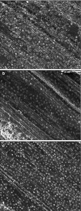
EDTA is often used in endodontic treatment protocols. Some use it to soften the dentin walls of the canal to facilitate instrumentation, while others use it at later stages of the cleaning process to remove the smear layer before disinfection and/or obturation of the root canal. For decalcification of dentin by EDTA, the dentin must first be exposed to sodium hypochlorite [6, 31, 33, 61]. Therefore, in areas of the canal that were not effectively exposed to active sodium hypochlorite, the effect of EDTA may be limited. As any mechanical device, the SAF generates a smear layer [54]. Nevertheless, the subsequent use of EDTA and its activation by the vibrations of the SAF effectively remove the smear layer, even in the apical cul-de-sac area. The frequent appearance of lateral canals in SAF-treated cases (Fig. 11.9) may be the result of the removal of the smear layer plugs that otherwise block the lateral canal entrance [83].
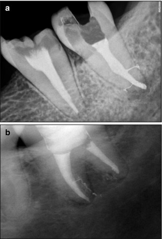
Fig. 11.9
Lateral canals in SAF-treated clinical cases. Lateral canals frequently appear when SAF-treated cases are obturated. (a) Courtesy of Dr. Ajinkia Pawar, Mumbai, India; (b) Adapted from Solomonov [82]
Mode of Cleaning with the SAF System
When the SAF system is used, the process of delivering fresh, fully active sodium hypochlorite is continuous. The SAF protocol requires a glide path that allows the compressed SAF to reach WL at the beginning stages of the procedure. This is different from other instrumentation concepts in which reaching WL represents the end of the procedure. The SAF system is then used for 4 min using pecking motions that reach the WL with a simultaneous continuous replenishing flow of fresh, fully active sodium hypochlorite. This may explain the effective cleaning of the apical part of the canal [2, 54, 55, 101] and the cleaning of the canal’s recesses and fins [23, 45].
Another important cleaning feature of the SAF system is the scrubbing of the canal walls. If pulp tissue or a bacterial biofilm is left in the canal, sodium hypochlorite is commonly expected to dissolve them. However, one should consider the volume and three-dimensional structure of these substances. When the outer layer of the target material is attacked, the inner layers may still be protected from the actions of the sodium hypochlorite. Furthermore, when attacking the outer layers, sodium hypochlorite is inactivated and becomes less potent. The deeper the fin or recess, the more difficult it is to simply dissolve the pulp tissue or biofilm that it may contain.
If the pulp tissue or bacterial biofilm were loosely attached to the canal wall, they could potentially be detached by the flow of irrigant. However, both substances are closely and firmly attached to the canal wall (Fig. 11.10) [59]. Direct mechanical action is often required to remove them from the canal wall [57].
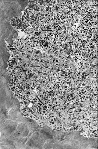
Fig. 11.10
A bacterial biofilm tightly attached to the root canal wall. The mesial root of a mandibular molar was clinically treated, resulting in a satisfactory radiographic result. The apical tip of the root was removed surgically after the procedure and subjected to transmission electron microscopy. The intact biofilm that remained in the isthmus was tightly attached to the dentin wall and was not affected by the copious irrigation with sodium hypochlorite used during the endodontic treatment (Adapted from Nair et al. [59]). BA Bacteria, D Dentin
The SAF consists of a metal mesh, which closely adapts around the canal walls, even in oval canals. Continuous movements of this metal mesh over the surface have a scrubbing effect, which is a more effective method of cleaning (Fig. 11.11).
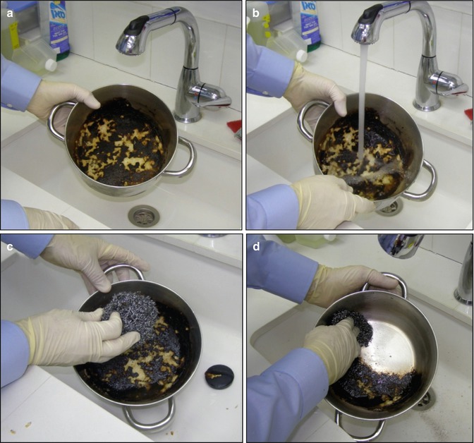
Fig. 11.11
Irrigation vs. scrubbing. An illustration of the efficacy of cleaning by scrubbing. (a) Burnt forage on the bottom of the pot represents the bacterial biofilm or pulp tissue that is tightly attached to the canal walls. (b) Irrigation alone, with no mechanical action, is unlikely to remove such bound material. (c) A metal scrubbing cushion, representing the SAF, is much more effective in cleaning off a tightly bound material (d)
This dual cleaning action of the SAF system, continuous replacement of fresh, fully active sodium hypochlorite, all the way to WL throughout the procedure, and the continuous scrubbing of the canal walls may explain the unique cleaning efficacy of the SAF system [54, 56, 57].
When using the SAF system, EDTA may be applied in the canal with a syringe and needle and then agitated for 30 s by the SAF with the irrigation pump turned off. Alternatively, the pump may be turned off and EDTA applied through a special “y” connector that is attached to the irrigation tube close to its connector to the SAF (Fig. 11.12). In such a case, the continuous flow of EDTA is manually controlled by the person holding the syringe.
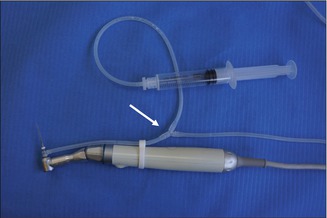
Fig. 11.12
“Y” connector with a syringe containing EDTA. A “Y” connector in the irrigation tube (arrow) allows for the attachment of a syringe containing EDTA that may be applied into the SAF during its operation while the irrigation pump is turned off. The tube connecting the “y” connector to the EDTA syringe may be longer, to allow comfortable operation by the dental assistant
Cleaning Efficacy of the SAF System
The ultimate tool for evaluating the cleaning efficacy of a root canal is scanning electron microscopy (SEM). Many studies have used this tool to evaluate the cleaning of a root canal [4, 17, 28, 40, 51, 62, 70, 94].
In the majority of these studies, while the coronal and middle parts of the root canal may be effectively cleaned by rotary files and syringe and needle irrigation, the apical part of the canal, with its cul-de-sac shape, presented a greater challenge. In most of these studies, the apical part of the canal contained large amounts of debris and was covered with a smear layer, even after EDTA irrigation [4, 17, 28, 40, 51, 62, 70, 94].
Stay updated, free dental videos. Join our Telegram channel
VIDEdental - Online dental courses


