The success of orthognathic surgery depends not only on the technical aspects of the operation but, also, to a larger extent, on the formulation of a precise surgical plan. Over the last 50 years, while there have been significant improvements in the technical aspects of surgery, that is, rigid fixation, resorbable materials, distraction osteogenesis, minimally invasive approaches, among others, the planning methods have mostly remained unchanged. Unfortunately, there are a number of problems with the current planning methods. Each one of these problems can result in a bad surgical outcome. In isolation, these problems may seem trivial, but, when added together, the results can be devastating.
Problems with Traditional Planning Methods for Planning Orthognathic Surgery
In orthognathic surgery, surgical planning involves a series of logical steps. These steps include (1) data gathering, (2) diagnosis and quantification of the condition, (3) establishment of a preliminary surgical plan, (4) surgical simulation, (5) establishment of the final surgical plan, and (6) transfer of the plan to the patient.
The traditional planning methods for orthognathic surgery follow a basic sequence. Data is gathered from a multitude of different sources. These include the physical examination, medical photographs, x-rays (e.g., cephalogram, orthopantomogram), computed tomography (CT) scans, and mounted stone dental models. Each of these sources provides a portion of the whole data set that is needed for successful planning. In practice, a surgeon evaluates each of these data sources in a sequential manner and creates a complete three-dimensional (3D) mental picture of the condition.
The next step in the planning process is the diagnosis and quantification of deformity. In orthognathic surgery, an important part of this process is the cephalometric analysis. This is done by tracing the bony outlines and soft tissue profiles of a cephalogram. The angles, distances, and relationships are measured between selected landmarks. These measurements help surgeons to diagnose and quantify the problems.
After the surgeon has formulated the diagnosis, in the third step, he or she develops a preliminary plan. In many instances, the surgeon will also develop alternative plans. To test the feasibility of the preliminary plan(s), the surgeon simulates the planned surgery. In orthognathic surgery, this is accomplished by completing prediction tracings and dental model surgery. Prediction tracings are made by tracing the silhouette of the facial bones from a two-dimensional cephalogram onto a piece of acetate paper. These tracings are then cut and moved to evaluate possible outcomes. Dental model surgery is done on stone dental models that have been mounted on an articulator. An articulator is a mechanical device that reproduces the positions of the mandible in relation to the maxilla. Dental model surgery is performed by physically cutting the models and moving them to the desired position.
After the simulation has been completed, in the fourth step, the surgeon formulates the final surgical plan. The final step in the planning process is to transfer the surgical plan to the patient at the time of surgery. In orthognathic surgery, the surgical plan is transferred to the patient using surgical splints and selected measurements. The surgical splints are plastic wafers that are placed between the teeth at the time of surgery. They relate a cut jaw segment to an uncut one. Prior to surgery, the splints are fabricated on the stone dental models on which the surgery has been simulated.
There are a number of problems with the traditional planning system. These include:
- 1
The various data sources use different coordinate systems. The physical examination and the medical photographs are taken with the patient’s head oriented to the neutral head posture (NHP). The cephalogram is oriented to the Frankfurt horizontal (FH) plane, and the articulated dental models are oriented to the axis-orbital plane. On average, these planes differ from each other by 8 degrees. Currently, most surgeons are unaware of this problem and fail to account for these differences. This problem alone can be responsible for a 15% difference in maxillary projection between planned and actual outcomes.
- 2
With the traditional method, surgeons are never able to visualize the whole data set in three dimensions. As stated above, the surgeons have to create this picture in their minds. This causes problems in communicating with the other members of the treatment team. As would be expected, it is impossible to ensure that all involved have the same picture.
- 3
The cephalometric analysis is in two dimensions. Therefore, it only measures structures in a single plane. It may be appropriate for patients with symmetrical deformities but is grossly inadequate for patients with asymmetrical conditions. It has been calculated that 34% of patients with dentofacial deformities have asymmetrical conditions.
- 4
The orientation of dental models mounted on an articulator is often inaccurate. The occlusal plane inclination of models mounted on a semiadjustable articulator is, on average, 8 degrees too steep. In addition, there are design flaws in the current devices used to orient the dental models on an articulator (i.e., the facebow). A patient can easily tilt the facebow during the registration process, creating an inaccurate recording of the occlusal cant (roll of the upper jaw). An inaccurate initial model position will always create an inaccurate plan.
- 5
The stone dental models do not depict the surrounding bones. Dental model surgery is done for two purposes. The first is to establish the occlusion and the second is to reorient the models to ensure that the bones are placed in the ideal position at surgery. Because stone dental models do not depict the surrounding bones, the surgeon is unable to visualize the effects of the model position on the facial skeleton. Therefore, the attainment of the ideal bone position becomes a random event. In our opinion, this problem is the largest source of error.
- 6
Prediction tracing and model surgery are two separate processes that are inaccurate and time consuming. Currently, an experienced surgeon spends 3 to 5 hours completing these steps.
- 7
Some surgeons use CT-based rapid prototyping models to plan complex surgeries. The drawbacks to these rapid prototyping models are that they are costly (models range in price from $400 to $2500), they are unable to simulate different iterations of a given plan on a single model (i.e., once the model is cut, the cut cannot be undone), and they fail to render the teeth with the precision necessary for surgical planning.
- 8
The fabrication of splints is time consuming. A busy surgeon performs several of these operations per week, and many patients require two splints. The fabrication of each splint may take an additional hour.
Computer-Aided Surgical Simulation (CASS) for Orthognathic Surgery
It is clear that many compromised surgical outcomes are the result of deficient planning. The need to improve the traditional surgical planning methods has led our group to develop a 3D computer-aided surgical simulation (CASS) system to plan craniomaxillofacial surgeries. The ultimate goal of CASS is to completely eliminate the problems associated with the traditional surgical planning methods. Using this CASS system, all the patient information (clinical examination, clinical photographs, cephalogram, dental models, and CT images) is merged into a single data set that is oriented in a unique 3D coordinate system, the NHP. In addition, the patient’s anatomic structures (the bones, teeth, and soft tissues) are rendered three dimensionally and can be visualized from any arbitrary viewpoint. CASS also eliminates the inaccurate facebow transfer by digitally incorporating dental models into the bone models using fiducial markers. Furthermore, the prediction tracing, dental model surgery, and CT model surgery are merged into a single virtual process. Surgeons can perform “virtual surgery” and create a 3D prediction of the patient’s surgical outcomes, as if they are performing surgery in the operating room. Finally, the surgical splints and templates are designed and fabricated in the computer using computer-aided design and computer-aided manufacturing (CAD/CAM) techniques.
Our CASS system incorporates three distinctive features and innovations: (1) multiple imaging modalities are used to create an accurate model of the craniofacial skeleton, (2) special techniques are employed to orient the computerized bone model in the NHP, and (3) CAD/CAM techniques are used to fabricate accurate surgical splints and templates to transfer the surgical plan to the operating room. We have used this system in maxillofacial surgery, craniofacial surgery, trauma, and distraction osteogenesis. In addition, we have also documented the clinical feasibility, the accuracy, and the cost-effectiveness of this system. Our CASS planning protocol for orthognathic surgery is presented step-by-step as follows.
Step 1: Physical Examination and Anthropometric Measurements
A complete physical examination and anthropometric measurements are essential in the clinical decision-making process. These approaches are the only way to obtain information regarding the quality of the tissues and their dynamic deformation with function (see Pearls and Pitfalls section for details). During the physical examination, critical areas of concern should be head orientation, incisor show at rest and with smiling, midline deviations, and any dystopia.
Step 2: Creation of a Computerized Composite Skull Model
A composite skull model is a computerized 3D model that is an accurate rendition of the soft tissues, bones, and teeth. Although CT scans have been successfully used to visualize the soft tissues and bones, they have not been used for surgical simulation, because CT does not render the teeth with the accuracy that is necessary for surgical planning. To solve this problem, the authors developed a composite skull model by incorporating accurate digital dental models into a 3D CT model of the face. This was done by merging two separate digital data sets: the digital dental models and the 3D CT. The separate data sets are merged by using fiducial markers (common reference points). The fiducial markers used in this protocol are spheres that are part of a specially designed facebow (Medical Modeling Inc., Golden, Colo.). The facebow is attached to a bite registration that is placed between the patient’s maxillary and mandibular dental arches and between the stone models before they are scanned ( Fig. 74-1 ).

There are four steps in the process of creating a composite skull model: (1) create a bite registration, (2) create 3D CT models of the craniomaxillofacial skeleton, (3) create a set of digital dental models, and (4) merge the digital dental models into the patient’s CT models.
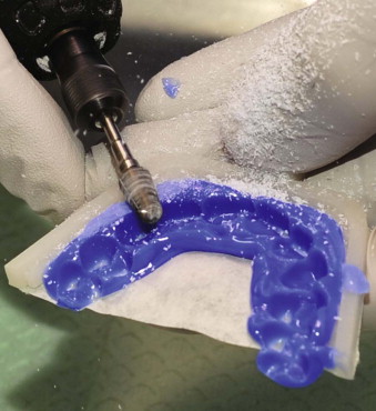
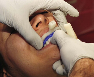
The first step is to fabricate a bite registration. The main purpose of the bite registration is to relate the fiducial markers to the teeth, but it is also used to maintain the mandible in centric relation (CR) during scanning. For this purpose, a special bite fork has been designed that is placed buccally to the teeth. It is composed of a plastic frame with a layer of paper that holds the bite registration material ( Fig. 74-2, A ). The bite fork has an anterior attachment for the removable facebow ( Fig. 74-2, B ). It is necessary to use a dimensionally stable, rigid, bite registration material, for instance, LuxaBite (Chemisch-Pharmazeutische Fabrik GmbH, Hamburg, Germany) to prevent the deformation and distortion of the bite registration. This material sets rigidly and can be carved with a bur ( Fig. 74-3 ). In order to make the actual registration, the material is first placed over the paper underside of the bite fork, and an impression is taken of occlusal surfaces of the maxillary teeth. After the material has hardened and the paper backing is removed, additional material is added on the mandibular side of the fork. The mandibular bite registration is captured in CR ( Fig. 74-4 ). Once the bite registration is created, it is attached to the facebow (see Fig. 74-1, A ).

The second step is to create 3D CT models of the craniomaxillofacial skeleton. A CT scan of the patient’s craniofacial skeleton is obtained with the bite-registration–facebow assembly in place (see Fig. 74-1, B ). The CT scan is completed using the standard scanning algorithm, matrix of 512 × 512 at 0.625-mm slice thickness, 25-cm or less field-of-view (FOV), 0-degree gantry tilt, and 1 : 1 pitch. Once the CT scan is obtained, it is segmented, and three separate but correlated computer models are generated: a midface, a mandibular, and a fiducial-marker model (see Fig. 74-1, C ).
The third step is to create a set of digital dental models. First, dental impressions are taken of the upper and lower teeth. The impressions are poured with a special dimensionally stable and laser-friendly stone, for instance, Diamond Die (Hi-Tec Dental Products Inc, Greenback, Tenn.). The stone dental models are then placed on the bite-registration–facebow assembly and mounted on a custom jig that keeps the relationship between the models unaltered during scanning. The models are then scanned using a surface laser scanner (resolution: 0.1 mm or higher). An alternative is to scan the models with a micro-CT scanner (resolution: 7 µm to 75 µm) (see Fig. 74-1, D ). After scanning, the data is segmented generating three separate but correlated computer models: an upper digital dental, a lower digital dental, and a fiducial-marker model (see Fig. 74-1, E ).
The final step is to merge the digital dental models into the patient’s CT models. After the 3D CT models and the digital dental models are obtained, the teeth on the 3D CT model are removed, leaving the fiducial markers in place. The maxillary and the mandibular digital dental models with their corresponding fiducial markers are imported into the CT skull model. By aligning the fiducial markers, the digital dental models are incorporated into the 3D CT skull model. The fiducial markers are then marked hidden. This results in a computerized composite skull model that simultaneously displays an accurate rendition of the bones and the teeth (see Fig. 74-1, F ).
Step 3: Reorientation of the Composite Skull Model to the Neutral Head Posture
An important prerequisite for accurate planning is to orient the 3D composite skull model to the NHP in the computer. In order to capture a patient’s NHP, a digital orientation sensor is attached to the facebow that was used to create a composite skull model. With the patient in the NHP, the pitch, roll, and yaw of the face are recorded.
The recorded information is then used to reorient the composite skull model in the computer. A digital replica (CAD model) of the digital orientation sensor–face-bow assembly is registered (i.e., superimposed) to the fiducial markers of the composite skull model, and the two objects are attached to each other. Afterward, the recorded pitch, roll, and yaw are applied to the center of the CAD model of the digital orientation sensor, reorienting the composite skull model to the NHP ( Fig. 74-5 ).

Step 4: Analysis and Quantification of the Deformity
In CASS, the analysis and quantification of the deformity is completed in both two and three dimensions. Initially, to facilitate this task, a unique 3D reference system is constructed for the composite skull model. The reference system has its origin at the soft tissue nasion and consists of three orthogonal planes: sagittal, coronal, and axial. In the reference system, the sagittal plane is the patient’s true midsagittal plane. Once the composite model is positioned in the 3D reference system, the user digitizes the selected cephalometric landmarks and chooses the desired analysis.
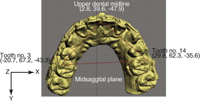
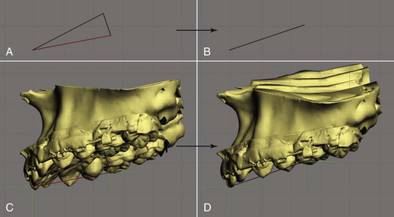
In the 3D analysis, we first examine the anatomic structures for symmetry. To examine the symmetry of the maxilla, we have developed a method based on the work of Grayson. In this method, a triangular spline is created on the maxillary dentition by digitizing three landmarks: the maxillary dental midline and two corresponding landmarks on the right and left molars (usually the mesiobuccal cusp of the maxillary right and left first molars, Fig. 74-6 ). The software reads the x, y, and z coordinates of each vertex of the triangle to automatically calculate the pitch, roll, and yaw of the maxilla as well as the maxillary midline deviation. The pitch represents the maxillary occlusal plane inclination, while the roll and yaw represent the occlusal cant and the horizontal rotation. In some instances, because of the difficulty interpreting some 3D data and the unavailability of the 3D normative data, we still use a conventional 2D analysis, in which all the 3D landmarks are projected onto the midsagittal plane. Bilateral landmarks are averaged in the anteroposterior and vertical axes. In this mode, we make decisions regarding anteroposterior projection, vertical position, and inclinations of the occlusal plane and mandibular plane (pitch).
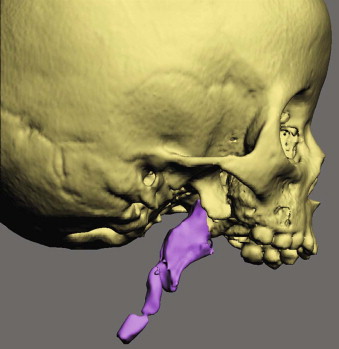
In addition to the 2D and 3D measurements, the CASS system is also able to perform volumetric measurements. These measurements have proven to be useful in the quantification of airway and orbital volumes ( Fig. 74-7 ).
Step 5: Simulation of Surgery in the Computer
Any type of osteotomy can be simulated in this CASS system, for instance, Le Fort I, sagittal split, and genioplasty, among others. After the bones are osteotomized, the user can move and rotate the bony segments to the desired position. In patients requiring bimaxillary surgery, the maxillary surgery is usually simulated first. The maxilla is first repositioned to symmetry. The triangular spline used to quantify the maxillary asymmetry is “attached” to the maxilla so that any movement of the triangle is automatically transferred to the maxilla. The software reads the x, y, and z coordinates of the triangle vertices and calculates the discrepancy between right and left. It then automatically moves the upper dental midline to the midsagittal plane, and rotates the triangle to symmetry (0 degrees of roll, 0 degrees of yaw, and balanced pitch, Fig. 74-8 ). This triangular method works especially well when the dental arch itself is symmetrical. If the dental arch is asymmetrical, the user’s intervention may be required to move/rotate the maxilla to the most balanced position. After the asymmetry of the maxilla is corrected, the maxillary pitch (occlusal plane inclination) is adjusted, and the maxilla is moved anteroposteriorly and superoinferiorly to the desired position based on the cephalometric analysis and clinical measurements.
After the maxilla is placed in its final position, the distal segment of the mandible is moved to maximal intercuspation (MI). Unfortunately, in the computer, the establishment of MI is difficult. It is almost impossible to be certain that what is seen in the computer truly represents the best possible alignment. To ensure that the digital final occlusion is at its correct MI, the stone models are first physically positioned in MI (final occlusion) and then scanned in this position. This second set of digital models is used to guide the precise placement of the distal mandible into MI. Once the distal segment is in position, the proximal segments of the mandible are aligned. If necessary, a genioplasty can also be simulated.
In some instances, the repositioning of the osteotomized segments is not sufficient to recreate facial symmetry. This is due to the fact that in many patients with facial asymmetries, the bones are not only asymmetrically displaced but also differ in size and shape from one side to the other. Therefore, it is necessary to reevaluate the symmetry after the simulation of the jaw movements. To help with this, a mirror-imaging tool is used. With it, one half of the face is selected, copied, mirror-imaged (flipped), and superimposed on the contralateral side ( Fig. 74-9 ). The differences between the two sides are then calculated using a Boolean operation. Based on this information, the surgeon may decide to add volume (grafting), remove volume (ostectomy), or adjust the position of the segments (camouflage).

Step 6: Transfer of the Computerized Plan to the Patient
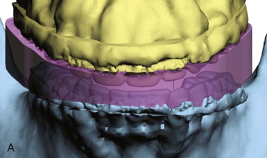
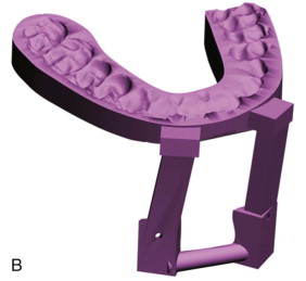
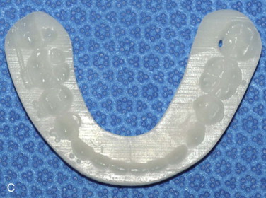
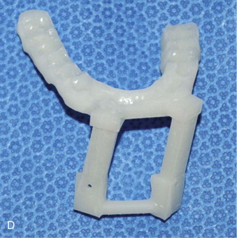
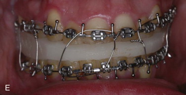
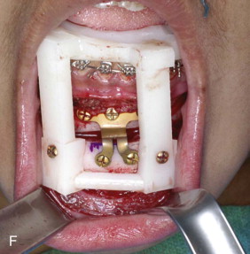
After the surgical plan is finalized, it is necessary to transfer the plan to the patient at the time of the surgery. Surgical dental splints or surgical templates can be created for this purpose. Surgical dental splints are used to reposition dentate bony segments, while surgical templates are used to reposition nondentate ones. The surgical dental splints are created by inserting a digital wafer between the maxillary and mandibular dental arches. A Boolean operation is then performed, resulting in a digital surgical splint ( Fig. 74-10, A ). The surgical templates record the 3D surface geometry of the area of interest so that they fit on the bone in a unique position ( Fig. 74-10, B ). The system can export the digital splints and templates in “stl” format. These are fabricated using a rapid prototyping machine ( Figs. 74-10, C and D ), and are subsequently used at the time of surgery ( Figs. 74-10, E and F ).
Computer-Aided Surgical Simulation (CASS) for Orthognathic Surgery
It is clear that many compromised surgical outcomes are the result of deficient planning. The need to improve the traditional surgical planning methods has led our group to develop a 3D computer-aided surgical simulation (CASS) system to plan craniomaxillofacial surgeries. The ultimate goal of CASS is to completely eliminate the problems associated with the traditional surgical planning methods. Using this CASS system, all the patient information (clinical examination, clinical photographs, cephalogram, dental models, and CT images) is merged into a single data set that is oriented in a unique 3D coordinate system, the NHP. In addition, the patient’s anatomic structures (the bones, teeth, and soft tissues) are rendered three dimensionally and can be visualized from any arbitrary viewpoint. CASS also eliminates the inaccurate facebow transfer by digitally incorporating dental models into the bone models using fiducial markers. Furthermore, the prediction tracing, dental model surgery, and CT model surgery are merged into a single virtual process. Surgeons can perform “virtual surgery” and create a 3D prediction of the patient’s surgical outcomes, as if they are performing surgery in the operating room. Finally, the surgical splints and templates are designed and fabricated in the computer using computer-aided design and computer-aided manufacturing (CAD/CAM) techniques.
Our CASS system incorporates three distinctive features and innovations: (1) multiple imaging modalities are used to create an accurate model of the craniofacial skeleton, (2) special techniques are employed to orient the computerized bone model in the NHP, and (3) CAD/CAM techniques are used to fabricate accurate surgical splints and templates to transfer the surgical plan to the operating room. We have used this system in maxillofacial surgery, craniofacial surgery, trauma, and distraction osteogenesis. In addition, we have also documented the clinical feasibility, the accuracy, and the cost-effectiveness of this system. Our CASS planning protocol for orthognathic surgery is presented step-by-step as follows.
Step 1: Physical Examination and Anthropometric Measurements
Stay updated, free dental videos. Join our Telegram channel

VIDEdental - Online dental courses


