Material and methods
Forty-eight stainless steel (medical class 316 LVM; Dentos, Daegu, South Korea) and 48 titanium alloy (Ti6Al4V; Dentos) self-threading MSIs (length, 6 mm; diameter, 1.6 mm), of identical design and fabrication, were inserted into 12 male New Zealand white rabbits, 4 to 5 months old and weighing 3.5 to 4.5 kg (Harlan Laboratory, Indianapolis, Ind). The Institutional Animal Care and Use Committee approval was obtained from Indiana University-Purdue University, Indianapolis. The 24 tibias of the 12 rabbits were assigned to 1 of the 4 experimental groups using the random block design outlined in Table I .
| Location | Rabbits 3, 6, 10 | Rabbits 4, 8, 11 | Rabbits 1, 9, 12 | Rabbits 2, 5, 7 | ||||
|---|---|---|---|---|---|---|---|---|
| Left tibia | Right tibia | Left tibia | Right tibia | Left tibia | Right tibia | Left tibia | Right tibia | |
| Removal torque | Histology | Histology | Removal torque | Removal torque | Histology | Histology | Removal torque | |
| 1 (proximal) | SS-NL | SS-L | SS-NL | SS-L | TiA-NL | TiA-L | TiA-NL | TiA-L |
| 2 | TiA-NL | TiA-L | TiA-NL | TiA-L | SS-NL | SS-L | SS-NL | SS-L |
| 3 | SS-L | SS-NL | SS-L | SS-NL | TiA-L | TiA-NL | TiA-L | TiA-NL |
| 4 (distal) | TiA-L | TiA-NL | TiA-L | TiA-NL | SS-L | SS-NL | SS-L | SS-NL |
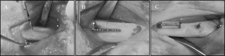
Two stainless steel and 2 titanium alloy MSIs were placed in each tibia ( Fig 1 ), 1 of each type in the proximal portion of the tibia (locations 1 and 2), and 1 of each type in the distal portion (locations 3 and 4), as detailed in Table I . Forty-eight (24 adjacent pairs) implants were immediately loaded with a GAC Sentalloy 3-mm closed-coil spring (Dentsply GAC International, Bohemia, NY) applying a relatively continuous force of 100 g (0.98 N). The force magnitude was verified with a digital force gauge (Lutron Electronics Enterprise, Taipei, Taiwan) during placement and removal. The other 48 MSIs remained unloaded.
Meloxicam (0.2 mg/kg subcutaneously; Boehringer Ingelheim, St Joseph, Mo) was given 40 to 60 minutes before the procedure as an analgesic. A single dose of meloxicam has been shown to have no effects on bone healing adjacent to implant sites. At the time of anesthesia, the animals were induced by acepromazine (0.6 mg/kg) and butorphanol tartrate (0.75 mg/kg). After initial induction, anesthesia was maintained with isoflurane (3.5% at 1.5 L/m) via gas mask. One dose of the broad spectrum antibiotic enrofloxacin at 4 mg per kilogram subcutaneously was given at the time of surgery.
After incision and blunt dissection through skin, fascia, and periosteum, the middiaphyseal portion of the proximal and distal tibia was exposed. The MSI pilot holes were drilled 9 mm apart, each with a new 1.3 mm × 7/10/14-mm increment twist drill at low speed with copious saline-solution irrigation. The MSIs were gently screwed into place by an operator (R.N.B) with an insertion torque screwdriver (DI-5N-RL2; Imada, Northbrook, Ill), until the implant shoulder was level with the bone surface. The peak insertion torque and primary stability were recorded. To assess clinical insertion and removal stabilities, forceps were used to gently move the MSIs, and any MSI that showed mobility greater than 1 mm was deemed a failure. In the loaded groups, the Sentalloy coil springs were applied. To limit tissue ingrowth, they were covered with medical-grade latex-free tubing ( Fig 1 ; Tygon; U.S. Plastic, Lima, Ohio).
To completely cover the implant and the spring, the fascia and the skin were closed in separate layers with resorbable 4.0 Monocryl sutures (Ethicon, San Angelo, Tex), and aluminum foil was wrapped around the tibia to protect the sutures. After surgery, Baytril (4 mg/kg subcutaneously) was administered once daily for 4 days. Meloxicam (0.2 mg/kg subcutaneously) was administered once daily for 2 days. Buprenex (Reckitt Benckiser Pharmaceuticals, Richmond, Va) was used for breakout pain (0.01-0.05 mg/kg subcutaneously, at 8-24 hours) as needed. The animals were checked daily for body temperature, hydration status, activity, food and water consumption, and conditions at the operative site. Alizarin (20 mg/mL) and calcein (10 mg/mL) bone labels were injected at weeks 4 and 5, respectively, after MSI placement to allow dynamic histomorphometry measures. Six weeks after surgery, the animals were euthanized with B-euthanasia 1 mL per 4.5 kilograms intravenously (Merck Animal Health, Summit, NJ).
Immediately after the rabbits were euthanized, 24 stainless steel and 24 titanium alloy (half loaded, half unloaded) MSIs and the surrounding bones were dissected for measuring peak removal torque ( Table I ) with a digital torque gauge (BGI torque gauge; Mark-10, Copiague, NY). The gauge was positioned on the hexagonal implant head, and increasing torque was applied to the point of first “give.” The peak torque registered by the instrument was recorded.
The remaining 48 MSI blocks were dissected free and fixed for 2 weeks in 70% ethanol for histomorphometric analysis. Staining with basic fuchsin was performed according to published procedures. This technique allows for the differentiation of cracks caused by the implant or drilling (stained) from cracks formed during grinding and polishing of the histologic slides (unstained). After staining, the blocks were embedded in methylmethacrylate and sectioned (IsoMet low speed saw; Buehler, Lake Bluff, Ill) along the plane through the length of the implant and parallel to the tibia. Sections were ground and polished to 150 to 170 μm in thickness with an Exakt system (EXAKT Technologies, Oklahoma City, Okla).
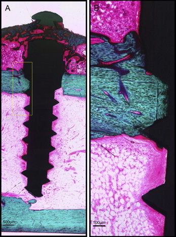
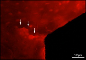
Microdamage was identified under an epifluorescence microscope (Leica Microsystems, Buffalo Grove, Ill) with an excitation wave length of 546 using Osteo II software (Bioquant Image Analysis, Nashville, Tenn) following the same criteria published previously. Cortical bone thickness near the implant was measured under 4× objective magnification in triplicate and averaged. Microdamage was assessed using 10× objective magnification ( Fig 2 ) on both sides (tension and compression for the loaded MSIs; proximal and distal for unloaded MSIs) of all 48 implants. Crack length and MSI implant surface length in bone were measured. The crack density (number of total cracks/implant surface length) and the total microdamage burden per surface length (number of cracks × average crack length/implant surface length) were calculated for each specimen. All measurements were made by the same blinded examiner (B.E.S.). Intrarater reliability was 0.93 for analysis of microcrack parameters and was based on intraclass correlation between 2 blinded measurements with a 2-week interval on 10 randomly selected sections.

After microdamage and bone remodeling rate analyses, the samples were counterstained in light green stain (L1886-25G; Sigma-Aldrich, St Louis, Mo) for 10 minutes to impart a green color selective to bone tissue. Under the bright field of the microscope, the images of the implant and surrounding bone were captured with 4× magnification. Multiple images of each MSI were merged using Image Composite Editor software (Microsoft, Redmond, Wash). The borders of the MSIs were traced, and total bone-to-implant contact length at the midpoint of the vertical axis was measured on the sides of tension and compression ( Fig 3 ). The bone-to-implant contact ratio was calculated using the following formula: bone-to-implant contact ratio = (length of bone in direct contact with implant/total implant length) × 100%.
Statistical analysis
Insertion torque, removal torque, microdamage, and bone-to-implant contact measurements were summarized. Mixed-model analysis of variance (ANOVA) models were used to investigate the differences including the effects of metal (titanium alloy vs stainless steel), loading (loaded vs unloaded), location of implant, and the 2-way interactions between these factors. Comparisons between groups were evaluated with the level of significance set at 0.05 using SAS software (SAS Institute, Cary, NC). Distributions of the data were examined, and no transformations of the measurements (eg, natural logarithm) were necessary to satisfy the ANOVA assumptions. Based on data from a previous study in dogs, with a sample size of 12 rabbits, our study would have 80% power to detect a microdamage difference of 0.7 between the titanium alloy and the stainless steel implants, between loaded and unloaded implants, or between implant locations.
Anchorage management is the key to orthodontic success, but reliance on patient compliance has made it a true challenge. Therefore, the use of miniscrew implants (MSIs) for skeletal anchorage has rapidly spread. MSIs have been successfully used for space closure, intrusion, extrusion, molar uprighting, open-bite closure, and a continuously increasing variety of other anchorage needs. Thus, a better understanding of these devices is essential to facilitate patient care.
Many studies have demonstrated the effectiveness of MSIs. A recent meta-analysis reported success rates of 87.7% and above. This is relatively low considering that dental implant success rates are 95% and higher. Although many factors affect MSI success rates, implant tip breakage during insertion is a serious complication mainly because of the need for surgical removal. As the MSI diameter decreases, it weakens, leading to potential breakage when the insertion or removal torque exceeds the torsional strength. Thus, stainless steel, because it is stronger than the traditional titanium alloy, would reduce breakage.
Stainless steel bone screws have been widely used for fracture fixation. Unlike titanium alloy, stainless steel bone screws tend to develop a fibrous tissue interface between the screw and bone ; this lowers removal torque, leading to easier retrieval. MSIs are generally made of titanium alloys. Titanium is a highly biocompatible material that allows for direct bone contact (osseointegration) between endosseous dental implants and the host bone. However, the high degree of osseointegration required for dental implants is not a requirement for orthodontic MSIs to function as anchorage devices.
Promising results have been reported for stainless steel MSIs used for en-masse space closure. However, properties such as primary stability and bone-healing responses still need to be examined. The former, defined as the mechanical retention at insertion, is quantified by insertion torque. A systematic review suggested that a wide range of insertion torque values can achieve high MSI success rates, but excessive insertion torque might cause detrimental effects such as bone necrosis and increased bone microdamage. Microdamage initiates rapid bone remodeling and healing, but if it accumulates, bone mechanical properties are reduced, thus potentially contributing to MSI failure.
With bone healing after insertion, new bone forms and remodels surrounding the implant. The bone-to-implant contact ratio (implant surface in contact with bone divided by total implant surface) is commonly used to indicate the degree of bone-implant adaptation. As little as 5% of bone-to-implant contact has been shown to successfully resist orthodontic loads. Removal torque is another indicator that reflects bone-to-implant contact and the MSI’s anchorage capability. Clinically, removal torque of titanium alloy MSIs varies from 4 to 16 N-cm, depending on surface treatments. It is speculated that fibrous tissues develop around stainless steel screw threads, leading to reduced bone-to-implant contact and removal torque with increased potential for failure.
Immediate loading of MSIs, which is now common practice, might alter the microdamage healing process and the resulting bone-to-implant contact. The purpose of this study was to evaluate the stability, insertion torque, microdamage burden, bone-to-implant contact, and removal torque of stainless steel and titanium alloy MSIs with or without immediate orthodontic loading. We hypothesized that stainless steel and titanium alloy miniscrews would produce similar values as indicators of mechanical stability, since both were expected to have low degrees of osseointegration.
Material and methods
Forty-eight stainless steel (medical class 316 LVM; Dentos, Daegu, South Korea) and 48 titanium alloy (Ti6Al4V; Dentos) self-threading MSIs (length, 6 mm; diameter, 1.6 mm), of identical design and fabrication, were inserted into 12 male New Zealand white rabbits, 4 to 5 months old and weighing 3.5 to 4.5 kg (Harlan Laboratory, Indianapolis, Ind). The Institutional Animal Care and Use Committee approval was obtained from Indiana University-Purdue University, Indianapolis. The 24 tibias of the 12 rabbits were assigned to 1 of the 4 experimental groups using the random block design outlined in Table I .
| Location | Rabbits 3, 6, 10 | Rabbits 4, 8, 11 | Rabbits 1, 9, 12 | Rabbits 2, 5, 7 | ||||
|---|---|---|---|---|---|---|---|---|
| Left tibia | Right tibia | Left tibia | Right tibia | Left tibia | Right tibia | Left tibia | Right tibia | |
| Removal torque | Histology | Histology | Removal torque | Removal torque | Histology | Histology | Removal torque | |
| 1 (proximal) | SS-NL | SS-L | SS-NL | SS-L | TiA-NL | TiA-L | TiA-NL | TiA-L |
| 2 | TiA-NL | TiA-L | TiA-NL | TiA-L | SS-NL | SS-L | SS-NL | SS-L |
| 3 | SS-L | SS-NL | SS-L | SS-NL | TiA-L | TiA-NL | TiA-L | TiA-NL |
| 4 (distal) | TiA-L | TiA-NL | TiA-L | TiA-NL | SS-L | SS-NL | SS-L | SS-NL |
Two stainless steel and 2 titanium alloy MSIs were placed in each tibia ( Fig 1 ), 1 of each type in the proximal portion of the tibia (locations 1 and 2), and 1 of each type in the distal portion (locations 3 and 4), as detailed in Table I . Forty-eight (24 adjacent pairs) implants were immediately loaded with a GAC Sentalloy 3-mm closed-coil spring (Dentsply GAC International, Bohemia, NY) applying a relatively continuous force of 100 g (0.98 N). The force magnitude was verified with a digital force gauge (Lutron Electronics Enterprise, Taipei, Taiwan) during placement and removal. The other 48 MSIs remained unloaded.

Meloxicam (0.2 mg/kg subcutaneously; Boehringer Ingelheim, St Joseph, Mo) was given 40 to 60 minutes before the procedure as an analgesic. A single dose of meloxicam has been shown to have no effects on bone healing adjacent to implant sites. At the time of anesthesia, the animals were induced by acepromazine (0.6 mg/kg) and butorphanol tartrate (0.75 mg/kg). After initial induction, anesthesia was maintained with isoflurane (3.5% at 1.5 L/m) via gas mask. One dose of the broad spectrum antibiotic enrofloxacin at 4 mg per kilogram subcutaneously was given at the time of surgery.
After incision and blunt dissection through skin, fascia, and periosteum, the middiaphyseal portion of the proximal and distal tibia was exposed. The MSI pilot holes were drilled 9 mm apart, each with a new 1.3 mm × 7/10/14-mm increment twist drill at low speed with copious saline-solution irrigation. The MSIs were gently screwed into place by an operator (R.N.B) with an insertion torque screwdriver (DI-5N-RL2; Imada, Northbrook, Ill), until the implant shoulder was level with the bone surface. The peak insertion torque and primary stability were recorded. To assess clinical insertion and removal stabilities, forceps were used to gently move the MSIs, and any MSI that showed mobility greater than 1 mm was deemed a failure. In the loaded groups, the Sentalloy coil springs were applied. To limit tissue ingrowth, they were covered with medical-grade latex-free tubing ( Fig 1 ; Tygon; U.S. Plastic, Lima, Ohio).
To completely cover the implant and the spring, the fascia and the skin were closed in separate layers with resorbable 4.0 Monocryl sutures (Ethicon, San Angelo, Tex), and aluminum foil was wrapped around the tibia to protect the sutures. After surgery, Baytril (4 mg/kg subcutaneously) was administered once daily for 4 days. Meloxicam (0.2 mg/kg subcutaneously) was administered once daily for 2 days. Buprenex (Reckitt Benckiser Pharmaceuticals, Richmond, Va) was used for breakout pain (0.01-0.05 mg/kg subcutaneously, at 8-24 hours) as needed. The animals were checked daily for body temperature, hydration status, activity, food and water consumption, and conditions at the operative site. Alizarin (20 mg/mL) and calcein (10 mg/mL) bone labels were injected at weeks 4 and 5, respectively, after MSI placement to allow dynamic histomorphometry measures. Six weeks after surgery, the animals were euthanized with B-euthanasia 1 mL per 4.5 kilograms intravenously (Merck Animal Health, Summit, NJ).
Immediately after the rabbits were euthanized, 24 stainless steel and 24 titanium alloy (half loaded, half unloaded) MSIs and the surrounding bones were dissected for measuring peak removal torque ( Table I ) with a digital torque gauge (BGI torque gauge; Mark-10, Copiague, NY). The gauge was positioned on the hexagonal implant head, and increasing torque was applied to the point of first “give.” The peak torque registered by the instrument was recorded.
The remaining 48 MSI blocks were dissected free and fixed for 2 weeks in 70% ethanol for histomorphometric analysis. Staining with basic fuchsin was performed according to published procedures. This technique allows for the differentiation of cracks caused by the implant or drilling (stained) from cracks formed during grinding and polishing of the histologic slides (unstained). After staining, the blocks were embedded in methylmethacrylate and sectioned (IsoMet low speed saw; Buehler, Lake Bluff, Ill) along the plane through the length of the implant and parallel to the tibia. Sections were ground and polished to 150 to 170 μm in thickness with an Exakt system (EXAKT Technologies, Oklahoma City, Okla).
Microdamage was identified under an epifluorescence microscope (Leica Microsystems, Buffalo Grove, Ill) with an excitation wave length of 546 using Osteo II software (Bioquant Image Analysis, Nashville, Tenn) following the same criteria published previously. Cortical bone thickness near the implant was measured under 4× objective magnification in triplicate and averaged. Microdamage was assessed using 10× objective magnification ( Fig 2 ) on both sides (tension and compression for the loaded MSIs; proximal and distal for unloaded MSIs) of all 48 implants. Crack length and MSI implant surface length in bone were measured. The crack density (number of total cracks/implant surface length) and the total microdamage burden per surface length (number of cracks × average crack length/implant surface length) were calculated for each specimen. All measurements were made by the same blinded examiner (B.E.S.). Intrarater reliability was 0.93 for analysis of microcrack parameters and was based on intraclass correlation between 2 blinded measurements with a 2-week interval on 10 randomly selected sections.

After microdamage and bone remodeling rate analyses, the samples were counterstained in light green stain (L1886-25G; Sigma-Aldrich, St Louis, Mo) for 10 minutes to impart a green color selective to bone tissue. Under the bright field of the microscope, the images of the implant and surrounding bone were captured with 4× magnification. Multiple images of each MSI were merged using Image Composite Editor software (Microsoft, Redmond, Wash). The borders of the MSIs were traced, and total bone-to-implant contact length at the midpoint of the vertical axis was measured on the sides of tension and compression ( Fig 3 ). The bone-to-implant contact ratio was calculated using the following formula: bone-to-implant contact ratio = (length of bone in direct contact with implant/total implant length) × 100%.

Statistical analysis
Insertion torque, removal torque, microdamage, and bone-to-implant contact measurements were summarized. Mixed-model analysis of variance (ANOVA) models were used to investigate the differences including the effects of metal (titanium alloy vs stainless steel), loading (loaded vs unloaded), location of implant, and the 2-way interactions between these factors. Comparisons between groups were evaluated with the level of significance set at 0.05 using SAS software (SAS Institute, Cary, NC). Distributions of the data were examined, and no transformations of the measurements (eg, natural logarithm) were necessary to satisfy the ANOVA assumptions. Based on data from a previous study in dogs, with a sample size of 12 rabbits, our study would have 80% power to detect a microdamage difference of 0.7 between the titanium alloy and the stainless steel implants, between loaded and unloaded implants, or between implant locations.
Results
No rabbit experienced infection or significant weight loss. All MSIs demonstrated mechanical stability as indicated by a clinical assessment approach (mobility <1 mm when gently luxated with forceps). After 6 weeks, all MSIs were stable with no mobility. Insertion and removal torque values are reported in Table II . ANOVA showed that stainless steel MSIs required significantly higher insertion torque (12.00 ± 0.25 N-cm) than did titanium alloy MSIs (11.01 ± 0.24 N-cm) ( P = 0.0048 <0.05). There was no difference in removal torque between stainless steel and titanium alloy: 4.4 ± 2.3 N-cm and 4.4 ± 1.7 N-cm, respectively. Removal torque was not significantly associated with loading.
| Insertion torque (N-cm) | Removal torque (N-cm) | |||
|---|---|---|---|---|
| Mean | SE | Mean | SE | |
| SS loaded | 12.00 | 0.25 | 3.67 | 0.32 |
| SS nonloaded | 3.71 | 0.38 | ||
| TiA loaded | 11.01 | 0.24 | 4.33 | 0.45 |
| TiA nonloaded | 4.79 | 0.47 | ||
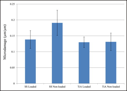
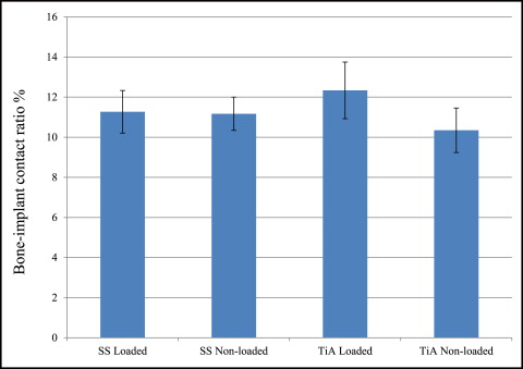
No significant difference in microdamage or bone-to-implant contact was found between the tension and compression sides of the implants, so data from the 2 sides were pooled in subsequent analyses. No significant differences were found in any histomorphometric measurements ( Table III ). The most, although not significant, microdamage burden occurred with the nonloaded stainless steel MSIs ( Fig 4 ). When subjected to 100 g of loading, the titanium alloy (0.13 ± 0.02 μm) and stainless steel (0.14 ± 0.03 μm) MSIs showed similar total microdamage burden values. A lack of significant differences in total microdamage burden was also observed between nonloaded stainless steel (0.19 ± 0.04 μm/μm) and titanium alloy (0.13 ± 0.03 μm/μm). According to Figure 5 , the loaded titanium alloy MSI displayed a trend toward an increase in the percentage of bone-to-implant contact (12.34% ± 1.41%) when compared with the loaded stainless steel (11.27% ± 1.06%), nonloaded titanium alloy (10.35% ± 1.11%), and nonloaded stainless steel (11.17% ± 0.83%). These differences did not prove to be statistically significant in any comparison.
| Cortical thickness (μm) | Implant surface length (μm) | Number of cracks | Crack length (μm) | Crack density (number of cracks/μm) ×10 −3 | Total microdamage burden (μm/μm) | |||||||
|---|---|---|---|---|---|---|---|---|---|---|---|---|
| Mean | SE | Mean | SE | Mean | SE | Mean | SE | Mean | SE | Mean | SE | |
| SS loaded | 894.0 | 62.0 | 2836.0 | 204.0 | 3.00 | 0.49 | 139.0 | 25.0 | 1.06 | 0.2 | 0.14 | 0.03 |
| SS nonloaded | 887.0 | 34.0 | 2625.0 | 126.0 | 4.17 | 0.61 | 113.0 | 14.0 | 1.59 | 0.3 | 0.19 | 0.04 |
| TiA loaded | 917.0 | 56.0 | 2914.0 | 178.0 | 3.75 | 0.58 | 106.0 | 10.0 | 1.29 | 0.2 | 0.13 | 0.02 |
| TiA nonloaded | 990.0 | 73.0 | 3217.0 | 284.0 | 3.08 | 0.60 | 127.0 | 22.0 | 0.96 | 0.2 | 0.13 | 0.03 |

Discussion
This study showed a 100% success rate in rabbit tibias, suggesting that stainless steel MSIs can be used as temporary orthodontic anchorage with at least the same efficacy as titanium alloy MSIs. To increase the secondary stability, recommendations have been made to provide a healing period before loading. But Miyawaki et al concluded that immediate loading with less than 2 N (203.9 g) was not detrimental to MSI success. Cornelis et al reported that MSIs have been successfully loaded immediately with 25 to 500 g (0.245-4.903 N) of tensile force perpendicular to the implant in various animal experiments. Chen et al suggested that immediate loading of less than 200 g will be successful. The immediate load on our implants was 100 g (0.98 N), a force sufficient to translate or tip teeth, and we found no differences in success rates between stainless steel and titanium alloy.
Our mean peak insertion torque values were 11.0 N-cm for titanium and 12.0 N-cm for stainless steel, similar to those in previous studies. Motoyoshi et al placed tapered titanium implants (1.6 × 8 mm) into the posterior alveolus in patients and suggested that placing MSIs with an insertion torque of 8 to 10 N-cm in cortical bone thicker than 1 mm improves the success rate. The minimum and average cortical bone thicknesses of rabbit tibia in our study were 0.89 and 0.92 mm, respectively. Baumgaertel and Hans reported similar human cortical bone thickness in the anterior maxilla and mandible depending on the distance from the alveolar crest. Our study mimicked the recommendations of Motoyoshi et al and achieved a 100% success rate. Interestingly, insertion torque of stainless steel MSIs was statistically higher than that of titanium alloy MSIs; this is desirable for improved primary stability. However, the difference was only 9% (stainless steel, 12 N-cm, vs titanium alloy, 11 N-cm), which may or may not have clinical consequences. According to Wilmes et al, the torque at fracture of Dentos titanium alloy MSIs of 1.6-mm diameter and 8-mm length varied from 17.0 to 23.4 N-cm. Our data suggest that an alarming number of titanium alloy MSIs could approach failure during insertion. This is a concern particularly in areas such as the second premolar or second molar regions, where the proximity to the inferior alveolar nerve canal complicates trephine procedures to remove a fractured MSI.
Our MSIs’ removal torque values were comparable with previously reported values for titanium alloy. Removal torque reflects the characteristics of the bone-to-implant interface and can be used to indirectly assess the anchorage capabilities of MSIs. It has been shown that stainless steel bone screws lack absolute osseointegration, and that they have lower removal torque values than commercially pure titanium screws, but no studies have compared the removal torque values of stainless steel and titanium alloy orthodontic MSIs. In this study, MSIs were placed in rabbit tibias for 6 weeks. Because rabbit bone turnover rate is approximately 3 times faster than that of humans, this translates to about 18 weeks in humans. At this time point, removal torque of the titanium alloy miniscrew represents the resistance to the degree of remodeled bone-to-implant contact rather than mechanical interlocking (ie, primary stability) between MSIs and host bone. Removal torque increases gradually with lamellar compaction during bone healing and reaches a significantly higher level 3 to 6 weeks after insertion in dogs and 12 weeks in rabbit tibias. Because of the potential for higher bone-to-implant contact, we expected to see a higher removal torque for titanium alloy MSIs than for stainless steel. However, our results showed similar MSI removal torque values for both after 6 weeks of healing, suggesting the same degree of direct bone-implant contact. This is further supported by our bone-to-implant contact data below.
Microdamage burden is the balance between microdamage creation and microdamage repair. If the balance shifts toward excess damage, with overloaded implants as an example, microdamage will accumulate and can eventually lead to loss of osseointegration. Huja et al and Huja and Roberts suggested that microdamage produced during implant placement initiates continuous and accelerated bone remodeling within 1 mm of dental implants. This zone remains less mineralized and more compliant, thus reducing additional microdamage and crack accumulation, a key for implant success. Similarly, microdamage can be created by pilot drilling and insertion of the MSIs. Our stainless steel and titanium alloy MSIs produced similar amounts of total microdamage burden in loaded and unloaded situations ( Fig 4 ). This could occur possibly because predrilling might relieve some of the stresses produced during implant placement. Compared with other studies of microdamage with MSI placement, we found less total microdamage burden after the 6-week healing period. The rapid bone turnover during the healing period probably explains the reduction in crack numbers and lengths. This is supported by the study of Serra et al, who found decreasing numbers of microcracks in bone adjacent to both loaded and unloaded MSIs after 1, 4, and 12 weeks of healing with new bone formation.
For osseointegrated dental implants, the biocompatibility of direct bone-to-implant contact achieved by titanium alloy is important. However, for easy removal of orthodontic MSIs, absolute osseointegration is undesirable. It has been demonstrated that MSIs with as little as 5% bone-to-implant contact can successfully resist orthodontic loads. This study shows a small bone-to-implant contact (about 11%), consistent with published values (10%-58%), but all MSIs were stable at the end of the study. At 6 weeks of healing in rabbit tibias (equivalent to about 18 weeks in humans), there was no significant difference in bone-to-implant contact among any groups. It is consistent with the study of Serra et al that no differences were found in the percentage of bone-to-implant contact and the percentage of bone area between the 2 sides (tension and compression) of the MSI, or between loaded and unloaded MSIs.
By using both tibias of each rabbit, we obtained a sufficient number of samples to test the mechanical properties and histomorphometric parameters. With this design, comparisons were primarily made within subjects, largely reducing potential variations between subjects. With a longer healing time, differences in bone-to-implant contact or removal torque might develop because of the possibility of formation of fibrous tissues associated with stainless steel. Clinical studies are required to evaluate the treatment efficacy of stainless steel MSIs.
Conclusions
Stainless steel and titanium alloy MSIs provided satisfactory mechanical stability when subjected to 100 g of immediate orthodontic loading for 6 weeks in rabbit tibias. A statistically significant increase in insertion torque was detected with stainless steel MSIs. There were no differences in histologic responses between stainless steel and titanium alloy MSIs with or without loading. It is suggested that titanium alloy and stainless steel MSIs are potentially suitable for clinical uses of immediate orthodontic loading.
Acknowledgments
We thank Carl Lerner and Cheryl Kantmann for professional animal care; Sharath Chedella, Rikin Patel, and Cassandra Vincke for histology assistance; Matthew Allen and Carol Bain for histomorphometric analysis; George Eckert for statistical analyses; James Baldwin for his valuable opinions; and Gayle Massa for her kind assistance.
Ryan N. Brown and Brent E. Sexton are joint first authors and contributed equally to this work.
All authors have completed and submitted the ICMJE Form for Disclosure of Potential Conflicts of Interest, and none were reported.
Funded by the Support for the Recruitment of Under-Represented Faculty fund , Indiana University-Purdue University.
Results
No rabbit experienced infection or significant weight loss. All MSIs demonstrated mechanical stability as indicated by a clinical assessment approach (mobility <1 mm when gently luxated with forceps). After 6 weeks, all MSIs were stable with no mobility. Insertion and removal torque values are reported in Table II . ANOVA showed that stainless steel MSIs required significantly higher insertion torque (12.00 ± 0.25 N-cm) than did titanium alloy MSIs (11.01 ± 0.24 N-cm) ( P = 0.0048 <0.05). There was no difference in removal torque between stainless steel and titanium alloy: 4.4 ± 2.3 N-cm and 4.4 ± 1.7 N-cm, respectively. Removal torque was not significantly associated with loading.
| Insertion torque (N-cm) | Removal torque (N-cm) | |||
|---|---|---|---|---|
| Mean | SE | Mean | SE | |
| SS loaded | 12.00 | 0.25 | 3.67 | 0.32 |
| SS nonloaded | 3.71 | 0.38 | ||
| TiA loaded | 11.01 | 0.24 | 4.33 | 0.45 |
| TiA nonloaded | 4.79 | 0.47 | ||
No significant difference in microdamage or bone-to-implant contact was found between the tension and compression sides of the implants, so data from the 2 sides were pooled in subsequent analyses. No significant differences were found in any histomorphometric measurements ( Table III ). The most, although not significant, microdamage burden occurred with the nonloaded stainless steel MSIs ( Fig 4 ). When subjected to 100 g of loading, the titanium alloy (0.13 ± 0.02 μm) and stainless steel (0.14 ± 0.03 μm) MSIs showed similar total microdamage burden values. A lack of significant differences in total microdamage burden was also observed between nonloaded stainless steel (0.19 ± 0.04 μm/μm) and titanium alloy (0.13 ± 0.03 μm/μm). According to Figure 5 , the loaded titanium alloy MSI displayed a trend toward an increase in the percentage of bone-to-implant contact (12.34% ± 1.41%) when compared with the loaded stainless steel (11.27% ± 1.06%), nonloaded titanium alloy (10.35% ± 1.11%), and nonloaded stainless steel (11.17% ± 0.83%). These differences did not prove to be statistically significant in any comparison.
| Cortical thickness (μm) | Implant surface length (μm) | Number of cracks | Crack length (μm) | Crack density (number of cracks/μm) ×10 −3 | Total microdamage burden (μm/μm) | |||||||
|---|---|---|---|---|---|---|---|---|---|---|---|---|
| Mean | SE | Mean | SE | Mean | SE | Mean | SE | Mean | SE | Mean | SE | |
| SS loaded | 894.0 | 62.0 | 2836.0 | 204.0 | 3.00 | 0.49 | 139.0 | 25.0 | 1.06 | 0.2 | 0.14 | 0.03 |
| SS nonloaded | 887.0 | 34.0 | 2625.0 | 126.0 | 4.17 | 0.61 | 113.0 | 14.0 | 1.59 | 0.3 | 0.19 | 0.04 |
| TiA loaded | 917.0 | 56.0 | 2914.0 | 178.0 | 3.75 | 0.58 | 106.0 | 10.0 | 1.29 | 0.2 | 0.13 | 0.02 |
| TiA nonloaded | 990.0 | 73.0 | 3217.0 | 284.0 | 3.08 | 0.60 | 127.0 | 22.0 | 0.96 | 0.2 | 0.13 | 0.03 |

Anchorage management is the key to orthodontic success, but reliance on patient compliance has made it a true challenge. Therefore, the use of miniscrew implants (MSIs) for skeletal anchorage has rapidly spread. MSIs have been successfully used for space closure, intrusion, extrusion, molar uprighting, open-bite closure, and a continuously increasing variety of other anchorage needs. Thus, a better understanding of these devices is essential to facilitate patient care.
Many studies have demonstrated the effectiveness of MSIs. A recent meta-analysis reported success rates of 87.7% and above. This is relatively low considering that dental implant success rates are 95% and higher. Although many factors affect MSI success rates, implant tip breakage during insertion is a serious complication mainly because of the need for surgical removal. As the MSI diameter decreases, it weakens, leading to potential breakage when the insertion or removal torque exceeds the torsional strength. Thus, stainless steel, because it is stronger than the traditional titanium alloy, would reduce breakage.
Stainless steel bone screws have been widely used for fracture fixation. Unlike titanium alloy, stainless steel bone screws tend to develop a fibrous tissue interface between the screw and bone ; this lowers removal torque, leading to easier retrieval. MSIs are generally made of titanium alloys. Titanium is a highly biocompatible material that allows for direct bone contact (osseointegration) between endosseous dental implants and the host bone. However, the high degree of osseointegration required for dental implants is not a requirement for orthodontic MSIs to function as anchorage devices.
Promising results have been reported for stainless steel MSIs used for en-masse space closure. However, properties such as primary stability and bone-healing responses still need to be examined. The former, defined as the mechanical retention at insertion, is quantified by insertion torque. A systematic review suggested that a wide range of insertion torque values can achieve high MSI success rates, but excessive insertion torque might cause detrimental effects such as bone necrosis and increased bone microdamage. Microdamage initiates rapid bone remodeling and healing, but if it accumulates, bone mechanical properties are reduced, thus potentially contributing to MSI failure.
With bone healing after insertion, new bone forms and remodels surrounding the implant. The bone-to-implant contact ratio (implant surface in contact with bone divided by total implant surface) is commonly used to indicate the degree of bone-implant adaptation. As little as 5% of bone-to-implant contact has been shown to successfully resist orthodontic loads. Removal torque is another indicator that reflects bone-to-implant contact and the MSI’s anchorage capability. Clinically, removal torque of titanium alloy MSIs varies from 4 to 16 N-cm, depending on surface treatments. It is speculated that fibrous tissues develop around stainless steel screw threads, leading to reduced bone-to-implant contact and removal torque with increased potential for failure.
Immediate loading of MSIs, which is now common practice, might alter the microdamage healing process and the resulting bone-to-implant contact. The purpose of this study was to evaluate the stability, insertion torque, microdamage burden, bone-to-implant contact, and removal torque of stainless steel and titanium alloy MSIs with or without immediate orthodontic loading. We hypothesized that stainless steel and titanium alloy miniscrews would produce similar values as indicators of mechanical stability, since both were expected to have low degrees of osseointegration.
Material and methods
Forty-eight stainless steel (medical class 316 LVM; Dentos, Daegu, South Korea) and 48 titanium alloy (Ti6Al4V; Dentos) self-threading MSIs (length, 6 mm; diameter, 1.6 mm), of identical design and fabrication, were inserted into 12 male New Zealand white rabbits, 4 to 5 months old and weighing 3.5 to 4.5 kg (Harlan Laboratory, Indianapolis, Ind). The Institutional Animal Care and Use Committee approval was obtained from Indiana University-Purdue University, Indianapolis. The 24 tibias of the 12 rabbits were assigned to 1 of the 4 experimental groups using the random block design outlined in Table I .
| Location | Rabbits 3, 6, 10 | Rabbits 4, 8, 11 | Rabbits 1, 9, 12 | Rabbits 2, 5, 7 | ||||
|---|---|---|---|---|---|---|---|---|
| Left tibia | Right tibia | Left tibia | Right tibia | Left tibia | Right tibia | Left tibia | Right tibia | |
| Removal torque | Histology | Histology | Removal torque | Removal torque | Histology | Histology | Removal torque | |
| 1 (proximal) | SS-NL | SS-L | SS-NL | SS-L | TiA-NL | TiA-L | TiA-NL | TiA-L |
| 2 | TiA-NL | TiA-L | TiA-NL | TiA-L | SS-NL | SS-L | SS-NL | SS-L |
| 3 | SS-L | SS-NL | SS-L | SS-NL | TiA-L | TiA-NL | TiA-L | TiA-NL |
| 4 (distal) | TiA-L | TiA-NL | TiA-L | TiA-NL | SS-L | SS-NL | SS-L | SS-NL |
Two stainless steel and 2 titanium alloy MSIs were placed in each tibia ( Fig 1 ), 1 of each type in the proximal portion of the tibia (locations 1 and 2), and 1 of each type in the distal portion (locations 3 and 4), as detailed in Table I . Forty-eight (24 adjacent pairs) implants were immediately loaded with a GAC Sentalloy 3-mm closed-coil spring (Dentsply GAC International, Bohemia, NY) applying a relatively continuous force of 100 g (0.98 N). The force magnitude was verified with a digital force gauge (Lutron Electronics Enterprise, Taipei, Taiwan) during placement and removal. The other 48 MSIs remained unloaded.
Meloxicam (0.2 mg/kg subcutaneously; Boehringer Ingelheim, St Joseph, Mo) was given 40 to 60 minutes before the procedure as an analgesic. A single dose of meloxicam has been shown to have no effects on bone healing adjacent to implant sites. At the time of anesthesia, the animals were induced by acepromazine (0.6 mg/kg) and butorphanol tartrate (0.75 mg/kg). After initial induction, anesthesia was maintained with isoflurane (3.5% at 1.5 L/m) via gas mask. One dose of the broad spectrum antibiotic enrofloxacin at 4 mg per kilogram subcutaneously was given at the time of surgery.
After incision and blunt dissection through skin, fascia, and periosteum, the middiaphyseal portion of the proximal and distal tibia was exposed. The MSI pilot holes were drilled 9 mm apart, each with a new 1.3 mm × 7/10/14-mm increment twist drill at low speed with copious saline-solution irrigation. The MSIs were gently screwed into place by an operator (R.N.B) with an insertion torque screwdriver (DI-5N-RL2; Imada, Northbrook, Ill), until the implant shoulder was level with the bone surface. The peak insertion torque and primary stability were recorded. To assess clinical insertion and removal stabilities, forceps were used to gently move the MSIs, and any MSI that showed mobility greater than 1 mm was deemed a failure. In the loaded groups, the Sentalloy coil springs were applied. To limit tissue ingrowth, they were covered with medical-grade latex-free tubing ( Fig 1 ; Tygon; U.S. Plastic, Lima, Ohio).
To completely cover the implant and the spring, the fascia and the skin were closed in separate layers with resorbable 4.0 Monocryl sutures (Ethicon, San Angelo, Tex), and aluminum foil was wrapped around the tibia to protect the sutures. After surgery, Baytril (4 mg/kg subcutaneously) was administered once daily for 4 days. Meloxicam (0.2 mg/kg subcutaneously) was administered once daily for 2 days. Buprenex (Reckitt Benckiser Pharmaceuticals, Richmond, Va) was used for breakout pain (0.01-0.05 mg/kg subcutaneously, at 8-24 hours) as needed. The animals were checked daily for body temperature, hydration status, activity, food and water consumption, and conditions at the operative site. Alizarin (20 mg/mL) and calcein (10 mg/mL) bone labels were injected at weeks 4 and 5, respectively, after MSI placement to allow dynamic histomorphometry measures. Six weeks after surgery, the animals were euthanized with B-euthanasia 1 mL per 4.5 kilograms intravenously (Merck Animal Health, Summit, NJ).
Immediately after the rabbits were euthanized, 24 stainless steel and 24 titanium alloy (half loaded, half unloaded) MSIs and the surrounding bones were dissected for measuring peak removal torque ( Table I ) with a digital torque gauge (BGI torque gauge; Mark-10, Copiague, NY). The gauge was positioned on the hexagonal implant head, and increasing torque was applied to the point of first “give.” The peak torque registered by the instrument was recorded.
The remaining 48 MSI blocks were dissected free and fixed for 2 weeks in 70% ethanol for histomorphometric analysis. Staining with basic fuchsin was performed according to published procedures. This technique allows for the differentiation of cracks caused by the implant or drilling (stained) from cracks formed during grinding and polishing of the histologic slides (unstained). After staining, the blocks were embedded in methylmethacrylate and sectioned (IsoMet low speed saw; Buehler, Lake Bluff, Ill) along the plane through the length of the implant and parallel to the tibia. Sections were ground and polished to 150 to 170 μm in thickness with an Exakt system (EXAKT Technologies, Oklahoma City, Okla).
Microdamage was identified under an epifluorescence microscope (Leica Microsystems, Buffalo Grove, Ill) with an excitation wave length of 546 using Osteo II software (Bioquant Image Analysis, Nashville, Tenn) following the same criteria published previously. Cortical bone thickness near the implant was measured under 4× objective magnification in triplicate and averaged. Microdamage was assessed using 10× objective magnification ( Fig 2 ) on both sides (tension and compression for the loaded MSIs; proximal and distal for unloaded MSIs) of all 48 implants. Crack length and MSI implant surface length in bone were measured. The crack density (number of total cracks/implant surface length) and the total microdamage burden per surface length (number of cracks × average crack length/implant surface length) were calculated for each specimen. All measurements were made by the same blinded examiner (B.E.S.). Intrarater reliability was 0.93 for analysis of microcrack parameters and was based on intraclass correlation between 2 blinded measurements with a 2-week interval on 10 randomly selected sections.
After microdamage and bone remodeling rate analyses, the samples were counterstained in light green stain (L1886-25G; Sigma-Aldrich, St Louis, Mo) for 10 minutes to impart a green color selective to bone tissue. Under the bright field of the microscope, the images of the implant and surrounding bone were captured with 4× magnification. Multiple images of each MSI were merged using Image Composite Editor software (Microsoft, Redmond, Wash). The borders of the MSIs were traced, and total bone-to-implant contact length at the midpoint of the vertical axis was measured on the sides of tension and compression ( Fig 3 ). The bone-to-implant contact ratio was calculated using the following formula: bone-to-implant contact ratio = (length of bone in direct contact with implant/total implant length) × 100%.

Statistical analysis
Insertion torque, removal torque, microdamage, and bone-to-implant contact measurements were summarized. Mixed-model analysis of variance (ANOVA) models were used to investigate the differences including the effects of metal (titanium alloy vs stainless steel), loading (loaded vs unloaded), location of implant, and the 2-way interactions between these factors. Comparisons between groups were evaluated with the level of significance set at 0.05 using SAS software (SAS Institute, Cary, NC). Distributions of the data were examined, and no transformations of the measurements (eg, natural logarithm) were necessary to satisfy the ANOVA assumptions. Based on data from a previous study in dogs, with a sample size of 12 rabbits, our study would have 80% power to detect a microdamage difference of 0.7 between the titanium alloy and the stainless steel implants, between loaded and unloaded implants, or between implant locations.
Results
No rabbit experienced infection or significant weight loss. All MSIs demonstrated mechanical stability as indicated by a clinical assessment approach (mobility <1 mm when gently luxated with forceps). After 6 weeks, all MSIs were stable with no mobility. Insertion and removal torque values are reported in Table II . ANOVA showed that stainless steel MSIs required significantly higher insertion torque (12.00 ± 0.25 N-cm) than did titanium alloy MSIs (11.01 ± 0.24 N-cm) ( P = 0.0048 <0.05). There was no difference in removal torque between stainless steel and titanium alloy: 4.4 ± 2.3 N-cm and 4.4 ± 1.7 N-cm, respectively. Removal torque was not significantly associated with loading.
| Insertion torque (N-cm) | Removal torque (N-cm) | |||
|---|---|---|---|---|
| Mean | SE | Mean | SE | |
| SS loaded | 12.00 | 0.25 | 3.67 | 0.32 |
| SS nonloaded | 3.71 | 0.38 | ||
| TiA loaded | 11.01 | 0.24 | 4.33 | 0.45 |
| TiA nonloaded | 4.79 | 0.47 | ||
No significant difference in microdamage or bone-to-implant contact was found between the tension and compression sides of the implants, so data from the 2 sides were pooled in subsequent analyses. No significant differences were found in any histomorphometric measurements ( Table III ). The most, although not significant, microdamage burden occurred with the nonloaded stainless steel MSIs ( Fig 4 ). When subjected to 100 g of loading, the titanium alloy (0.13 ± 0.02 μm) and stainless steel (0.14 ± 0.03 μm) MSIs showed similar total microdamage burden values. A lack of significant differences in total microdamage burden was also observed between nonloaded stainless steel (0.19 ± 0.04 μm/μm) and titanium alloy (0.13 ± 0.03 μm/μm). According to Figure 5 , the loaded titanium alloy MSI displayed a trend toward an increase in the percentage of bone-to-implant contact (12.34% ± 1.41%) when compared with the loaded stainless steel (11.27% ± 1.06%), nonloaded titanium alloy (10.35% ± 1.11%), and nonloaded stainless steel (11.17% ± 0.83%). These differences did not prove to be statistically significant in any comparison.


