Introduction
The aims of this study were to evaluate how head orientation interferes with the amounts of directional change in 3-dimensional (3D) space and to propose a method to obtain a common coordinate system using 3D surface models.
Methods
Three-dimensional volumetric label maps were built for pretreatment (T1) and posttreatment (T2) from cone-beam computed tomography images of 30 growing subjects. Seven landmarks were labeled in all T1 and T2 volumetric label maps. Registrations of T1 and T2 images relative to the cranial base were performed, and 3D surface models were generated. All T1 surface models were moved by orienting the Frankfort horizontal, midsagittal, and transporionic planes to match the axial, sagittal, and coronal planes, respectively, at a common coordinate system in the Slicer software (open-source, version 4.3.1; http://www.slicer.org ). The matrix generated for each T1 model was applied to each corresponding registered T2 surface model, obtaining a common head orientation. The 3D differences between the T1 and registered T2 models, and the amounts of directional change in each plane of the 3D space, were quantified for before and after head orientation. Two assessments were performed: (1) at 1 time point (mandibular width and length), and (2) for longitudinal changes (maxillary and mandibular differences). The differences between measurements before and after head orientation were quantified. Statistical analysis was performed by evaluating the means and standard deviations with paired t tests (mandibular width and length) and Wilcoxon tests (longitudinal changes). For 16 subjects, 2 observers working independently performed the head orientations twice with a 1-week interval between them. Intraclass correlation coefficients and the Bland-Altman method tested intraobserver and interobserver agreements of the x, y, and z coordinates for 7 landmarks.
Results
The 3D differences were not affected by the head orientation. The amounts of directional change in each plane of 3D space at 1 time point were strongly influenced by head orientation. The longitudinal changes in each plane of 3D space showed differences smaller than 0.5 mm. Excellent intraobserver and interobserver repeatability and reproducibility (>99%) were observed.
Conclusions
The amount of directional change in each plane of 3D space is strongly influenced by head orientation. The proposed method of head orientation to obtain a common 3D coordinate system is reproducible.
Highlights
- •
Changes from 3-dimensional models with and without head orientation were evaluated.
- •
A new method for head orientation to establish a common coordinate system is proposed.
- •
Changes in each plane of 3-dimensional space are strongly influenced by head orientation.
- •
A common coordinate system will standardize the directionality of changes in patients.
- •
The proposed method of head orientation is reproducible.
A correct jaw relationship depends on adequate interactions between a series of basal and dentoalveolar adaptations in the sagittal, coronal, and axial planes induced by growth and treatment. Serial cephalometric radiographs and cone-beam computed tomography (CBCT) have been used for evaluation and understanding of the changes resulting from these interactions.
With the advent of 3-dimensional (3D) evaluations in orthodontics, 3D models generated from CBCT have been used to assess the modifications caused by growth or different kinds of treatment. Facial changes can be quantified by obtaining measurements in cross-sectional slices of scans, in 3D surface models at 2 or more time points, or between scans or surface models registered relative to a stable structure of reference such as the cranial base (a validated voxel-based method to assess posttreatment changes in growing and adult patients).
Dental and skeletal displacements and bone remodeling of the maxilla and the mandible can be quantified by 3D linear and angular measurements based on homologous landmarks defined by observers, or by 3D linear surface distances in thousands of triangular meshes in surface models (that can be graphically displayed as color-coded surface maps). Since the original work of Moyers and Bookstein, advanced morphometric methods (ie, that measure morphology or form) using semilandmarks, matrices of interlandmark distances (Euclidean Distances Matrix Analysis), curved distances, or tensor-based morphometry have been proposed. However, those methods involve complex mathematical information that is not easily interpreted by clinicians.
Although 3D linear distances are a simplification of complex morphologic changes, they provide relevant clinical evaluations of changes in the space related to differences between time points. Such 3D distances express different amounts of changes in the 3 axes of the space, and clinical questions require more precise information regarding the location and amount of changes in each direction (x-, y-, and z-axes). In particular, clinicians plan their expected results of treatment based on anterior, posterior, inferior, superior, medial, or lateral movements and displacements.
However, quantification of directional differences in each plane of 3D space (3D components) can be obtained by decomposing the distances between projections of the 3D landmarks in the x, y, and z coordinate system. For any study sample comprising scans with different head orientations, the understanding of the direction of maxillomandibular changes for all patients depends on the establishment of a common coordinate system, so that directional projections can be consistent across patients. Inconsistency of head orientation across patients in a study sample would lead to inconsistent measurements; eg, anterior displacements would become more inferior with the head in clockwise rotation, or would become more lateral with the head in lateral rotation. Additionally, the identification of some landmark locations that depend on head orientation can be affected if the head is rotated or laterally tilted as well (eg, pogonion is the most anterior point of the anterior contour of the symphysis, and it can be misplaced with head rotation).
Reliable and accurate measurements should be used for a precise diagnosis and for assessment of treatment outcomes. Inconsistency in these measurements can adversely affect research conclusions and treatment plans. Some previous studies have investigated the influence of head position before the acquisition on the accuracy of the 3D measurements. Those findings indicated that measurements based on 3D CBCT surface images were accurate, and small variations in the patient’s head position did not influence measurement accuracy. However, the rotational angles used in these previous studies do not reflect the actual differences in patient positioning during the CBCT acquisition. The rotations tested were arbitrary because no information was found in the literature with regard to the incidence and extension of patient positioning differences during scan acquisitions. Therefore, clinical studies based on the differences between measurements from 2 time points using the projections of the changes in the x-, y-, and z-axes are still necessary.
This study had 3 objectives: to evaluate the influence of head orientation in the assessment of 3D longitudinal changes and in each plane of 3D space, to propose a method for reaching a common coordinate system using 3D models, and to test the intraobserver and interobserver reproducibility of the proposed method.
Material and methods
The sample consisted of 30 growing patients (ages, 9-13 years) who had 2 CBCT scans available at 2 time points (T1 and T2) taken at least 18 months apart with a 16 × 22-cm field of view, randomly selected from records (photographs and CBCT volumes) of patients from the Department of Orthodontics of Federal University of Rio de Janeiro in Brazil. Images were selected using the following inclusion criteria: (1) acceptable-quality images and (2) sufficient field of view to include basion, porion, glabella, and chin. The exclusion criteria were (1) motion artifacts, (2) many metallic artifacts, and (3) orthodontic appliances.
This study was approved by the University of Rio de Janeiro institutional review board (971.935).
First, the DICOM files were converted to deidentified gipl files using ITK-SNAP open-source software ( http://www.itksnap.org ). Then the 3D image analysis procedures followed these steps.
- 1.
Approximation of the T1 and T2 scans. The T1 and T2 scans were approximated by the same observer (A.C.O.R.) having as a reference the best fit of the cranial base outlines in 3D multiplanar cross-sections using the tool transforms in Slicer open-source software (version 4.3.1; http://www.slicer.org ).
- 2.
Construction of 3D volumetric label maps of the maxilla (segmentation). The construction of the 3D volumetric label maps for the T1 and T2 scans was performed with the ITK-SNAP software. The automatic segmentation procedures in ITK-SNAP use active contour methods to compute feature images based on the CBCT images’ gray level intensity and boundaries. ITK-SNAP allows adjustment of the parameters for automatic detection of intensities and boundaries as well as user interactive editing of contours. The anatomic structures that were segmented indicated to the software in which areas it should look for corresponding voxels. After registration, the segmentations (volumetric label maps) were used to build 3D surface models that were loaded in VAM software (Vectra; Canfield Scientific, Fairfield, NJ).
- 3.
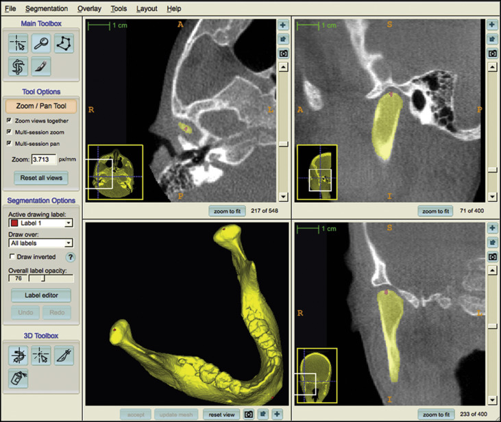
Placement of landmarks on the 3D volumetric label maps at T1 and T2. One label with a different color of the 3D volumetric maps was used by 1 observer (A.C.O.R.) to label 4 landmarks in the maxilla and 3 landmarks in the mandible in all T1 and T2 models to prevent any landmark identification errors. The landmarks were (1) anterior nasal spine, (2) posterior nasal spine, (3) maxillary right first molar, (4) maxillary left first molar, (5) right condylion, (6) left condylion, and (7) pogonion. The landmarks were labeled in 2 consecutive slices. Sagittal, axial, and coronal slices as well as the 3D reconstructions of the image were used for landmark positioning in the ITK-SNAP software ( Fig 1 ). The 3D models, labeled with the landmarks, were used for the registration procedures to prevent errors caused by segmentation or landmark placement.

Fig 1 Images showing mandibular 3D volumetric model with 3 prelabeled landmarks (right and left condylions and pogonion) used to obtain reliable landmark identification for comparisons between before and after orientations and for testing the reproducibility of the method. - 4.
Voxel-based registration procedures. These procedures used the cranial base anatomic structures as masks for reference, indicating to the software in which stable areas it should look for corresponding voxels. A fully automated voxel-wise rigid growing registration method (that takes into account that the images have different sizes because they are from different times, but applies only 6 degrees of freedom of rotation and translation to the T2 scan) was performed with the Slicer software. After registration, the T2 label models resulting from the registration and the T1 label models were saved as surface mesh files (.stl files) with the Slicer software.
- 5.
Landmark-based quantitative assessments in the VAM software. The 3D surface mesh models with landmarks prelabeled were loaded into VAM software, and the coordinates (x, y, and z) were generated for each landmark on the T1 and the registered T2 surface models. Two kinds of quantitative assessments of the differences between landmarks were performed:
- a.
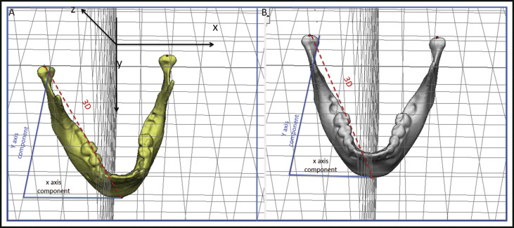
At 1 time point (any time point, initial or follow-up): the 3D distance and its components in each plane of the space were measured for mandibular width and length. The 3D measurements corresponded to the Euclidean distances between the right and left condylions, and the right condylion and pogonion. Changes in each plane of the space were assessed by the distances between the corresponding coordinates of the corresponding landmarks (right and left condylions, and right condylion and pogonion), which represented the transversal (x-axis), anteroposterior (y-axis), and vertical (z-axis) differences ( Fig 2 ).

Fig 2 Representation of 3D measurements and changes in each component of the 3D space (x and y components). Distances between landmark coordinates (right and left condylions), representing the transversal (x-axis), anteroposterior (y-axis), and vertical (z-axis) differences. A, Before head orientation; B, after head orientation. - b.
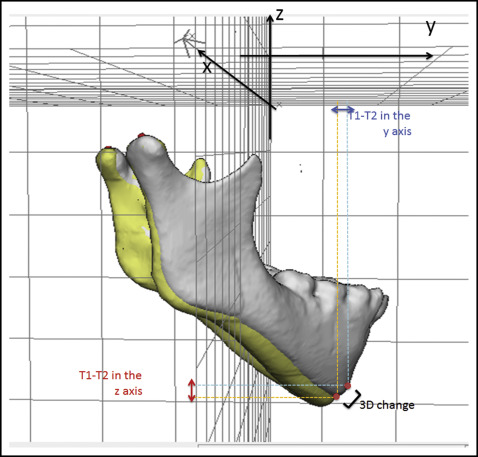
Differences between 2 time points (T1 and T2): the 3D distance and its components in each plane of the space for displacements of the maxilla (distance between anterior nasal spine at T1 and T2) and the mandible (difference between pogonion at T1 and T2) were measured in relation to the cranial base (cranial base registration). The 3D measurements corresponded to the Euclidean distances between the T1 and T2 anterior nasal spine landmarks and the T1 and T2 pogonion landmarks. The distances between corresponding coordinates of corresponding landmarks (anterior nasal spine at T1 and T2, and pogonion at T1 and T2), which corresponded to the transversal (x-axis), anteroposterior (y-axis), and vertical (z-axis) displacements were also performed as changes in each plane of space (3D components) ( Fig 3 ).

Fig 3 Representation of the 3D differences and changes in each component of the 3D space (y and z components) between 2 time points that were registered on the cranial base.
- a.
- 6.
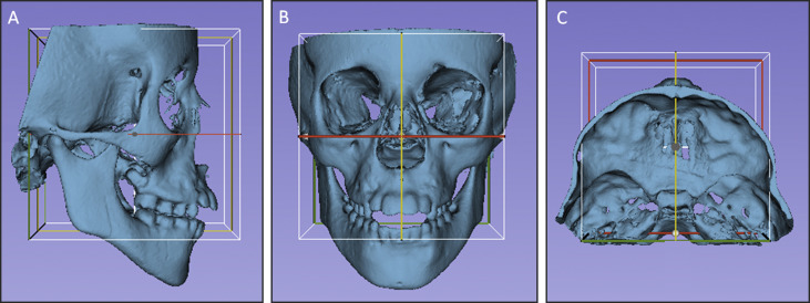
Head orientation. The T1 surface models were oriented using the transforms tool in Slicer software ( Fig 4 ). All T1 surface models were moved by orienting its Frankfort horizontal, midsagittal, and transporionic planes to match the axial, sagittal, and coronal planes, respectively, at a common coordinate system in the Slicer software. The 3D orientation was achieved using 3 planes defined by at least 3 landmarks or 2 landmarks and a plane: Frankfort horizontal, midsagittal, and transporionic planes. The midsagittal plane was defined by glabella, crista galli, and basion. The Frankfort horizontal plane was defined bilaterally by the right and left porions and the right and left orbitales. The transporionic plane was defined bilaterally by the porion landmarks and is perpendicular to the Frankfort horizontal plane. The Slicer software displays a fixed 3D coordinate system (red, yellow, and green planes in Fig 4 ) that was used as the reference to orient the 3D models. Using the axial, coronal, and sagittal views of the 3D models, the T1 model was moved to orient the midsagittal plane vertically and coincident with the yellow (sagittal) plane of the 3D coordinate system. The Frankfort horizontal plane was oriented to match the red (axial) plane. The horizontal transporionic line was oriented to be coincident with the intersection between the red (axial) and green (coronal) planes in both sides of the head. The matrix (file that contains the information relative to translational and rotational movements to obtain the orientation) generated from this step was applied to the T2 registered surface model, reaching the same head orientation. Then the same measurements performed in step 5 (3D components and 3D differences) were repeated for the oriented surface models (T1 and registered T2).

Fig 4 Figures illustrating the head orientation procedure: A, lateral view; B, frontal view; and C, superior view. The midsagittal plane of the 3D model was oriented vertically and coincident with the yellow (sagittal) plane, the Frankfort horizontal plane was oriented horizontally to coincide with the red (axial) plane, and the transporionic line was oriented to match with the intersection of the red (axial) and green (coronal) planes. The white box corresponds to the limits of the 3 cited planes, and it was not used as a reference for orientation. - 7.
Comparisons between measurements at the 1 time point scan, before and after head orientation. Assessments of mandibular width (distance from right to left condylion) and length (distance from right condylion to pogonion) were performed in the 3D surface models to evaluate whether the values were influenced by the head positioning. Three-dimensional measurements and 3D components obtained before and after head orientation were compared.
- 8.
Comparisons between longitudinal changes, before and after head orientation based on registered 3D models (cranial base registration). Assessments of the positional changes (displacements caused by growth or treatment) between the 3D surface models (T2-T1) were performed comparing the T2 to T1 changes before head orientation vs the T2 to T1 changes after head orientation to evaluate the head positioning displacement. Two measurements were performed: maxillary (anterior nasal spine displacement) and mandibular displacement (pogonion displacement).
- 9.
Assessment of the intraobserver and interobserver reproducibility. For 16 subjects, the procedure of head orientation was performed at 2 times (orientations 1 and 2) with a 1-week interval between them by 2 observers (A.C.O.R., M.S.Y.), working independently. These observers were trained and calibrated to perform the head orientation using a set of 30 3D surface models not included in this study. To test the interobserver reproducibility, the x, y, and z coordinates (generated by the 2 observers) of corresponding landmarks were compared after each of the 2 orientation procedures. The intraobserver reproducibility was tested by comparing the x, y, and z coordinates from the 2 repeated head orientations for each observer.
Statistical analysis
Statistical analyses were carried out with MedCalc (version 14.10.2; MedCalc Software, http://www.medcalc.org/ ). Descriptive statistics of the differences between the before and after head orientations for the 3D changes and their components in each plane of the 3D space included means and standard deviations. The normality of the data was tested using the Shapiro-Wilk test. The comparison of measurements before and after head orientation at the 1 time-point scan was performed by paired t test. The Wilcoxon test was run to compare longitudinal changes before and after head orientation based on the cranial base registration. The statistical significance was set at P <0.05.
Intraobserver and interobserver agreement was tested with the intraclass correlation coefficient (with 2-way random effects model) and Bland-Altman plots of the 95% limits of agreement, average differences ±1.96 of the standard deviation of the differences, and evaluations of the concordance between corresponding x, y, and z coordinate pairs from corresponding landmarks generated from the 3D surface mesh models after head orientation by both observers.
Results
Table I shows the comparison of measurements before and after head orientation at 1 time point for the 3D distances and 3D components (x, y, and z distances). The 3D distances representing the width and length of the mandible did not show differences caused by head positioning. The measurements based on each of the 3D components, which represent distances in the x-, y-, and z-axes, displayed significant statistical differences in all measurements.
| Measurement | Mean ± SD (mm) | B.or-A.or (mm) | P value (paired t test) | |
|---|---|---|---|---|
| Mandibular width (Dist RCo−LCo) | ||||
| 3D | B.or | 89.94 (±6.69) | 0.01 | 0.88 |
| A.or | 89.95 (±6.74) | |||
| x component | B.or | 89.26 (±6.70) | 0.62 | 0.00 ∗ |
| A.or | 89.88 (±6.71) | |||
| y component | B.or | 9.61 (±5.37) | 8.15 | 0.00 ∗ |
| A.or | 1.46 (±1.19) | |||
| z component | B.or | 2.37 (±1.48) | 1.07 | 0.01 ∗ |
| A.or | 1.30 (±1.15) | |||
| Mandibular length (Dist RCo−Pog) | ||||
| 3D | B.or | 109.88 (±7.32) | 0.25 | 0.10 |
| A.or | 110.13 (±7.35) | |||
| x component | B.or | 50.16 (±6.17) | 4.73 | 0.00 ∗ |
| A.or | 45.43 (±4.28) | |||
| y component | B.or | 57.03 (±15.93) | 9.18 | 0.00 ∗ |
| A.or | 66.21 (±8.23) | |||
| z component | B.or | 77.44 (±9.32) | 2.82 | 0.01 ∗ |
| A.or | 74.62 (±7.94) | |||
Stay updated, free dental videos. Join our Telegram channel

VIDEdental - Online dental courses


