Introduction
Chairside oral scanners allow direct digital acquisition of the intraoral situation and can eliminate the need for conventional impressions. In this study, we aimed to assess accuracy, scan time, and patient acceptance of a chairside oral scanner when used for full-arch scans; these are critical factors for acceptance of this technology in the orthodontic setting.
Methods
Fifteen patients had digital models made from both intraoral scans (Lava COS; 3M ESPE, St Paul, Minn) and alginate impressions. Each procedure was timed, and patient preference was assessed with a survey. In addition, digital models were made from 5 plaster model pairs using the intraoral scanner and an orthodontic model scanner. Model pairs were digitally superimposed, and differences between models were quantified. Accuracy was assessed using the Bland-Altman method. Time differences were tested for statistical significance with the Student t test.
Results
Digital models made using the chairside oral scanner and either impressions or the orthodontic model scanner did not differ significantly. The chair time required to take impressions was significantly shorter than the time required for the intraoral scans. When processing time was included, the time requirement did not differ significantly between methods. Although 73.3% of the patients preferred impressions because they were “easier” or “faster,” 26.7% preferred the scan because it was “more comfortable.”
Conclusions
Despite the high accuracy of chairside oral scanners, alginate impressions are still the preferred model acquisition method with respect to chair time and patient acceptance. As digital technology continues to progress, intraoral scanning may become more accepted for use in orthodontics.
Highlights
- •
Digital models made from intraoral scans are as accurate as those made from alginate impressions.
- •
Alginate impressions require less chairside time and are preferred over intraoral scans by most patients.
- •
As technology continues to progress, intraoral scans may become more accepted in orthodontics.
Digital models have rapidly been accepted in the orthodontic community for diagnosis, treatment planning, and documentation of treatment outcomes, and a growing number of orthodontists are incorporating these models into their practices. Currently, most digital models are made from alginate impressions, which are either scanned directly or poured in plaster and then scanned. The development of chairside oral scanners now allows direct digital acquisition of the clinical situation in the mouth; this can eliminate the need for conventional impressions.
Obviously, any potential advantages of direct scanning technology would be negated if its accuracy and efficiency were not comparable with the conventional approach of model acquisition with alginate impressions. Although intraoral scanners have been used in dentistry for several years, most information regarding their accuracy is limited to single elements commonly used in restorative dentistry, such as crowns, inlays, onlays, and bridges. Data on the accuracy of digital models for orthodontic purposes acquired with this technology are scarce, and little information is currently available regarding the time requirement for and the patient acceptance of full-arch scanning. These factors will be critical in determining the acceptance of direct scanning technology in the orthodontic setting.
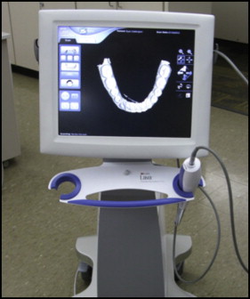
The aims of this study were therefore to assess the relative accuracy of digital orthodontic models obtained with a direct chairside intraoral scanner and to compare the time requirement for and the patient acceptance of this model acquisition method with the conventional approach with alginate impressions. The direct intraoral scanner used was the Lava COS (3M ESPE, St Paul, Minn; Fig 1 ).
Material and methods
Approval to conduct this study was obtained from the institutional review board at the University of Minnesota, and informed consent was obtained from all study participants. Fifteen consecutive patients presenting for routine orthodontic treatment who were willing to participate were included in the study. The study sample consisted of 6 male and 9 female patients with a mean age of 19.5 ± 9.9 years (range, 12.8-52.4 years). Inclusion criteria included full permanent dentition from first molar to first molar, no remaining deciduous teeth, no impacted teeth, and no supernumerary teeth. Patients were excluded if they had a history of mental, emotional, or developmental disabilities, cleft lip or palate or other craniofacial anomalies, epilepsy, seizures, or chronic use of anticonvulsants.
Each patient had alginate impressions and intraoral scans made by 1 operator (S.D.M.), who had been thoroughly trained in the use of the scanner and had performed 10 practice scans to improve proficiency before data collection. All materials needed to perform the procedures were organized for easy access before seating the patient. The order of the procedures was randomized for each patient. For each procedure, chairside and processing time requirements were recorded to the nearest second ( Table I ).
| Alginate impressions | Lava COS scans | |
|---|---|---|
| Chairside | Selection of impression trays | Moisture control and application of powder |
| Mandibular and maxillary impressions | Scans of both arches | |
| Wax bite registration | Bite registration scan | |
| Rinsing impressions and wax bite with water and placing them in a sealable plastic bag | Removal of isolation materials | |
| Processing | Disinfection of impressions and wax bite and placement into a cardboard box | Entering date, laboratory, and electronic signature into scanner for scan submission |
| Entering patient information, order information, and occlusal characteristics into Lava TMP software | ||
| Printing order form | ||
| Placement of cardboard box into sealable plastic bag with order form for shipping |
Alginate impressions were taken with a 100-hour alginate (Kromatica; Matech, Sylmar, Calif) as described elsewhere. Any impressions that were not of diagnostic quality were retaken until the quality was acceptable to the operator. Immediately after the impressions, a wax bite registration was taken with the patient’s teeth in centric occlusion. The impressions were disinfected for 10 minutes according to the manufacturer’s instructions (ProSpray; Certol International, Commerce City, Colo), packaged, and mailed for digitization using a computed tomography scanner at a voxel size of 150 μm 3 (OrthoProof, Albuquerque, NM).
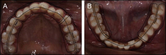
The intraoral scans were performed according to the manufacturer’s recommendations. In brief, the patient was seated upright, adequate moisture control was obtained with absorbent triangles (Dri-Angle; Dental Health Products, New Franken, Wis) and cheek retractors (OptraGate; Ivoclar Vivadent, Amherst, NY), and a light coating of titanium dioxide powder (3M ESPE) was applied to the patient’s teeth. The teeth were then scanned starting in the mandibular right quadrant and ending in the maxillary left quadrant ( Fig 2 ). The second and third molars were included in the scan, when present. Any voids in the scan were captured after the entire arch was scanned. A bite registration was obtained by scanning the buccal surfaces of the patient’s right premolars and first molars in centric occlusion. The scan was then electronically submitted to the manufacturer of the scanner for digital model fabrication. After the clinical procedures, each patient was asked to complete a specifically designed survey ( Supplementary Appendix ) to determine the preferred model acquisition method.
In addition to the intraoral scans performed on the patients, 5 pairs of plaster models were scanned using the Lava COS and an orthodontic model scanner (R700; 3Shape A/S, Copenhagen, Denmark) at a resolution of 20 μm. The inclusion criteria for the plaster models were identical to those described for the patients in the clinical part of the study. The rationale for this benchtop experiment was to assess the accuracy of the intraoral scanner relative to a high-resolution model scanner, excluding patient factors and potential confounders such as alginate distortion and shrinkage.
All digital models were received as stereolithographic files and reoriented before processing to achieve a consistent 3-dimensional (3D) orientation. Each pair of models (eg, maxillary arch digital model obtained with the intraoral scanner and the corresponding maxillary arch model obtained with alginate impressions model scanner) was digitally superimposed using emodel software (version 9.0; GeoDigm, Falcon Heights, Minn). To ensure that the superimposition was based solely on tooth features, interproximal papillae and the model base apical to the gingival margin were removed from the models that had been obtained with alginate impressions or the model scanner ( Fig 3 ). One model required segmentation of individual teeth for the software to perform tooth superimpositions. In the clinical part of the study, the teeth were individually segmented on the digital models generated from the alginate impressions. In the benchtop experiment, the teeth were individually segmented on the digital models generated from the model scanner. Third molars and a lone erupted second molar in an arch were not segmented because of software limitations; thus, all arches were segmented either from first molar to first molar or from second molar to second molar.
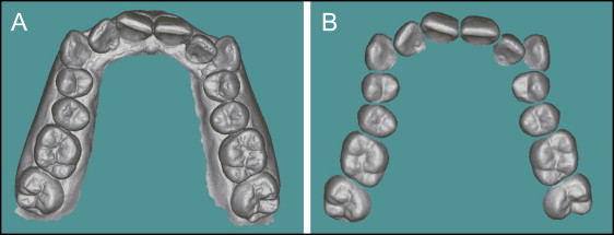
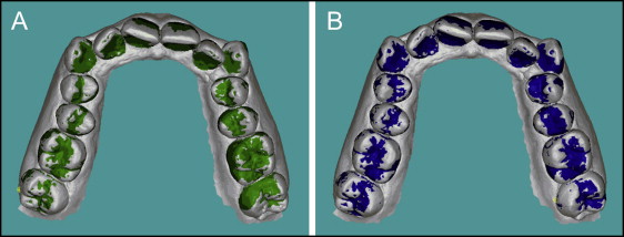
Each pair of models was superimposed using best-fit surface feature-based registration. Global arch registration of the model pairs was performed with an iterative closest-point algorithm to align the models according to the best fit for each full arch. Arch registration was completed by 50 transformations of iterative closest point matching at 1-mm surface increments using the software’s autosuperimposition function ( Fig 3 ) and was visually verified by the operator. After the full-arch registration, surface feature-based superimpositions of individual teeth were performed by 50 transformations of iterative closest point matching as detailed above ( Fig 4 ).
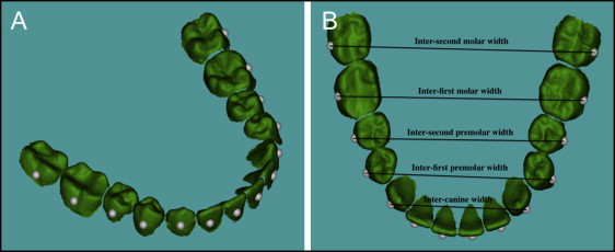
Differences in tooth positions between digital models obtained from intraoral scans and the alginate impressions or model scanner were quantified as distances between datum point locations. A datum point is a reference point on the surface of each segmented tooth that represents its 3D position. The datum point location was determined by calculating the centroid of each segmented tooth, transposing this point to the facial surface, and placing it on the occlusogingival midpoint of the crown ( Fig 5 ). The datum points were positioned on a 3D coordinate system, and their locations were measured when the arches were registered and when the teeth were individually superimposed. The differences in datum point positions from arch registration to individual tooth positions were quantified to the nearest 1 μm. Measurements included the differences in individual tooth positions in each plane of space, the differences in arch widths ( Fig 5 ), and the differences in arch lengths. Arch width measurements were grouped by tooth type: maxillary intermolar, interpremolar, and intercanine widths, and mandibular intermolar, interpremolar, and intercanine widths. Arch length was calculated as the length of a line connecting all datum points in a given arch.
Statistical analyses
Accuracy was assessed as the agreement between the digital models acquired using the intraoral scanner and the corresponding models that had been acquired with either the alginate impressions or the model scanner using the method described by Bland and Altman. Bias was computed as the average of the differences between the models. Calculation of the limits of agreement during the Bland-Altman analysis provided limits that contained 95% of the differences. Bland-Altman analyses were performed on differences in individual tooth positions in the transverse, sagittal, and vertical planes of space, as well as on differences in arch width and arch length.
Mean values and standard deviations of the times required for impressions and intraoral scans were calculated, and the differences were tested for statistical significance using the Student t test after the data had been tested for normality (Shapiro-Wilk test). A linear regression analysis was used to evaluate whether the scan times changed with the number of scans performed. Descriptive statistics were used to compare patient acceptance between the model acquisition methods. Statistical analyses were performed using SAS software (version 9.4 for Windows; SAS Institute, Cary, NC). P values of less than 0.05 were considered statistically significant.
Results
The relative accuracy in the transverse, sagittal, and vertical planes of space of digital models acquired from patients with the Lava COS is reported in Table II . The biases—ie, the average differences in individual tooth positions between the models acquired with the intraoral scan and the corresponding models acquired with alginate impressions—ranged from −0.05 to 0.21 mm in the maxilla and from −0.04 to 0.11 mm in the mandible. The average biases for individual tooth positions were 0.02 mm for maxillary teeth and 0.01 mm for mandibular teeth, the average biases for arch widths were 0.18 mm in the maxillary arch and 0.09 mm in the mandibular arch, and the average biases for arch lengths were −0.38 mm in the maxillary arch and −0.21 mm in the mandibular arch. The largest bias for individual tooth positions was found for the maxillary second molars in the transverse plane of space (0.21 mm), and the largest bias for arch width was found for maxillary intermolar width (0.32 mm).
| Direction | n | Bias (mm) | Lower limit of agreement (mm) | Upper limit of agreement (mm) | Agreement interval width (mm) | |
|---|---|---|---|---|---|---|
| Maxillary | ||||||
| Second molars | Transverse | 28 | 0.21 | −0.08 | 0.50 | 0.58 |
| Sagittal | 28 | 0.04 | −0.15 | 0.22 | 0.37 | |
| Vertical | 28 | −0.02 | −0.25 | 0.21 | 0.46 | |
| First molars | Transverse | 30 | 0.10 | −0.13 | 0.34 | 0.47 |
| Sagittal | 30 | 0.00 | −0.13 | 0.13 | 0.26 | |
| Vertical | 30 | 0.02 | −0.20 | 0.25 | 0.45 | |
| Second premolars | Transverse | 30 | 0.06 | −0.11 | 0.24 | 0.35 |
| Sagittal | 30 | 0.04 | −0.08 | 0.16 | 0.24 | |
| Vertical | 30 | −0.02 | −0.19 | 0.14 | 0.33 | |
| First premolars | Transverse | 30 | 0.04 | −0.10 | 0.18 | 0.28 |
| Sagittal | 30 | 0.02 | −0.12 | 0.16 | 0.28 | |
| Vertical | 30 | −0.04 | −0.21 | 0.13 | 0.34 | |
| Canines | Transverse | 30 | 0.06 | −0.09 | 0.20 | 0.29 |
| Sagittal | 30 | −0.04 | −0.23 | 0.15 | 0.38 | |
| Vertical | 30 | −0.01 | −0.21 | 0.19 | 0.40 | |
| Lateral incisors | Transverse | 30 | 0.05 | −0.10 | 0.20 | 0.30 |
| Sagittal | 30 | 0.01 | −0.16 | 0.17 | 0.33 | |
| Vertical | 30 | 0.00 | −0.16 | 0.16 | 0.32 | |
| Central incisors | Transverse | 30 | 0.01 | −0.08 | 0.10 | 0.18 |
| Sagittal | 30 | −0.05 | −0.17 | 0.06 | 0.23 | |
| Vertical | 30 | 0.00 | −0.19 | 0.19 | 0.38 | |
| Intermolar width | 29 | 0.32 | −0.22 | 0.85 | 1.07 | |
| Interpremolar width | 30 | 0.11 | −0.19 | 0.40 | 0.59 | |
| Intercanine width | 15 | 0.11 | −0.06 | 0.28 | 0.34 | |
| Arch length | 15 | −0.38 | −0.75 | −0.02 | 0.73 | |
| Mandibular | ||||||
| Second molars | Transverse | 28 | 0.11 | −0.09 | 0.30 | 0.39 |
| Sagittal | 28 | 0.04 | −0.20 | 0.29 | 0.49 | |
| Vertical | 28 | 0.06 | −0.22 | 0.33 | 0.35 | |
| First molars | Transverse | 30 | 0.06 | −0.06 | 0.18 | 0.24 |
| Sagittal | 30 | 0.01 | −0.12 | 0.14 | 0.26 | |
| Vertical | 30 | −0.04 | −0.22 | 0.13 | 0.35 | |
| Second premolars | Transverse | 30 | 0.03 | −0.05 | 0.11 | 0.16 |
| Sagittal | 30 | −0.01 | −0.12 | 0.09 | 0.21 | |
| Vertical | 30 | 0.00 | −0.19 | 0.19 | 0.38 | |
| First premolars | Transverse | 30 | 0.01 | −0.07 | 0.10 | 0.17 |
| Sagittal | 30 | −0.03 | −0.17 | 0.11 | 0.28 | |
| Vertical | 30 | 0.02 | −0.15 | 0.18 | 0.33 | |
| Canines | Transverse | 30 | 0.03 | −0.07 | 0.13 | 0.20 |
| Sagittal | 30 | −0.01 | −0.10 | 0.08 | 0.18 | |
| Vertical | 30 | 0.01 | −0.12 | 0.14 | 0.26 | |
| Lateral incisors | Transverse | 30 | −0.02 | −0.15 | 0.10 | 0.25 |
| Sagittal | 30 | 0.00 | −0.11 | 0.10 | 0.21 | |
| Vertical | 30 | 0.02 | −0.09 | 0.14 | 0.23 | |
| Central incisors | Transverse | 30 | −0.01 | −0.12 | 0.09 | 0.21 |
| Sagittal | 30 | 0.01 | −0.08 | 0.10 | 0.18 | |
| Vertical | 30 | 0.02 | −0.10 | 0.13 | 0.23 | |
| Intermolar width | 29 | 0.17 | −0.14 | 0.48 | 0.62 | |
| Interpremolar width | 30 | 0.04 | −0.10 | 0.18 | 0.28 | |
| Intercanine width | 15 | 0.06 | −0.09 | 0.21 | 0.30 | |
| Arch length | 15 | −0.21 | −0.65 | 0.23 | 0.88 |
The accuracy of the digital models acquired in the benchtop experiment with the Lava COS is reported in Table III . The biases for individual tooth positions ranged from −0.07 to 0.11 mm in the maxilla and from −0.06 to 0.03 mm in the mandible. The average biases for individual tooth positions were 0.01 mm for maxillary teeth and −0.01 mm for mandibular teeth, the average biases for arch widths were 0.10 mm in the maxillary arch and −0.06 mm in the mandibular arch, and the average biases for arch lengths were −0.25 mm in the maxillary arch and −0.07 mm in the mandibular arch. Similar to the clinical part of the study, the largest bias for individual tooth positions was found for the maxillary second molars in the transverse plane of space (0.11 mm), and the largest bias for arch width was found for maxillary intermolar width (0.17 mm).


