Fig. 3.1
(a) Usual dimensions and form of a panoramic focal trough. (b) The slice thickness does not cover the entire volume of the maxillary sinus
If one considers that the average depth of the maxillary sinus is approximately 40–50 mm, panoramic image could ignore pathological formations of posterior topography or in the internal sinus parts (“false negative”) (Fig. 3.1b).
That is why it is considered that panoramic image does not allow reliable or complete radiological representation of the maxillary sinuses even if it is the starting point of every sinus examination (Chomenko 1985).
On another side, it has been established that panoramic views of the posterior maxilla will underestimate the amount of bone available for implant placement and will therefore overestimate the number of clinical situations requiring SFE.
3.2.3 The Waters’ View
Specialized skull views are usually the next step in the sinus exploration. The standard series of conventional plain film techniques include the occipitomental (Waters), lateral, submentovertex, and Caldwell (PA) skull views.
The most interesting one remains the Waters projection. It is optimal for visualization of the maxillary sinuses, especially to compare internal radiopacities, as well as the frontal sinuses and ethmoid air cells. If the Waters’ view is made with the mouth open, the sphenoid sinuses may also be visualized. Table 3.1 shows the differences between periapical, panoramic, and Waters projections (Chomenko 1985).
Table 3.1
Sinus area best demonstrated by panoramic, Waters, and periapical projections (Chomenko 1985)
|
View
|
Sinus area best seen
|
|---|---|
|
Periapical (or occlusal films)
|
Relationship of teeth to sinus floor.
|
|
Panoramic
|
Inferior wall (floor), teeth-sinus relationship.
|
|
Waters
|
Medial wall, boundary of anterior and posterior walls, medial and lateral extents.
|
Although the Waters’ view visualizes the maxillary sinus better than any other view, it fails to delineate the anterior and posterior sinus walls because they overlap. Also, the relationship of the sinus floor to teeth is poorly demonstrated. Table 3.2 is a comparison between panoramic and Waters’ view (Chomenko 1985).
Table 3.2
Comparison of panoramic and Waters’ view for maxillary sinuses (Chomenko 1985)
|
Panoramic
|
Waters’ view
|
|---|---|
|
Actual anatomic boundaries of sinus not seen
|
Lateral and medial walls form, respectively, lateral and medial sinus outlines on film
|
|
Anterior, posterior, and medial walls not seen
|
Lateral wall distinguished from medial wall
|
|
Tooth-sinus relationship shown clearly
|
Tooth-sinus relationship obscured
|
|
Shadow superimposition of nasal structure
|
No superimposition of nasal structure
|
|
Radiographic variation between right and left sinuses considerable
|
Radiographic comparison between right and left sinuses possible
|
|
Anteroposterior aspect of sinus depicted (standard position)
|
Mediolateral aspect of sinus depicted
|
3.2.4 Computed Tomography and Cone Beam Computed Tomography
Computed tomography (CT) is replacing conventional tomography for investigations and evaluation of sinus diseases because it offers considerable advantages over them. It is now considered an essential presurgical diagnostic method.
Because CT provides multiple sections through the sinuses in different planes with high-resolution images, they contribute significantly to delineate the extent of disease and the final diagnosis. CT examination is appropriate to determine the extent of disease, for superior visualization of the ostiomeatal complex (the region of the ostium of the maxillary sinus and the ethmoidal ostium) and nasal cavities, as well as for demonstrating any reaction in the surrounding bone to sinus disease.
Although CT is considered as the “gold standard” in imaging for visualization of the maxillary sinus, since the late 1990s, cone beam computed tomography (CBCT) is gaining increasing popularity in this respect (Bremke et al. 2009; Cakli et al. 2012; Fatterpekar et al. 2008; Ziegler et al. 2002). In implant dentistry, recent guidelines recommend the use of CBCT for three-dimensional treatment planning, especially prior to SFE – for evaluating both residual alveolar and sinus conditions (Benavides et al. 2012; Harris et al. 2012).
CBCT provides a three-dimensional volumetric dataset with an isotropic resolution of 300/400 μm. The geometric accuracy and the resolution are sufficient for clinical usage and comparable to a CT image with however a lower dose than that of a CT examination of the same region.
3.2.5 Magnetic Resonance Imaging
MRI provides superior visualization of the soft tissues, especially the extension of infiltrating neoplasms into the sinuses or surrounding soft tissues, or the differentiation of retained fluid secretions from soft tissue masses in the sinuses.
3.3 What to Look for on a CBCT Examination?
If a SFE procedure is indicated, a variety of anatomical factors may influence the decision, design of the lateral window and choice of graft material. Information on bone density, bone cortical walls, and bone resorption in the alveolar processes is important for planning functionally and aesthetically optimal prosthetic treatment. Information on associated dental-sinus pathologies is also important.
3.3.1 Sinus Condition
The first thing to look at is the density of the sinus. A normal sinus will appear as a low-density homogenous cavity.
3.3.2 Ostium
The maxillary sinus communicates with the homolateral nasal fossa by means of a natural ostium located posterosuperiorly on the medial surface (Fig. 3.2).
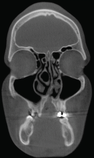
Fig. 3.2
The osteomeatal complex
Determining the position and the integrity of the osteomeatal complex is essential when planning SFE procedures.
The mesiobuccal and medial bone walls are the ones most often involved in SFE. An accessory ostium may sometimes be found on the medial wall. When this occurs, it should be identified before any maxillary sinus-elevation procedure is performed, to avoid detaching the mucosa up to this point.
Unfortunately, a small “field of view” (FOV) is often used to visualize only the inferior part of the maxillary sinus and its relation to the remaining bone where implants will be placed. Guidelines suggest that extending the FOV to include the osteomeatal complex may be justified to avoid postoperative complications resulting from a compromised drainage system (Harris et al. 2012). An adequate FOV in CBCT technique should allow precise evaluation of its numerous components, revealing any irregularities in development (e.g., conchae bullosa, septum deviation, or inflammation involving the maxillary sinus ostium) (Fig. 3.2). Respecting the structure of the ostium is essential for a successful SFE.
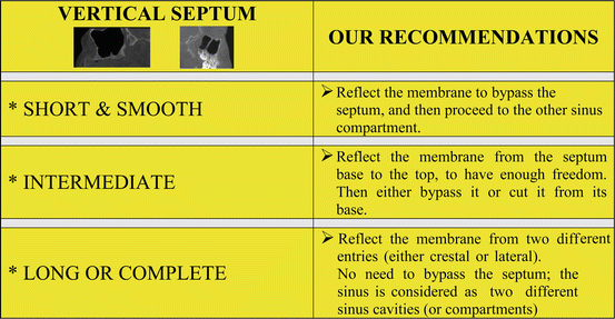
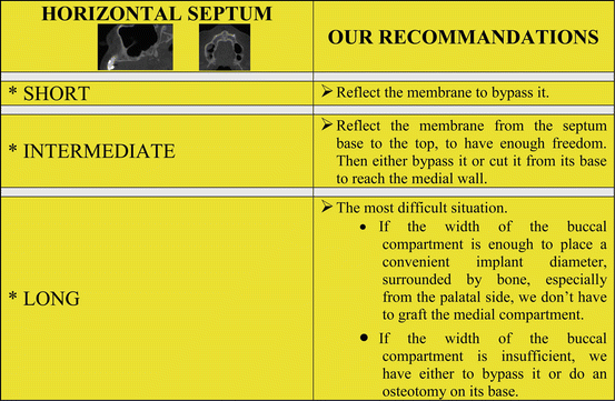
3.3.3 Septa
Septa (Fig. 3.3) are the most frequent anatomic variations within the maxillary sinus. They were first described by Underwood in 1910 and, therefore, have sometimes been referred to as Underwood’s septa (Underwood 1910).
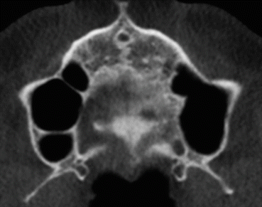
Fig. 3.3
Axial view – double septa in the right maxillary sinus
It has been reported that they increase the risk of sinus membrane perforation during SFE. If septa are present on the sinus floor, they can complicate both the inversion of the bone plate and elevation of the sinus membrane. One of the possible complications associated with perforation of the sinus membrane is the development of maxillary sinusitis (Quiney et al. 1990; Ueda and Kaneda 1992; Zimbler et al. 1998).
If septa are encountered on the antral floor, some authors recommend cutting them with a narrow chisel and removing them with a hemostat, so the bone graft can be placed over the entire antral floor without interruption (Boyne and James 1980). Therefore, a modification of the conventional surgical technique is required when septa are present (Betts and Miloro 1994).
3.3.4 Vascularization
Three arteries supply blood to the maxillary sinus: the infraorbital artery, the posterior lateral nasal artery, and the posterior superior alveolar artery (PSAA). While their presence should be investigated to avoid hemorrhages during SFE, severe hemorrhages tend to be rare, as the main arteries do not run inside the surgical area.
The progressive atrophy of the alveolar ridge with age and tooth loss results in changes in the blood supply to that area. The maxilla is very densely vascularized in young, dentate individuals. In older, edentulous populations, the number of vessels and vessel diameter decreases, while the tortuosity of the vessels increases (Elian et al. 2005; Ulm et al. 1995; Watzek et al. 1993).
To confirm the radiographic presence of the canal, one must examine the axial and coronal images. In coronal views, the PSAA appears as a circular or oval low-density structure that is fully or partially embedded within the thickness of the lateral wall of the maxillary sinus. It has to be seen along the sinus border while scrolling the axial views (Noujeim et al. 2014).
The radiographic location can be divided in three categories (Fig. 3.4):
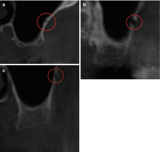
Fig. 3.4
Coronal view – The posterior superior alveolar artery. (a) PSAA is located between the Schneiderian membrane and the osseous wall. (b) PSAA is situated within the thickness of the osseous wall. (c) PSAA is on the external aspect of the lateral wall. (a–c) Circle denotes structure
1.
PSAA is located between the Schneiderian membrane and the osseous wall.
2.
It is situated within the thickness of the osseous wall.
The canal can radiographically be identified in over 50 % of examined CT images, equally between the right and left side. The canal is between 1 and 2 cm superior to the alveolar crest (average height = 16.4 mm) (Noujeim et al. 2014). Different studies achieve almost the same results (Elian et al. 2005; Ilgüy et al. 2013).
Table 3.5 proposes recommendations based on some parameters of PSAA.
Table 3.5
Influence of the posterior superior alveolar artery on the SFE procedure
|
The posterior superior alveolar artery
|
|
|---|---|
|
Height
Influence the design of the window
|
Adjust within the limitations of the basic principles of window design surgery
The design should be appropriate enough to reflect the membrane, contain the grafting material, and place an adequate implant when indicated
|
|
Location
Adjust the height of the window trap
|
Intraosseous: the separation is better with the piezoelectrical device to avoid bleeding
Extraosseous: the reflection is possible manually, when performed carefully
|
|
Diameter
|
Small: minimal risk of bleeding
|
|
Big: the risk of bleeding is higher
|
|
3.3.5 The Schneiderian Membrane
The Schneiderian (mucous) membrane lines the inner walls of the sinus and in turn is covered by pseudo-stratified columnar ciliated epithelium. Serum-mucosa glands are located in the lamina directly underneath, especially next to the ostium opening. The sinus membrane appears to be the main carrier of bone reformation after SFE, as multiple experimental studies suggested (Troedhan et al. 2012).
Normally, the thickness of the Schneiderian membrane varies from 0.13 to 0.5 mm (Tiziano 2012). However, inflammation or allergic phenomena may cause its thickening, either generally or locally (Fig. 3.5). In such cases, it may be necessary for an ENT to restore the sinus to a physiologic state before SFE can be carried out (see Chap. 4).
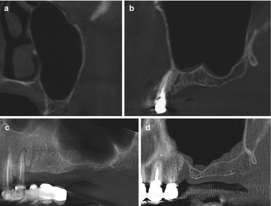
Fig. 3.5
The Schneiderian membrane appearance. (a) Normal mucosa, (b) flat mucosal thickening, (c) spherical thickening, and (d) irregular thickening
Mucosal thickening is the most frequently observed abnormality (66.0 %). It is generally associated with some kind of irritation, such as odontogenic pathology or allergic phenomena. Nonvital posterior maxillary teeth, periodontal abscesses, retained roots, embedded or impacted teeth, extensively carious teeth, and oroantral fistulae could be etiological factors in pathologies of odontogenic origin (Rege et al. 2012).
During osteotomy, the membrane should not be perforated:
-
By mechanical burs
-
By uncontrolled use of the piezoelectrical devices
Table 3.6 shows the influence of the sinus membrane thickness on SFE.
Table 3.6
Influence of the sinus membrane thickness on the SFE procedure
|
Thick membrane
|
Thin membrane
|
|---|---|
|
Reduced risk of membrane perforation during both reflection and osteotomy steps
|
During reflection, caution is required to liberate progressively the membrane in all directions rather than proceeding in one direction
|
3.3.5.1 Mucocele
Mucoceles of maxillary sinus are fairly rare (3–10 %). They have been described in association with neoplasia, trauma, surgery, inflammatory process (e.g., cystic fibrosis), and congenital abnormalities. Mucoceles are consequent to an obstruction of the sinus ostia and drainage pattern, with accumulation of mucus within the sinus cavity. Continual accumulation causes it to expand from the pressure. Sinus walls may be remodeled or completely de-ossified and eroded (Sreedharan et al. 2011).
The appearance of mucoceles is well described. Their image is a smooth expansile low-attenuation lesion arising in the maxilla. The majority is homogenous and isodense with the brain and typically shows a rounded bony outline (Fig. 3.6). Most mucoceles do not show contrast enhancement, and in fact, the administration of contrast medium is rarely necessary.
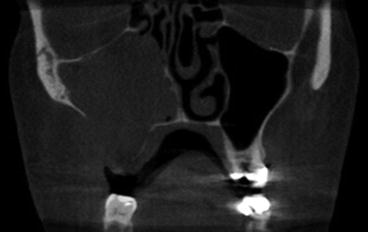
Fig. 3.6
Mucocele
An opaque maxillary sinus without bone erosion invites the diagnosis of sinusitis, retention cysts, and antrochoanal polyps. With expansion and bone destruction, the differential diagnosis include malignant conditions like adenoid cystic carcinoma, plasmacytoma, rhabdomyosarcoma, lymphoma, schwannoma, and tumors of dental origin (Sreedharan et al. 2011).
The recommended treatment for maxillary sinus mucoceles with no extension to soft tissues of the cheek is endoscopic evacuation with wide middle meatal antrostomy. A Caldwell-Luc approach may be needed for mucoceles that have extended into facial soft tissues, pterygomaxillary fossa, or those which have not been satisfactorily evacuated by endoscopic sinus surgery (Har-El 2001).
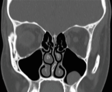
3.3.5.2 Mucous Retention Cyst
Mucous retention cysts of the maxillary sinus are an asymptomatic lesion incidentally found during the examination of images. On radiographs, they are radiopaque dome-shaped structures with a distinctly rounded edge (Fig. 3.7). They are slow-growing lesions, but mucosal and cortical integrity is preserved. Their etiology is unclear.
Stay updated, free dental videos. Join our Telegram channel
VIDEdental - Online dental courses


