The purposes of this study were to apply the latest developments in additive manufacturing (AM) construction and to evaluate the effectiveness of these computer-aided design and computer-aided manufacturing (CAD/CAM) techniques in the production of dental appliances. In addition, a new method of incorporating wire into a single build was developed. A scanner was used to capture 3-dimensional images of Class II Division 1 dental models that were translated onto a 2-dimensional computer screen. Andresen and sleep-apnea devices were designed in 3 dimensions by using FreeForm software (version 11; Geo Magics SensAble Group, Wilmington, Mass) and a phantom arm. The design was then exported and transferred to an AM machine for building.
Computer-aided design/computer-aided manufacturing/additive manufacturing (CAD/CAM/AM) scanning systems have been successfully introduced in dentistry. Researchers have used this technology as a tool for orthodontic diagnosis and treatment planning for determining the position of impacted maxillary canines and for the fabrication of occlusal splints. However, CAD/CAM/AM innovations have not been used successfully on a wide scale for removable orthodontic appliances.
Sassani and Roberts reported that it was possible to use CAD/CAM/AM techniques to build base plates of orthodontic appliances, but they stated that it was not possible to incorporate wires into the built parts. However, in this study, we discuss a method to accomplish this.
The technology mentioned above has been used in orthodontic treatments such as the invisible orthodontic appliance fabricated without metal wires or brackets (Align Technology, Santa Clara, Calif) and in producing customized lingual brackets. Recently, Wiechmann et al used this computer-based technology to make connectors for Herbst appliance hinges to custom lingual brackets, and the authors of a more recent study used this technique for a digital titanium Herbst appliance.
Because of the lack of application in general to removable appliances, the aims of this study were to apply new methods of producing dental appliances with wires and hinges by using CAD/CAM/AM based techniques and to evaluate these. Andresen and sleep-apnea appliances were chosen. Although an Andresen appliance is rarely used, it provides a clear illustration for the inclusion of wire into a build that is straightforward. A sleep-apnea device shows where 4 coordinating hinges can be studied. Both devices were produced in a single build.
Material and methods
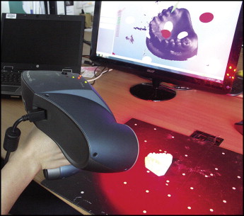
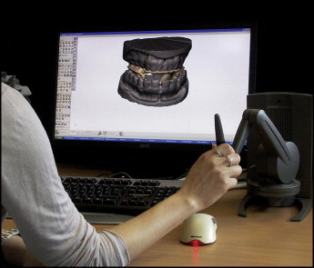
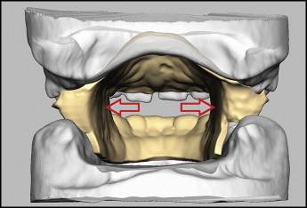
Opposing Class II case models suitable to be treated with Andresen and sleep-apnea removable devices were scanned by a hand-held laser sensor (HandyScan 3D; Creaform, Lévis, Québec, Canada) ( Fig 1 ). Laser lines were projected from the scanner onto the surface of each model to produce a 3-dimensional image from a “point cloud.” The software automatically transformed the point cloud into a stereolithographic facet file, shown as it appears on a screen ( Fig 2 ).
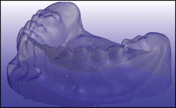
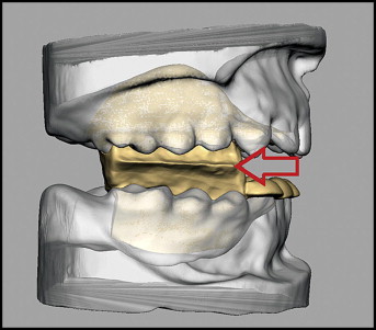
The scanner was moved around the casts by hand to produce a clear and complete 3-dimensional surface in STereoLithography (STL), a defacto file type used in AM ( Fig 3 ), with a minimum of missing data.
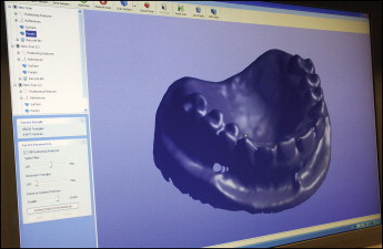
The data were processed, and the STL files were generated by using the proprietary scanner software (VX elements, version 2.1; Creaform). The appliances were designed with specialist CAD software (FreeForm Modeling Plus, version 11; Geo Magics SensAble Group, Wilmington, Mass), in conjunction with a Phantom Desktop (Geo Magics SensAble Group) (haptic) arm ( Fig 4 ). This apparatus allowed appliances to be “built” on scans of a patient’s cast in a virtual environment.
The software enables the design of complex, nongeometric forms and is ideal for designing anatomically based devices. It has various tools to accomplish specific functions. Some tools are used for building, and others are used for trimming and shaping the constructed parts. The Phantom device works as a 3-dimensional mouse because it mimics the work of a dental technician, enabling the design and construction of the appropriate appliances similarly to the conventional method. The operator can feel force feedback sensations during the process.
Before the virtual build, it was necessary to create a Class I molar relationship or achieve this as closely as possible. This relationship was accomplished by posturing the mandible forward, until a Class I molar relationship was obtained and the vertical opening between the opposing premolars was 4 to 5 mm at the lingual cusps.
The labial inclination of the maxillary central incisors was selected as a reference for the “path of insertion” of the appliance onto the upper model. Undercuts on both virtual models were detected and eliminated virtually automatically by using the “extrude-to-plane” tool. The files were then saved as “buck” files, which meant that the models were protected and could not be changed.
The following is a brief description of the design process for each appliance.
For the Andresen, a 2-mm layer was applied to the upper and lower models with capping on the mandibular incisors. Palatal coverage was made by selecting the required area with a cursor and offsetting a 2-mm thickness to form the plate. Upper and lower plates extended to the first molars. Capping was 1 mm thick on the mandibular anterior teeth to prevent proclination and overeruption. The thickness of the appliance was set at 2 mm to withstand occlusal forces and patient handling. The virtual material so formed is termed “clay,” and it is added and shaped in a similar way to physical wax. It was necessary to add clay in some areas of the appliance to make the surfaces smooth and to form junctions of 2 surfaces continuous to each other. Borders were smoothed.
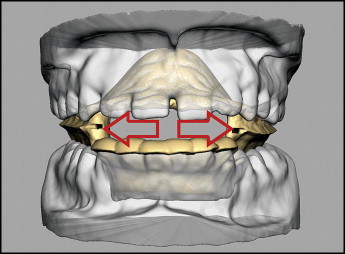
Finally, the occlusal surfaces of the opposing offset clay areas were connected to produce a 1-piece “monoblock” at the lingual surfaces of the teeth extending to the middle of the occlusal surfaces ( Fig 5 ).
These blocks were attached to the plates, and the junctions were smoothed with the “sculpting” and “smooth” tools. The middle distances of the blocks were stretched buccally by using the “smudge” tool up to the outline of the buccal surfaces to form a sharp “intermaxillary edge.” The blocks were cleared from the mandibular teeth to permit upward and forward eruption ( Fig 6 ).
To allow wire to be inserted in the physical build, a square section tube (1.25 × 1.25 mm) on either side of the appliance was created. Each tube consisted of 2 parts. The first part was horizontal, 15 mm in length and 1 mm from the lingual walls of the intermaxillary blocks, and was located in the maxillary part with its lower border at the level of the intermaxillary edge. The second part was vertical, projecting into the maxillary part, and 5 mm in length. The first part was at right angles to the second part, and these were connected at a point between the second premolar and the first molar. These tubes were made so that the retentive part of a 0.9-mm hard stainless steel wire labial bow could be inserted, as shown in Figure 7 .