Fig. 9.1
Design of C-tube. (a) I-type. (b) T-type C-tube with short neck. (c) T-type C-tube with long neck
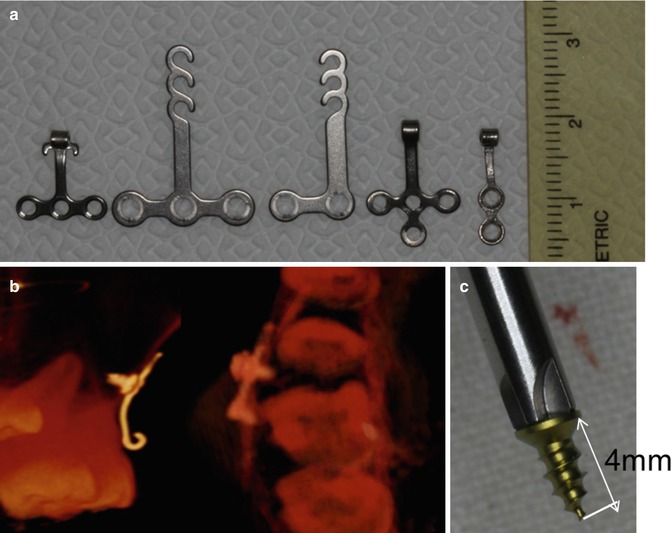
Fig. 9.2
(a) Modifications of the design. (From left to right) Basic T-type, T-type SAS system, L-type SAS system, hookless T-type, and hookless I-type. (b, c) Although miniplate anchoring screws penetrated into the sinus space, C-tube was successfully stabilized and exerted sufficient absolute anchorage without any complications due to the short length (less than 4 mm)
In the recent research of Lee et al., the C-tube showed excellent data of 96 % survival rates [7]. Even with minor complications, C-tube resulted in high success ratio. The versatile C-tube possesses many advantages for clinicians and patients with minimum invasive minor surgical placement. For the successful survival rate, maintenance of good oral hygiene is most important, and experiences of clinicians rank in the second place. Kim et al. suggested in a journal that C-tube placement is very safe with the miniplate anchoring screws (MPAS) and the stability is maintained even with less-than-ideal placement by MPAS [8]. Due to the small size of MPAS, close proximity of the root contact and root perforated MPAS posed no harm to dentition and served as stable temporary skeletal anchorage devices (TSADs). Cautions to avoid these complications are necessary, but C-tube is definitely a good option of TSADs for patients and clinicians.
C-tube is useful in places where placement of conventional TSAD faces difficulty such as extremely narrow interradicular space, extended maxillary sinus space, severe alveolar bone loss, and dilacerated root (Fig. 9.3). The total length of fixation screw is 4 mm, which means it will actually penetrate about 2–3 mm into the alveolar bone for anchorage, but strong enough to resist orthodontic force application. As in Fig. 9.4, in cases of very narrow interradicular space and pneumatization of sinus floor to the roots of posterior teeth, C-tube placement certainly can be a legible option to replace the mini-implant. Figure 9.3c shows the fixation screw penetration into the sinus wall, and it is clearly shorter than the C-implant placement on the other side, Fig. 9.3b.
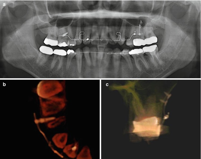
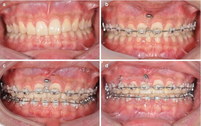
Fig. 9.3
It is very difficult to safely place conventional mini-implant in this patient where interradicular space is extremely narrow and maxillary sinus had extended (a). C-implant was placed between the upper right second premolar and first molar (b) and I-type C-tube was placed between the mesiobuccal and distobuccal root of the upper left first molar (c). Sufficient stability of the C-tube was obtained from cortical bone of the sinus wall
Fig. 9.4
Intrusion of upper dentition with C-tube. (a) Initial photo. (b) C-tube was placed between the right and left upper central incisor. (c) Intrusion mostly occurred on central incisors. (d) After upper dentition was sufficiently intruded, dental midline was corrected by connecting elastics between C-tube and extension hook on the distal of the upper right canine
Narrow interradicular space is common findings in the anterior area of both the upper and lower jaws, and the C-tubes can be successfully placed into these particular areas to apply intrusive orthodontic forces (Figs. 9.4 and 9.5). When patients have stable posterior occlusion but with deep overbite, intrusion of the anterior teeth can solve the problem. However, finding the wide-enough interradicular space for conventional mini-implants is very rare in the anterior legion, and additionally, the buccal frenums often interfere with the placement. The C-tube can be anchored underneath the movable mucosa, and the neck and head portion can be exposed through the attachable gingiva or the junction of the movable and attached gingiva to control gingival inflammation. Also, this allows bypassing the frenums during placement. With these absolute skeletal anchorages, the intrusive orthodontic force of the anterior teeth can be achieved, and with extension of a hook, midline discrepancy correction can be achieved in Fig. 9.4d.
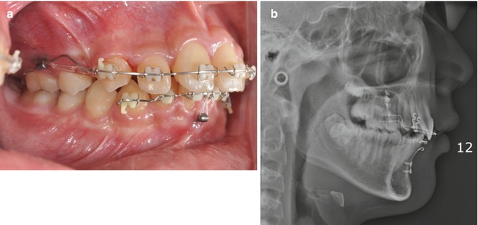
Fig. 9.5
(a) Intrusion of the lower six anteriors and en masse retraction of the upper six anteriors with C-tubes after extraction of the upper first premolars. (b) Lower C-tube was adapted to the curvature of the symphysis
Another advantage of C-tube is easy adjustment of the tube according to the location of insertion. The titanium possesses enough rigidity to withstand orthodontic force application without distortion, but moldable enough to fit the curvatures of recipient bone contour. It is easily bent with a plier and clinicians can adapt to different locations with no trouble. Notice the curvature of the C-tube in Fig. 9.5b that is following the mandibular symphysis contour. When attempting to achieve intrusion of the teeth, the replacements of the TSADs are often needed to achieve the expected amount of intrusion. But with a C-tube, the drawbacks can be solved with just a weingart plier to bend the C-tube neck portion to gain more length for the intrusion force [9]. Furthermore, the C-tube neck portion can be twisted off to get detached from the anchoring portion leaving the fixation portion in place [10].
C-tube also serves as an excellent alternative for immediately replacing loosened TSADs. C-tube acts as a stable anchorage device enabling en masse retraction. Miniscrew loosening occurred before planned retraction of the upper arch completed, and for the immediate replacement of TSAD, C-tube was performed (Fig. 9.6). First, check where the fixation screws should be placed and one horizontal incision made on movable mucosa. By stretching the movable mucosa, enough access for the two fixation screws was made. By connecting the removed screw hole to the incision line by a tunneling technique, the C-tube head can be placed out of the screw hole in attached gingiva (Fig. 9.7). Simple sutures are placed for the closure of horizontal incision, and C-tube placement is completed (Fig. 9.8). The C-tube placement is minimally invasive and pain medication will alleviate the discomfort with a procedure.
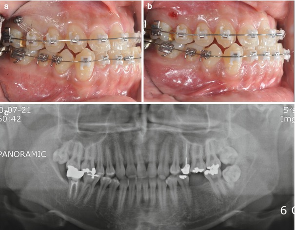
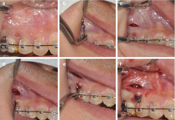
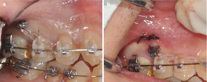
Fig. 9.6
Immediate replacement of loosened TSAD with C-tube. (a) Loosened TSAD between the upper right second premolar and first molar. (b) TSAD was removed. (c) Panoramic x-ray
Fig. 9.7
Replacement protocol. (a) Minor incision for entry to embed screw holes. (b) Preoperative try-in of C-tube. (c) Horizontal incision for placing fixation screws. (d) Tunneling through the entry incision to the horizontal incision. (e) Insertion of C-tube to the entry incision. (f) After placing fixation screws
Fig. 9.8
(Continued) (a) Before removing loosened TSAD. (b) Replacing with C-tube
For the removal of the C-tube, it is exact reversal of the insertion process. When you are removing the C-tube after usage, first estimate where the fixation screws are located according to the shape of it (Fig. 9.9) or palpate the location with an explorer under local anesthesia (Fig. 9.11a). Then, make a vertical incision or horizontal incision to access and remove the fixation screws. For I-type C-tube, connecting the incision from the fixation screw to the neck is not necessary as seen in Fig. 9.10 because the fixation portion can be easily pulled out through the hole of the C-tube neck part. However, for the T-type or modified T-type C-tube, it is rather easier to extend the incision to the neck to ease the removing process of the C-tube (Figs. 9.10 and 9.11). Finally, simple sutures can close the incision.
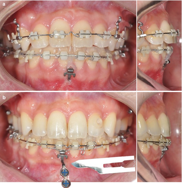
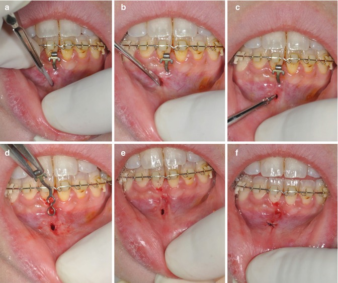
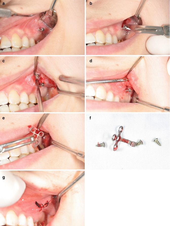
Fig. 9.9
Removal of the C-tube. Trace the location of the fixation screws by palpating the mucosa or investigating the shape of the screw
Fig. 9.10
Removal of I-type C-tube. (a) Making a short incision on the expected location of the fixation screw. (b) Blunt dissection with periosteal elevator. (c) Removing fixation screw. (d) Pulling the C-tube out of the mucosa. (e) After removal of the C-tube. (f) Single interrupted suture is sufficient to close the incision
Fig. 9.11
Removal of T-type C-tube. (a) Initial photo. (b, c) Incisions were made to disclose fixation screws. (d) Fixation screws were unscrewed. (e, f) T-type C-tube was removed. (g) Sutured
Stay updated, free dental videos. Join our Telegram channel
VIDEdental - Online dental courses


