Introduction
The aims of this study were to evaluate the effects of rapid palatal expansion on the craniofacial skeleton of a patient with unilateral cleft lip and palate (UCLP) and to predict the points of force application for optimal expansion using a 3-dimensional finite element model.
Methods
A 3-dimensional finite element model of the craniofacial complex with UCLP was generated from spiral computed tomographic scans with imaging software (Mimics, version 13.1; Materialise, Leuven, Belgium). This model was imported into the finite element solver (version 12.0; ANSYS, Canonsburg, Pa) to evaluate transverse expansion forces from rapid palatal expansion. Finite element analysis was performed with transverse expansion to achieve 5 mm of anterolateral expansion of the collapsed minor segment to simulate correction of the anterior crossbite in a patient with UCLP.
Results
High-stress concentrations were observed at the body of the sphenoid, medial to the orbit, and at the inferior area of the zygomatic process of the maxilla. The craniofacial stress distribution was asymmetric, with higher stress levels on the cleft side. When forces were applied more anteriorly on the collapsed minor segment and more posteriorly on the major segment, there was greater expansion of the anterior region of the minor segment with minimal expansion of the major segment.
Conclusions
The transverse expansion forces from rapid palatal expansion are distributed to the 3 maxillary buttresses. Finite element analysis is an appropriate tool to study and predict the points of force application for better controlled expansion in patients with UCLP.
Highlights
- •
In unilateral cleft lip and palate patients, asymmetric stress distribution results from transverse expansion forces.
- •
Stress at the body of the sphenoid bone, cleft side, is 1.5 times greater than at the normal side.
- •
For more expansion of the minor segment, apply expansion forces anterior to it, posterior to the major segment.
- •
In anterior and posterior crossbite patients, apply expansion force posteriorly to both segments.
Cleft lip and palate (CLP) is the most common congenital defect involving the face and jaws; about 1 child in 700 children is born with the condition. Embryologic studies show that failure of fusion between the medial and nasal processes with the maxillary processes leads to clefting of the lip and palate. The cleft disrupts the structural integrity of the palate and results in mediolingual rotation of the minor segment of the maxilla. The collapsed minor segment is a common clinical feature in patients with unilateral CLP (UCLP) and is thought to be due to the molding influence of the surrounding facial soft tissues. It often results in a constricted palatal arch and severe anterior crossbite with or without a posterior crossbite that is isolated to the cleft side.
Anterolateral expansion of the minor segment is required to correct the transverse discrepancy from the collapsed minor segment and to achieve an ideal arch form. Palatal expansion devices, such as the 4-banded quad-helix, fan-type expander, and slim-line expander, are used to achieve anterior expansion. However, anatomic differences that result from the cleft and the asymmetric nature of the crossbite in patients with UCLP often make more expansion necessary in the anterior than in the posterior palate. Typical palatal expansion devices, normally used for non-CLP patients, correct the maxillary deficiency by applying transverse orthopedic forces and expanding the palate in the molar region. They do not target the problem area that is unique to patients with UCLP.
Rapid palatal expansion (RPE) is a common technique that is part of the comprehensive treatment for CLP patients, since their limited transverse growth requires maxillary expansion. Hence, maxillary expansion is routinely performed in CLP patients to coordinate the width discrepancies of the maxilla and the mandible. Both clinical and finite element model (FEM) studies on CLP have shown an asymmetric response of the cleft and noncleft segments with expansion forces. Analyses of non-CLP patients have shown that regardless of orthopedic forces placed on the intermaxillary sutures, the articulation between the maxilla and the pterygoid plate of the sphenoid bone is the limiting factor in the amount of expansion achieved. Since the midpalate is missing and the maxillary bone is deformed in patients with CLP, the expansive forces from RPE and the resistance to expansion can be expected to be different than with non-CLP patients. The maxillary expansion mechanisms of RPE in CLP patients can be better understood using the biomechanical stress-strain displacement response produced by the FEM.
Previous studies have not analyzed the stress distribution in the craniofacial complex of patients with UCLP based on the directions of optimum force necessary to obtain the required expansion in the anterior region of the minor segment without overexpansion of the posterior region. In this study, we aimed to create a 3-dimensional (3D) FEM of a patient with UCLP to investigate the stress distribution from RPE in the nasomaxillary complex and to determine the points of force application that achieve the desired expansion in the anterior and posterior maxilla to obtain an ideal arch form.
Furthermore, these results may be helpful in obtaining a more predictable clinical outcome for the distraction osteogenesis procedure in patients with UCLP.
Material and methods
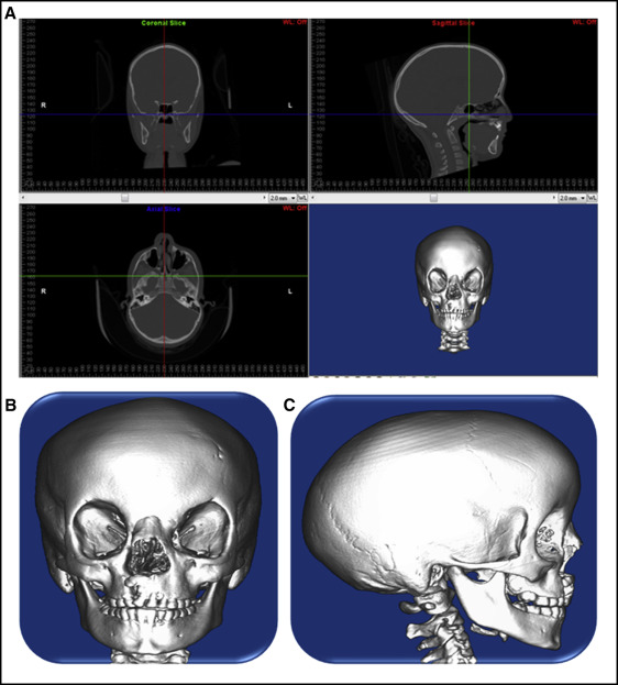
Spiral computed tomography (CT) data originally for medical use were obtained from a 7-year-old girl with amniotic band syndrome and incomplete UCLP (0.300-mm layer; voxel size, 0.463 × 0.463 × 0.300 mm 3 ). The volumetric data from the CT scan was imported using Mimics software (version 13.1; Materialise, Leuven, Belgium) to generate a 3D solid model of the patient’s skull, and the midpalatal suture was incorporated to increase the accuracy in this study ( Figs 1 and 2 ). The hard and soft tissue volumetric data were stored in DICOM format with the relative radiodensity of the CT image represented in Hounsfield units. Threshold segmentation with settings of 238 and 3071 Hounsfield units was used to identify the hard tissues of interest, yielding a 3D mask of the entire skull.
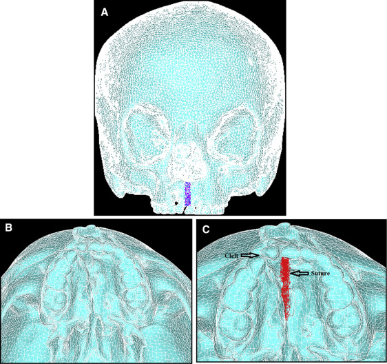
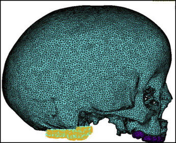
The mask of the model was manually modified to remove the noise to create the complete cleft model needed for this study. Smoothing was performed 3 times on the surface of the mask with the built-in Laplacian function to remove sharp edges. Triangle reduction removed overlapping and redundant triangles that made up the mesh of the FEM. The 3D object was remeshed to reduce the number of triangle elements to a minimum, but enough to still accurately represent the 3D model ( Fig 2 ). The 3D mesh, the FEM of the skull, was imported into a general-purpose finite element analysis software (version 12.0; ANSYS, Canonsburg, Pa).
The material properties assigned to the elements were linear elastic and isotropic ( Table I ). Zero degree of freedom was imposed on the nodes along the foramen magnum ( Fig 3 ).
| Modulus of elasticity, E (GPa) | Poisson coefficient, ν | |
|---|---|---|
| Cortical bone | 13.4 | 0.3 |
| Enamel | 20.2 | 0.3 |
| Suture | 0.08 | 0.49 |
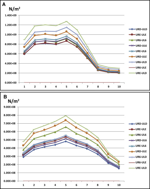
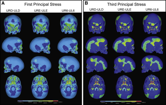
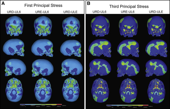
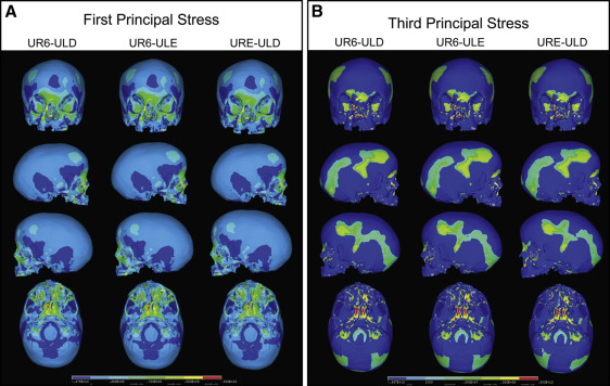
Nine combinations of force application were considered to test all possible combinations of maxillary expansion using the deciduous molars, the permanent molars, or a combination of the molars as anchors ( Table II ). The 9 combinations were divided into 3 groups. Group 1 ( Fig 4 ) had expansion forces applied transversely between the deciduous first and second molars, and the permanent first molars. Group 2 ( Fig 5 ) consisted of 3 simulations with expansion forces applied anteriorly on the cleft side and posteriorly on the normal side. Group 3 ( Fig 6 ) also consisted of 3 simulations with forces applied posteriorly on the cleft side and anteriorly on the normal side.
| Expansion force applied to teeth | Abbreviations |
|---|---|
| Maxillary right deciduous first molar to maxillary left deciduous first molar | URD-ULD |
| Maxillary right deciduous second molar to maxillary left deciduous second molar | URE-ULE |
| Maxillary right permanent first molar to maxillary left permanent first molar | UR6-UL6 |
| Maxillary right deciduous first molar to maxillary left deciduous second molar | URD-ULE |
| Maxillary right deciduous first molar to maxillary left permanent molar | URD-UL6 |
| Maxillary right deciduous second molar to maxillary left deciduous first molar | URE-ULD |
| Maxillary right deciduous second molar to maxillary left permanent first molar | URE-UL6 |
| Maxillary right permanent molar to maxillary left deciduous first molar | UR6-ULD |
| Maxillary right permanent first molar to maxillary left deciduous second molar | UR6-ULE |
Palatal expansion was simulated by applying transverse expansion forces to the maxillary right deciduous first molars (URD) and second molars (URE) or the maxillary permanent first molars (U6) on both sides of the palate. Equal forces were applied between the teeth, and different force combinations were analyzed ( Table II ). Force levels between 700 and 1100 g were applied to achieve 5 mm of anterolateral expansion of the collapsed minor segment to stimulate correction of the anterior crossbite in a patient with UCLP. The transverse forces attempted to stimulate the resultant forces from either a jack-screw type of RPE expansion device placed directly between the teeth across the palate or a 4-banded quad-helix with more activation on the anterior region of the minor segment and minimal expansion of the posterior region. Upon completion of the simulation, first principal, third principal, and von Mises stresses resulting from the virtual RPE were measured.
Results
The FEM generated from the spiral CT data contained 105,357 nodes and 371,605 elements. Element size was varied to keep the number of nodes and elements sufficiently low to maintain an accurate representation of the skull. Smaller elements were used in areas with high variations in the surface contour, such as the nasomaxillary and midpalatal suture regions. Larger elements were used in areas with flatter surfaces, such as the cranium.
When transverse forces were applied at the maxillary permanent molars (UR6-UL6) ( Table II ), the minor and major segments of the maxilla along the cleft site were separated, and the largest transverse displacement was produced at the cusp tips of the maxillary deciduous canines. The expansion of the minor and major segments resulted in a pyramidal opening on the side of the cleft with the base of the pyramid at the floor of the nasal cavity and the apex slightly above the frontonasal suture. For the occlusal aspect, the opening was wider in the anterior than in the posterior between the minor and major segments. The expansion was asymmetric, with greater displacement at the dentoalveolar region on the cleft side than on the normal side. Expansion caused lateral bending of the medial and lateral pterygoid plates of the sphenoid bone, and more displacement was observed at the inferior border of the pterygoid plates than at the superior. Minimal displacement was seen at the supraorbital and forehead regions.
In group 1, transverse expansion forces were applied between the following pairs of teeth: URD-ULD, URE-ULE, and UR6-UL6 ( Table II ). Stress levels on the cleft side were higher in all 3 models than on the normal side, and the highest stress was experienced when forces were applied across UR6-UL6 ( Fig 7 ). The first principal stress distribution plot ( Fig 4 , A ) of all 3 group 1 simulations showed high tensile stresses at the medial wall of the orbit slightly below the junction of the frontomaxillary suture, at the angle of the piriform aperture on the cleft side, and at the inferior rim of the orbit directly above the infraorbital foramen on the normal side. High stress levels were also seen on the inferoposterior area of the zygomatic process of the maxilla and the body of the sphenoid bones.