Introduction
This study provides vital insight in assessing anchorage loss when miniscrews are indirectly loaded.
Methods
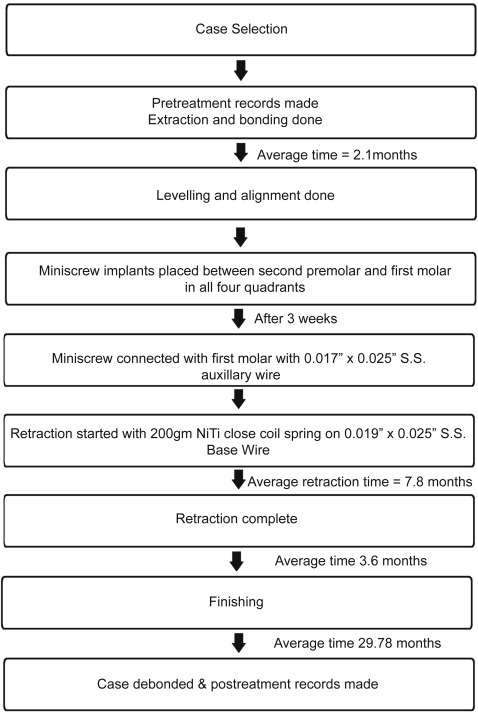
The study sample comprised 18 patients with bimaxillary protrusion (14 girls, 4 boys; mean age, 17.3 ± 4.6 years) selected from a database of 89 patients treated with miniscrews. All subjects who were selected required extraction of all first premolars and maximum anchorage. After initial leveling and aligning, miniscrews were placed between the first molar and the second premolar in all 4 quadrants and loaded by the indirect method at 3 weeks after placement with 200-g nickel-titanium alloy closed-coil springs for en-masse retraction. Mean treatment duration was 29.7 ± 6.8 months. Pretreatment and posttreatment lateral cephalograms were analyzed to measure the amount of anchorage loss, incisor retraction, and the incisors’ angular change in reference to the pterygoid vertical reference line and were evaluated by the structural superimposition method.
Results
The ratio of incisor retraction to molar protraction was 4.2 in the maxilla and 4.7 in the mandible. The first molars showed mean extrusion of 0.20 mm in the maxilla and 0.57 mm in the mandible; these were statistically insignificant. The mean angular change of the first molars was −2.43° in the maxilla and −0.03° in the mandible. The mean anchorage loss in reference to the pterygoid vertical was 1.3 mm in the maxilla and 1.1 mm in the mandible; these were statistically significant. Structural superimpositions showed mean change in molar position of 0.83 mm in the maxilla and 0.87 mm in the mandible, and 5.77 mm in the maxillary incisor and 5.43 mm in the mandibular incisor. These results were compared with the direct anchorage method reported in the literature.
Conclusions
Indirect miniscrew anchorage can be a viable alternative to direct anchorage.
Bimaxillary protrusion has been described as a malocclusion that mars or deforms the human face to a magnitude like no other dentofacial malocclusion and should be treated by extraction of the 4 first premolars and retraction of the anterior segments; otherwise, the patient should be left untreated. The objective for these patients is usually to reduce the lip protrusion and correct the incisor proclination with minimum anchorage loss because they often have Class I molar relationships. Although headgear has traditionally been the gold standard anchorage saver, the intermittent force that it delivers and the prerequisite for patient compliance have led orthodontists to explore alternative anchorage savers, an example of which is the miniscrew.
The miniscrew is a novel, albeit transient, device for anchorage management. Miniscrews have gained immense popularity in eclectic clinical applications because of their miniature size, ease of placement, nondependence on the patient’s compliance, minimal discomfort, and lack of residual surgical defects. The use of miniscrew implants has proven particularly effective, whether the miniscrews are directly loaded (direct anchorage) or used indirectly to stabilize a dental anchorage unit (indirect anchorage).
A recent study documented that in a clinical scenario entailing major orthodontic forces, it is preferred to opt for indirect anchorage to reduce the peri-implant loading of the bone and thereby reduce the peril of miniscrew loosening. Many studies have documented anchorage loss via direct loading ( Table I ). The literature seems deficient regarding anchorage loss exclusively in bimaxillary protrusion patients with indirect loading of miniscrews for anchorage reinforcement. Furthermore, for directly loaded miniscrews, a meta-analysis on orthodontic miniscrews reported failure rates ranging from 0% to 40.8% with an overall failure rate of 13.5%. We were interested to know the failure rate of indirectly loaded miniscrews compared with directly loaded miniscrews in a clinical study since the literature lacks data regarding the failure rate of indirectly loaded miniscrews.
| Author/year | Sample | MSI (n) | Age/sex | Malocclusion | Treatment duration (mo) | Type of anchorage | Mode of anchorage measurement | Anchor loss, mean/SD in MIS group (mm) | Anchor loss, mean/SD in conventional anchorage group (mm) |
|---|---|---|---|---|---|---|---|---|---|
| Thiruvenkatachari et al, 12 2006 | 10 | 18 | 19.6 y (18 to 25 y) (M/F 3/7) | Class I/Class II | Retraction: 4 to 6 | Direct anchorage | Ceph | U6M-0 L6M-0 |
Nonimplant side Max: 1.60/0.35 Mand: 1.70/0.27 |
| Upadhyay et al, 8 2008 | 30: 15 MSI group (G1)/15 conventional group (G2) |
15 | 14 y 5 m to 22 y 3 m (M/F 9/21) | Class I/Class II | Retraction: G1: 9.2, G2: 10.6 | Direct anchorage | Ceph | −0.83/1.4 | Conventional method of anchorage: 2.07/0.68 |
| Lai et al, 9 2008 | 40: Headgear (Group 1): n = 16 Miniscrew (Group 2): n = 15 Miniplate (Group 3): n = 9 |
30 | Group 1 = 21.7 ± 2.5 y (M/F 0/16) Group 2 =25.1 ± 4.7 y (M/F 1/14) Group 3 = 24.1 ± 3 .2 y (M/F 2/7) |
Class I/ Class II | Group 1 = 33.6 ± 7.2 Group 2 = 27.1 ± 4.2 Group 3 = 31.4 ± 4.7 |
Direct anchorage | Model | 1.3/1.0 | 1.4/1.3 with miniplate 2.5/0.9 with headgear |
| Yao et al, 11 2008 | 47: Headgear (Group 1): n = 22 Mini-implants (Group 2): n = 25 |
50 | Group 1 = 22.32 ± 3.92 y (M/F 2/20) Group 2 = 24.72 ± 4.15 y (M/F 2/23) |
Class I/Class II | Group 1 = 29.81± 6.41 Group 2 = 32.29 |
Direct anchorage | Ceph | 0.88/1.24 | Headgear: 2.07/2.31 |
| Kuroda et al, 7 2009 | 22: Implant group (G1): n = 11 Headgear group (G2): n = 11 |
22 | G1=18.5 ± 3.3 y (M/F 0/11) G2 = 21.8 ±7 .9 y (M/F 0/11) |
Class II | NM | Direct anchorage | Ceph | Max: 0.7/0.64 Mand:1.4/1.65 |
Headgear Max:3.0/0.76 Mand:3.3/2.03 |
| Lee and Kim, 13 2011 | 40: Conventional (Group 1): n = 20 Mini-implants (Group 2): n = 20 |
40 | Group 1 = 22.16 ± 3.11 y (M/F 0/20) Group 2 = 24.64 ± 7.85 y (M/F 0/20) |
Class I | Group 1 = 28 ± 8.37 Group 2 = 24.95 ± 4.55 |
Direct anchorage | Ceph | U6M: 0.24/1.62 U6A: 0.27/1.15 |
Headgear U6M: 2.19/1.40 U6A: 2.42/1.68 |
| Davoody et al, 10 2012 | 28: Differential moment (G1): n =15 Miniscrew (G2): n = 13 |
26 | G1 = 17.9 ± 8.96 y (M/F 5/10) G2 =17.4 ± 8.85 y (M/F 7/6) |
Class I/Class II | NM | Direct anchorage | Ceph | −0.69/0.97 | Canine retraction followed by incisor: 2.55/1.8 |
Therefore, this study was done to determine whether we could achieve results commensurate with our idealistic goals when indirect anchorage was used with miniscrews in Class I patients with bimaxillary protrusion requiring maximum anchorage.
Material and methods
This retrospective study was conducted on a sample of 18 patients with bimaxillary protrusion who were selected from a database of 89 patients treated with miniscrew-supported anchorage (mean age, 17.3 ± 4.6 years; range, 13-32 years; 14 girls, 4 boys) ( Fig 1 ). Ethical clearance was obtained from the ethics committee of the All India Institute of Medical Sciences in New Delhi. The inclusion criteria consisted of Angle Class I malocclusion patients with bimaxillary protrusion requiring group A space closure with minimal crowding (≤4 mm) and satisfactory periodontal health before orthodontic treatment, a skeletal Class I pattern with an ANB angle less than or equal to 4°, and an interincisal angle less than 124°. The exclusion criteria consisted of patients with malocclusion requiring groups B and C space closure with moderate to maximum crowding, poor oral hygiene, history of drug intake, systemic disease, hormonal imbalance, and previous orthodontic treatment. The mean changes in skeletal parameters of our sample are shown in Table II .
| Parameter | Pretreatment mean/SD | Posttreatment mean/SD | Mean change/SD |
|---|---|---|---|
| FMA (°) | 24.7/6.1 | 25.2/6.1 | 0.5/0.64 |
| SN-GoGn (°) | 28.9/6.5 | 29.8/6.8 | 0.8/0.83 |
| ANB (°) | 3.0/0.9 | 3.4/1.1 | 0.4/0.64 |
| Interincisal angle (°) | 103/6.9 | 121.2/8.1 | 17.70/9.10 |
| U1-SN (°) | 116/18.2 | 106.1/16.9 | −9.3/4.7 |
| IMPA (°) | 109.3/7.4 | 100.4/11 | −8.8/6.3 |
| Jarabak ratio (%) | 62.1/3.2 | 62.5/3.7 | 0.4/1.3 |
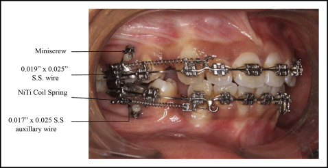
After pretreatment records were taken, each patient was bonded with Roth prescription (0.022 × 0.028 in; Rocky Mountain Orthodontics, Denver, Colo). The sequence of wires included 0.016-in stainless steel followed by 0.018-in stainless steel, 0.017 × 0.025-in stainless steel, and 0.019 × 0.025-in stainless steel. Standard ligation was used. After the leveling and aligning phase of treatment, miniscrews (length, 8 mm; diameter, 1.5 mm; bracket head type, Absoanchor; Dentos, Daegu, South Korea) were placed in the buccal interradicular bone in the attached gingiva between the second premolar and the first molar under local anesthesia at an angle of 60° to the long axis of the teeth. Miniscrews were connected to the first molars passively using a 0.017 × 0.025-in stainless steel wire auxiliary (AIIMS universal connector; AIIMS, New Delhi, India), thereby providing indirect anchorage. Indirect loading of the miniscrews and thereby en-masse retraction was started 3 weeks after miniscrew implantation with a 9.0-mm nickel-titanium alloy closed-coil spring (200-g force) ligated to the soldered hook between the lateral incisor and the canine on 0.019 × 0.025-in stainless steel wire in each arch ( Fig 2 ). The posttreatment records were made within 2 weeks after debonding of all patients.
Lateral cephalometric radiographs acquired before and after treatment were traced manually by an investigator (N.M.).
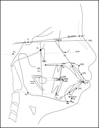
The following linear measurements were made in the sagittal plane. A horizontal reference line was drawn 7° to the sella-nasion plane. A perpendicular line to horizontal reference line was drawn passing through pterygoid and was called the vertical reference line (VRL). All linear measurements in the sagittal plane were made from the VRL. These measurements included distance of maxillary and mandibular first molar mesial contact point (U6M and L6M) and apex (U6A and L6A) from the VRL. Also, the maxillary and mandibular incisor edges (U1E and L1E) and apices (U1A and L1A) were measured from the VRL.
The following linear measurements were made in the vertical plane. The palatal plane (ANS-PNS) was used as the reference plane for the maxillary teeth, and the mandibular plane (Go-Me) was used as the reference plane for the mandibular teeth. A perpendicular line passing through the mesial cusp tips of the maxillary and mandibular first molars was extended until it intersected the palatal and mandibular planes, respectively. This line was measured, and it indicated the amount of movement in the vertical plane of the first molar. A line passing through the maxillary and mandibular incisal edges was extended until it intersected the palatal and mandibular planes, respectively.
The following angular measurements were made. The internal angle between the palatal plane and the long axis of the maxillary incisor and first molar mesial root long axis was measured. Similarly, the internal angle between the mandibular plane and the long axis of the mandibular incisor and first molar mesial root long axis was measured.
The landmarks and reference planes used for this study are shown in Figure 3 .
The maxillary and mandibular superimposition was performed to measure the dental movement accurately by minimizing the influence of growth on the measurements. For this purpose, Bjork’s structural superimposition method modified by Johnston was used.
In the maxilla, the zygomatic process of the maxilla and the bony anatomic details superior to the incisors were used for best-fit registration. Orientation was further assisted via the superior and inferior surfaces of the posterior hard palate.
In the mandible, regional superimposition was done with greater validity via the mandibular canal, tooth germs (before root formation), and bony architecture in the labial aspect of the symphysis. If these bony details were absent, blurred, or distorted, then the mandibular plane was used as an alternative orientation line.
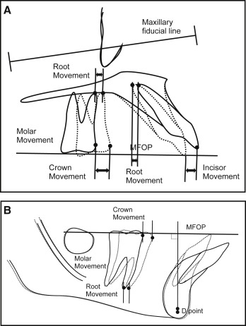
The structural superimposition method by Johnston uses the best-fit line passing through the occlusal overlap in the region of the first molars, premolars, and canines known as the functional occlusal plane (FOP). To analyze a 2-film series, the maxillae were superimposed, and the 2 FOPs were averaged to yield a mean FOP (MFOP) that was then transferred to both tracings. From the vantage point of a superimposition in either the maxilla or the mandible, tooth movement was then measured parallel to the MFOP. Molar crown movement was measured at the mesial contact point, and root movement was measured at the mesiobuccal root apex ( Fig 4 ).