Introduction
The center of resistance is considered the most important reference point for tooth movement. It is often stated that forces through this point will result in tooth translation. The purpose of this article is to report the results of numeric experiments testing the hypothesis that centers of resistance do not exist in space as 3-dimensional points, primarily because of the geometric asymmetry of the periodontal ligament. As an alternative theory, we propose that, for an arbitrary tooth, translation references can be determined by 2-dimensional projection intersections of 3-dimensional axes of resistance.
Methods
Finite element analyses were conducted on a maxillary first molar model to determine the position of the axes of rotation generated by 3-dimensional couples. Translation tests were performed to compare tooth movement by using different combinations of axes of resistance as references.
Results
The couple-generated axes of rotation did not intersect in 3 dimensions; therefore, they do not determine a 3-dimensional center of resistance. Translation was obtained by using projection intersections of the 2 axes of resistance perpendicular to the force direction.
Conclusions
Three-dimensional axes of resistance, or their 2-dimensional projection intersections, should be used to plan movement of an arbitrary tooth. Clinical approximations to a small 3-dimensional “center of resistance volume” might be adequate in nearly symmetric periodontal ligament cases.
The concept of the center of resistance of a tooth is analogous to the concept of the center of mass of a free body. The center of resistance, initially idealized in 2 dimensions, can be determined by the iterative trial application of a force until it results in translation, or by the application of a couple. In 2 dimensions, the center of resistance coincides with the center of rotation when a couple is applied because the resultant force is zero, and the center of resistance does not translate in absence of a resultant force. Tooth movement is typically described taking into account the position of the center of resistance or the moment-to-force ratio curves that are available in the literature.
The assumptions involved in the determination of the center of resistance have not been formalized. When determining it, there are problems related to material properties, 2-dimensional (2D) vs 3-dimensional (3D) clinical validity, and inaccuracies related to the methods of determination. As orthodontics shifts into 3D technology and tooth movement planning, it is crucial to revisit this concept to develop a 3D scientific theory of tooth movement.
Here, we hypothesize that the center of resistance does not exist as a point in 3D space primarily because of general periodontal ligament (PDL) and tooth asymmetry. Thus, its definition should, in this case, be limited to 2D projections and a specific loading direction. We will perform numeric experiments on a maxillary first molar to test these hypotheses. After disproving that a general theory of the 3D center of resistance is true with a counter-example, we will provide and test an alternative 3D concept, the axes of resistance. Then, we will demonstrate how to link the 2D projected centers of resistance and 3D axes of resistance concepts.
The first problem in the center of resistance concept is the choice of assumption of rigidity of the dentoalveolar units. Analytic studies incorporated this as a necessary simplification to mathematically calculate root centroids, assuming that they are close to the centers of resistance. In contrast, contemporary studies typically model nonrigid mineral units to determine centers of resistance. The uncertainty about these assumptions is most likely because the scientific determination and clinical purpose of the center of resistance are somewhat different problems. If PDL stresses initiate orthodontic mechanotransduction, and bone and tooth bending will be mostly reversed after load application is removed, bone and tooth nonrigid displacements are likely irrelevant to the final tooth movements. On the other hand, the scientific determination of the center of resistance is limited to instantaneous tooth displacement before bone modeling takes place. The clinical extension of the use of the concepts of resistance is the planning of long-term tooth movement. This extension requires the often-overlooked assumption that the catabolic bone response is directly proportional to the initial deformation pattern of the PDL. Bone modeling relationships with PDL stresses and strains have only recently started to become clear with translatable biomechanical models. It has been recently observed that the critical entity in instantaneous tooth displacement is the PDL, and bone and teeth could be reasonably assumed to be rigid to define PDL stresses for tooth movement.
The second major issue in the definition of center of resistance is related to its technical determination. In autopsy specimens, a major weakness was that the tooth displacement gauge itself could load the tooth, therefore causing errors. This difficulty was overcome by mathematical adjustments, with laser holographic interferometry or magnetic sensors. The most commonly used contemporary method to evaluate tooth displacement is numeric, using finite element analysis, which offers much more flexibility on modeling conditions. Nonlinear PDL behavior is characterized approximately by a nonlinear (bilinear) stress-strain curve: the 2 lines separated by a strain threshold. Therefore, linear modeling of the PDL for finite element analysis could be considered fairly accurate if loads are kept sufficiently low to maintain PDL strains in the first section of the curve. However, for a general load magnitude model, the PDL must be modeled nonlinearly because load magnitude can affect the data. Studies on PDL properties have most recently explored anisotropy, hyperelasticity, and inclusion of PDL fibers (material properties and orientation are yet mostly undefined experimentally). Development of these models is important; however, unlike many compound (matrix and fibers modeled together as a single entity) linear and nonlinear models, there are limited experimental data on tooth displacement to match the mathematical level of sophistication of such complex models.
The final major issue related to the concept of center of resistance is its actual existence as a point in 3D space in a nonidealized (asymmetric) tooth and PDL. In 3 dimensions, a couple causes rotation of a body about an axis of rotation. Hence, in the general case, application of a couple in 3 dimensions is not sufficient to determine a 3D center of resistance. The idea that the center of resistance exists as a point in 3 dimensions comes from previous studies that idealized a 3D tooth with symmetric roots, calculating the centroid of the root modeled as a paraboloid of revolution. This assumption is a simplification because, in reality, PDL deformations are major determinants of the pattern of tooth displacement. Moreover, the roots and the surrounding PDL of an arbitrary tooth have asymmetric surfaces that can result in asymmetric deformation patterns.
Nagerl et al, in a pioneering experiment, concluded that “the centers of resistance depended on the direction of load application.” This statement was repeated in more recent studies, with 3D models for several types of teeth and modeling approaches. However, these studies did not address the main theoretical difficulty: in 3 dimensions, the concept of a center of resistance as a point is not a general realistic case. There is no working theory to connect 2D models of centers of resistance to 3D axes of resistance. The concept of axes of resistance of a tooth was introduced in a comprehensive numeric study of the mechanical environment of tooth movement. In this same study, it was noted that the axes of rotation generated by orthogonal moments in 3 dimensions (axes of resistance) did not intersect in a 3D center of resistance point.
Material and methods
The maxillary left buccal segment of a dry skull (from first premolar to second molar) was scanned and reconstructed with a cone-beam computed tomography iCAT system (Imaging Sciences International, Hatfield, Pa). The voxel resolution of the scan was 0.125 mm.
The reconstructed voxel data were loaded into ScanIP/FE software (version 4.3; Simpleware, Exeter, United Kingdom) for image segmentation. Gray scale thresholding was used as an initial partition, differentiating between the maxillary bone and each posterior tooth. The floodfill tool (an implementation of the region growing algorithm) was used to isolate each tooth and bone based on pixel connectivity; this allowed for a separate mask (color coding) of each entity. To create the PDL, each tooth’s mask was duplicated. Then, the dilation tool was used on this new “accessory” mask to expand about 2 voxels (250 μm) away from the tooth, and the resulting pixels were subtracted from the total mineral mask. This method produced fairly accurate and nonuniform PDL thicknesses, varying from approximately 0.15 to 0.5 mm, depending on location, with adapted connections between bone, tooth, and PDL.
The 3D mask surfaces were smoothed with a topology-preserving algorithm, eliminating minor voxel irregularities while preserving the surface morphology. By using a direct mask-to-mesh technique, a quadratic tetrahedrone mesh was produced. The meshing algorithm was optimally adjusted to provide a minimum of 2 tetrahedron elements in the PDL space between bone and tooth, optimizing nodal displacement accuracy in this material. The resulting mesh had 618,428 elements, with less than 0.001% ill-shaped tetrahedrons. The mesh with its material properties was imported into the APDL software (ANSYS, Canonsburg, Pa) for finite element analyses. The preconditioned conjugate gradient iterative solver at the 10 −8 level of accuracy was used.
The maxillary first molar dentoalveolar complex model was isolated for this analysis because of its intricate morphology and had up to about 600,000 elements after postresult refinements. Rigid and nonrigid mineral properties were modeled. In the nonrigid model, the boundary conditions were determined by constraining the bone at its apical and anteroposterior limit surfaces. The finite element model characteristics and development process are described in Figures 1 and 2 . The tooth-size measurements approximate an average maxillary first molar and are shown by the black arrows in Figure 3 .
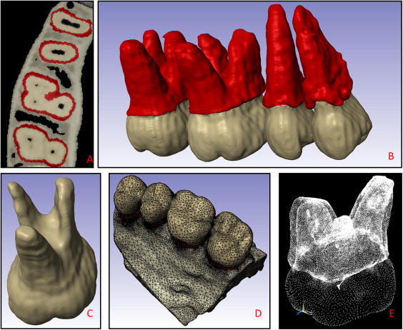
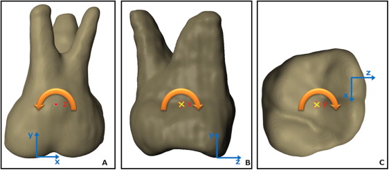
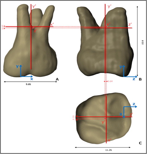
Table I summarizes all material properties used in this study. Material properties of the bone were modeled as heterogeneous. The cortical bone element material properties ranged from approximately 10 to 20 GPa, and trabecular bone properties from 10 GPa to 0.05 MPa. These properties were assigned on an individual element basis; ie, Young’s modulus of each element was approximated as proportional to its gray scale according to a mathematical relationship determined previously by Cory et al. The PDL material properties were assigned based on the experimental tooth displacement data of Poppe et al.
| Structure | Nonrigid bone and tooth model | Rigid bone and tooth model | ||
|---|---|---|---|---|
| Young’s modulus | Poisson’s ratio | Young’s modulus | Poisson’s ratio | |
| Enamel | 80000 | 0.3 | 800000 | 0.3 |
| Dentin | 20000 | 0.3 | 800000 | 0.3 |
| Bone | 0.05-20000 | 0.325 | Constrained | 0.325 |
| PDL ∗ (<7.5% strain) | 0.05 | 0.3 | 0.05 | 0.3 |
∗ The PDL was modeled as linear because the experiments were performed with loads that lead to PDL principal strains <7.5%: ie, distalization and expansion forces up to 1 N and intrusive forces up to 0.4 N.
For this study, we restricted our load ranges to produce strains within the lower tail of the PDL’s nonlinear curve, allowing for assuming a linear isotropic behavior of 0.05 MPa. We chose to limit our study to small PDL loads because the PDL stiffening that occurs in higher loads could, by itself, affect the results of the axes of resistance. Therefore, it would be difficult to mathematically separate the effect of geometric asymmetry from the effect of localized PDL stiffening on the location of the axes of resistance. These modeling decisions warranted a more confident result on the specific effect of geometric asymmetries on the location of the axes of resistance, which are the focus of our hypothesis.
The number, displacement, and coordinates of the node that defines the axis of rotation were recorded with an initial couple load of 3 Nmm. The moment vector determined the direction of each axis of resistance. Peak PDL principal strains were under 7.5% in all directions with this load, thus justifying PDL linear properties at E = 0.05 MPa. Cross-product matrix calculations were performed by inputting nodal coordinates and the final moment value, to output the necessary nodal forces to obtain a moment vector parallel to each coordinate system axis to the tooth ( Figs 1, E , and 2 ). A moment of a couple parallel to the x direction, for example, generates a rotation axis that generates nodal displacement in the y and z directions. This couple-derived axis of rotation (x′) was then tested as one of the 3 axes of resistance. The same procedure was performed for the other axes. We further approximated the coordinates of the node that defined each axis by iterative refinement of the mesh around the node with the lowest displacements in the plane of movement, until the position varied within ±0.05 mm. The displacement error generated by this error in the position of the axes was then calculated by finding the displacements caused by moments generated by translation forces as far as ±0.05 mm from the axes. This is possible by application of the superposition principle, a convenience of the linear model: the displacement in all directions of the translation tests, and the “error displacement” caused by the residual moment error can be summed to estimate a total displacement error range. The error was estimated in worst-case scenarios when maximum and minimum displacement errors were added or subtracted from the translation test displacements near the root apex and the crown. Hence, the smaller the differences between total displacements, the closer the tooth is to translation. This method to determine the axes of rotation, which must be associated with an error analysis, was necessary because analytic calculations of the axes of rotation yield different results depending on which nodes are chosen in the case of a nonrigid model.
We produced a rigid tooth and bone model to estimate the often-neglected error caused by bone and tooth bending (and their associated asymmetric bending behavior in different directions) on the determination of the axes of resistance. Bone rigidity was modeled by simply assigning zero displacements in all directions as boundary conditions for all nodes. To establish the ideal degree of tooth rigidity within the limits of our model’s mesh density, first, a couple was applied in each of the 3 spatial directions. Analyses were then run iteratively at progressively larger tooth elastic moduli (this time, homogeneous for enamel and dentin) until the node number of the lowest displacement node of the tooth no longer changed for our load of interest (ie, the effect of tooth bending no longer affected the result). It was sufficient to increase the elastic modulus of the tooth to 800 GPa to simulate rigid behavior for our established axes of resistance determination error.
After the axes of resistance were obtained in the rigid and nonrigid models, further analyses were limited to the rigid bone and tooth model only. To ascertain the correct combination of axes to obtain translation, we applied 0.4 N (+y = intrusion) and 1.0 N (+z = expansion; +x = distalization) forces at 2 planar centers of resistance defined from the planar orthogonal projections of the axes of rotation determined with the couples. This procedure was repeated according to the 2 possible center of resistance definitions for each plane (xz, yz, xy), for a total of 3 × 2 loading scenarios: (1) along each hypothetical axis of resistance point projection (eg, the y′ point in the xz plane), and (2) at the intersection of the other axes of resistance (eg, the x′z′ point on the xz plane), resulting in a hypothetical 2D projected center of resistance.
The forces generated maximum principal strains in the PDL of less than 7.5% and therefore are compatible with our experimentally validated linear modeling approach.
Stay updated, free dental videos. Join our Telegram channel
VIDEdental - Online dental courses


